InduTech instruments PMD2450-2 Moisture Measurement System User Manual User Guide
InduTech instruments GmbH Moisture Measurement System User Guide
UserManual.wiki
>
InduTech instruments
>
PMD2450 2 User Manual
User Guide
Navigation menu
Upload a User Manual
Namespaces
Wiki Guide
HTML
PDF
Info
Views
User Manual
Discussion / Help
Navigation
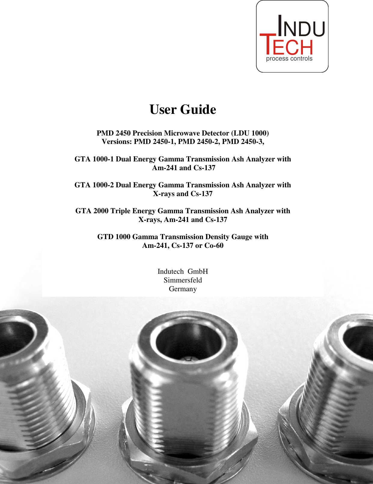
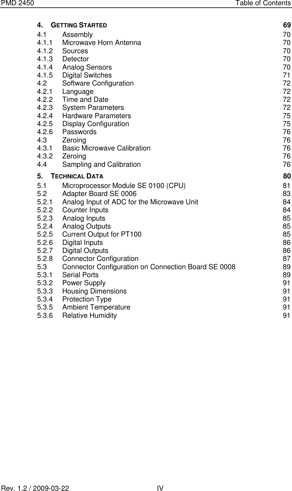
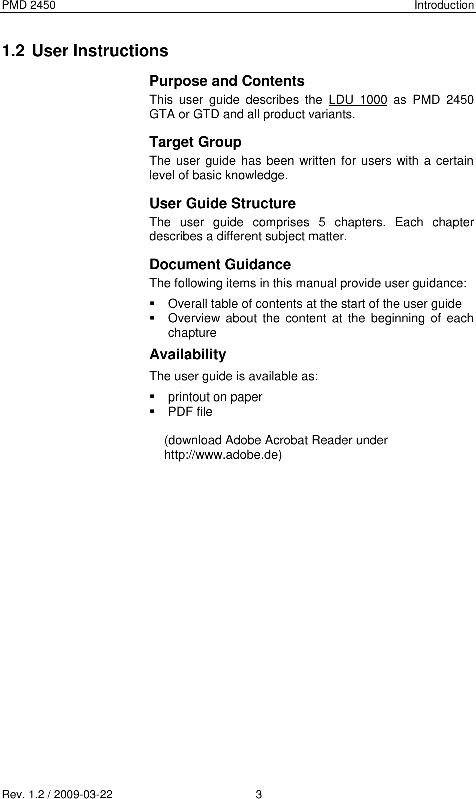

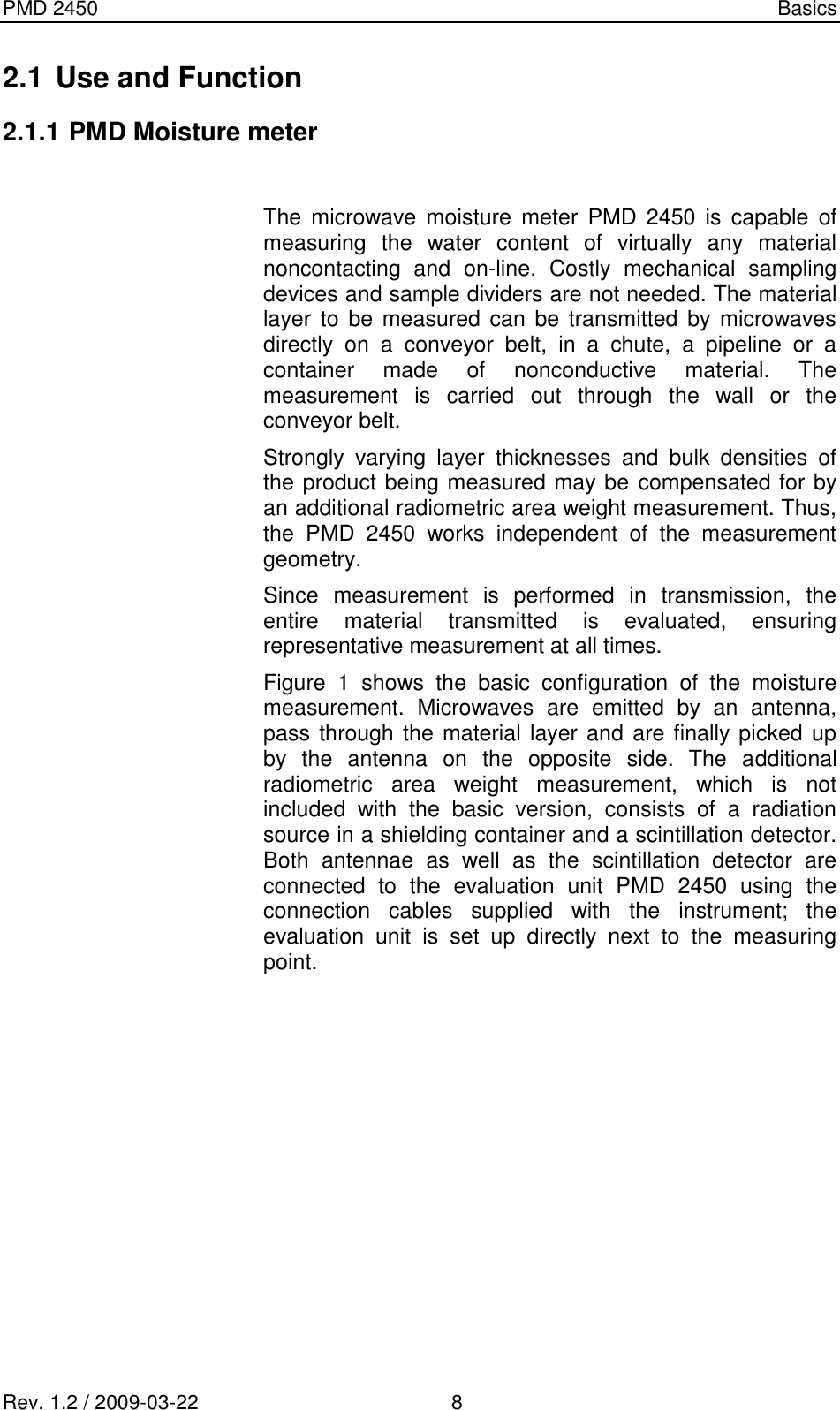
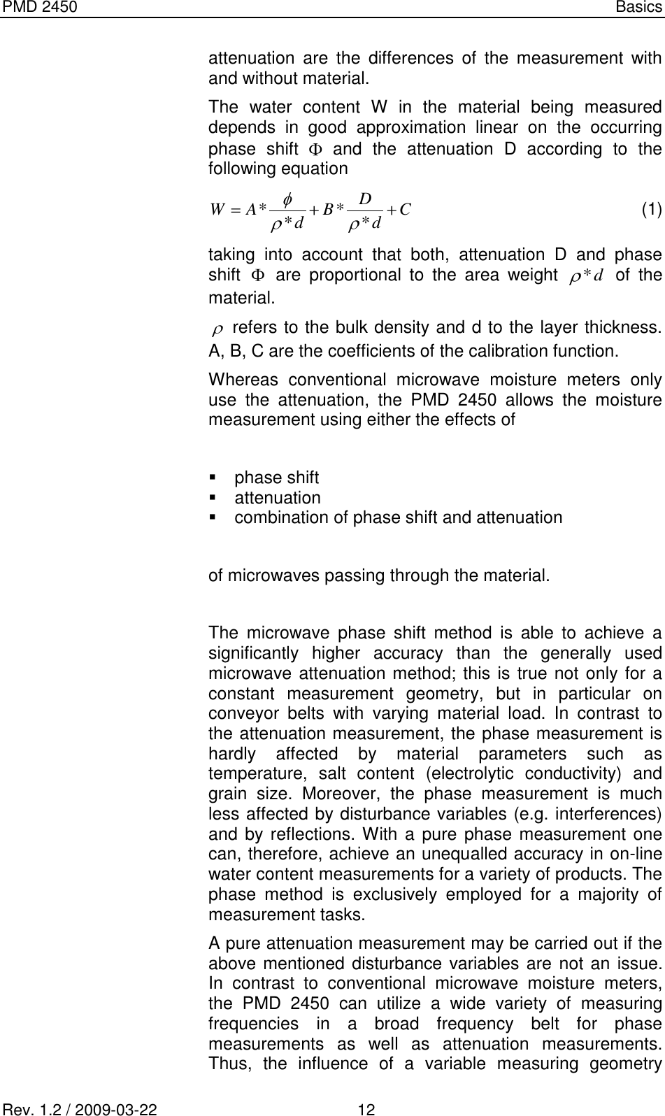
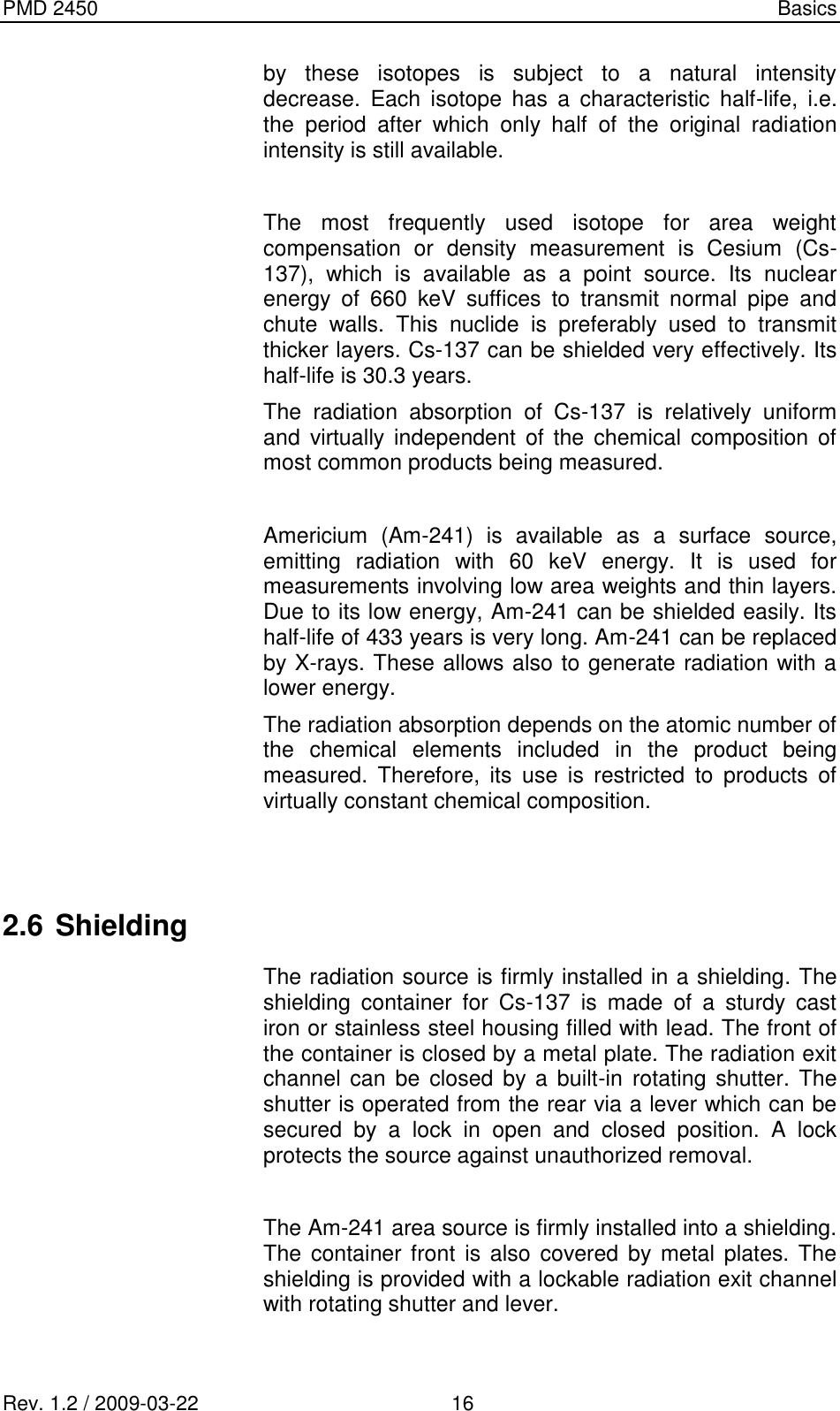
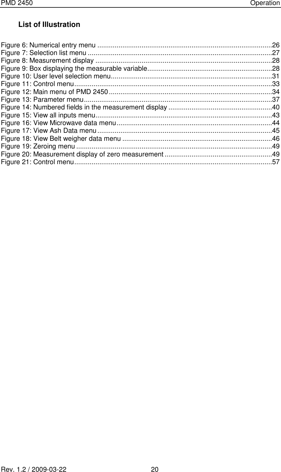
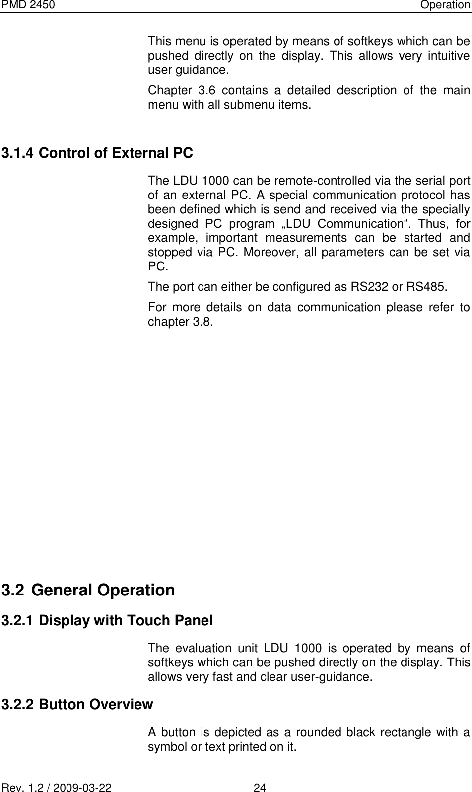
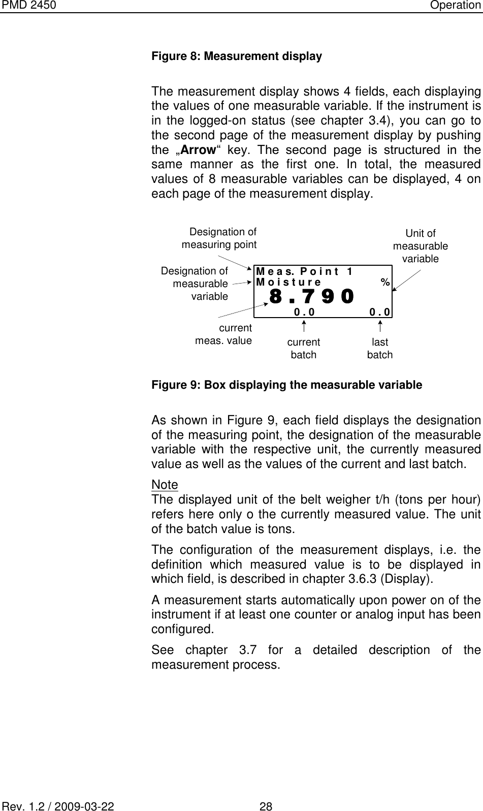
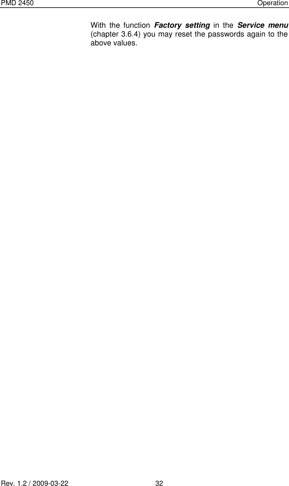
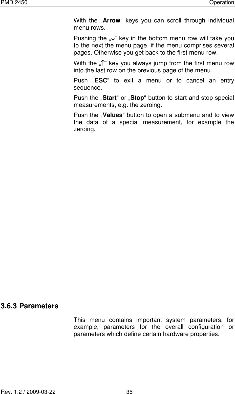
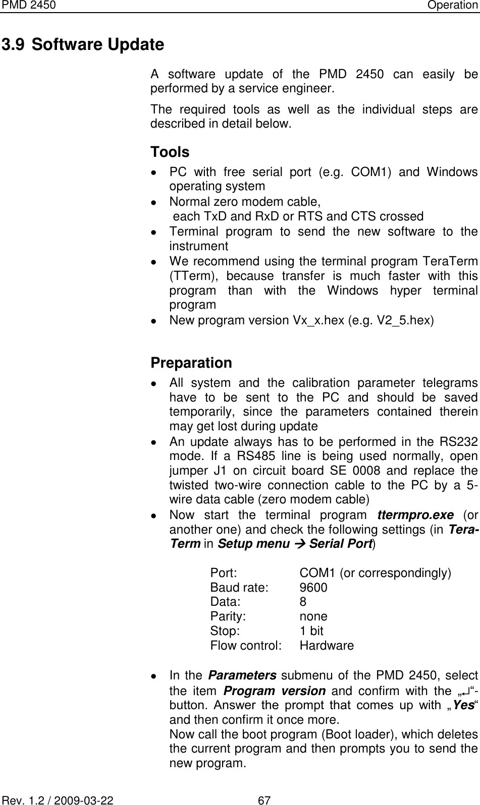
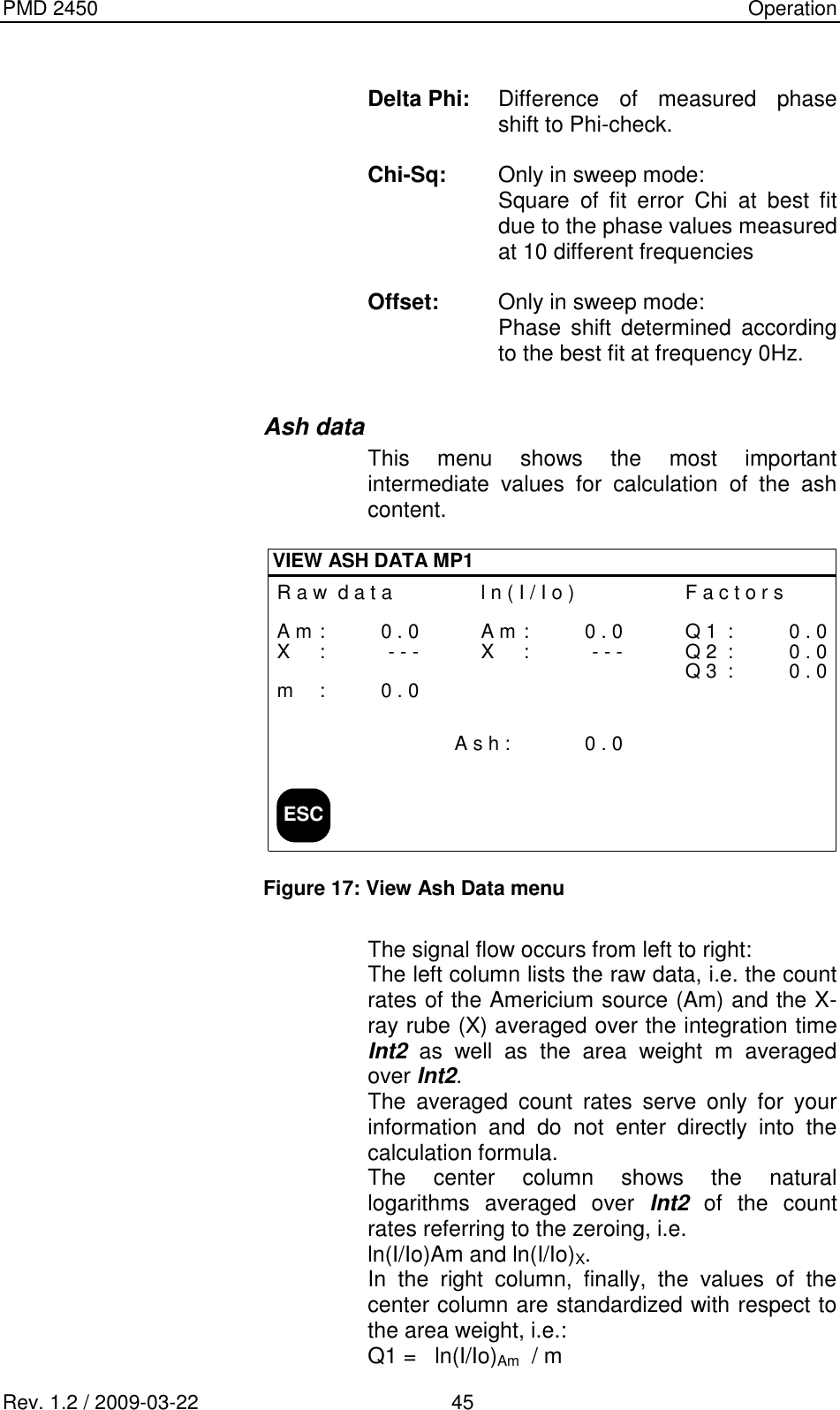
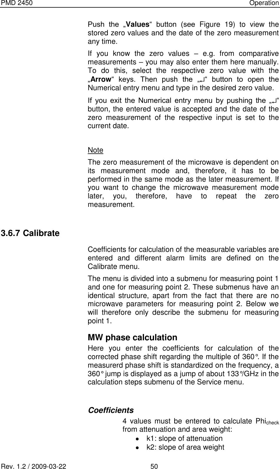
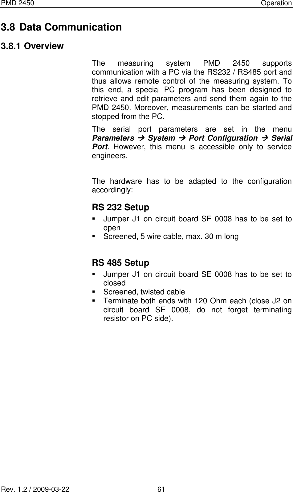
![PMD 2450 Operation Rev. 1.2 / 2009-03-22 43 View All Inputs In this menu all values of the hardware inputs averaged over the integration time Int2 are displayed. If a measurement is running, these values are updated each second. ESCVIEW ALL INPUTSM i c r o w a v eA t t : 0 . 0 1 6Phi : - 1 . 7 1 3A n a l o g I n1 : 0.02 : 0.0C o u n t e r s1 : 0 . 02 : 0 . 03 : 0 . 04 : 0 . 05 : 0 . 06 : 0 . 0D i g I n1 : 12 : 13 : 14 : 15 : 16 : 17: 18: 1 Figure 15: View all inputs menu Calculation Steps Intermediate results for calculation of the measurable variables are displayed in this menu. The results for each measuring point are display in a separate submenu. Both submenus basically have the same structure. Below, only the submenu of measuring point 1 will be discussed. The software supports all applications. However, if not all applications have been implemented, the respective submenus are missing. Tacho Displays the current belt speed [m/s] calculated according to Tacho constant * count rate. If no tachometer is available, the respective row shows the info „Tacho not configured“. Area weight Current area weight determined either radiometrically or by an analog sensor.](https://usermanual.wiki/InduTech-instruments/PMD2450-2/User-Guide-1565946-Page-49.png)
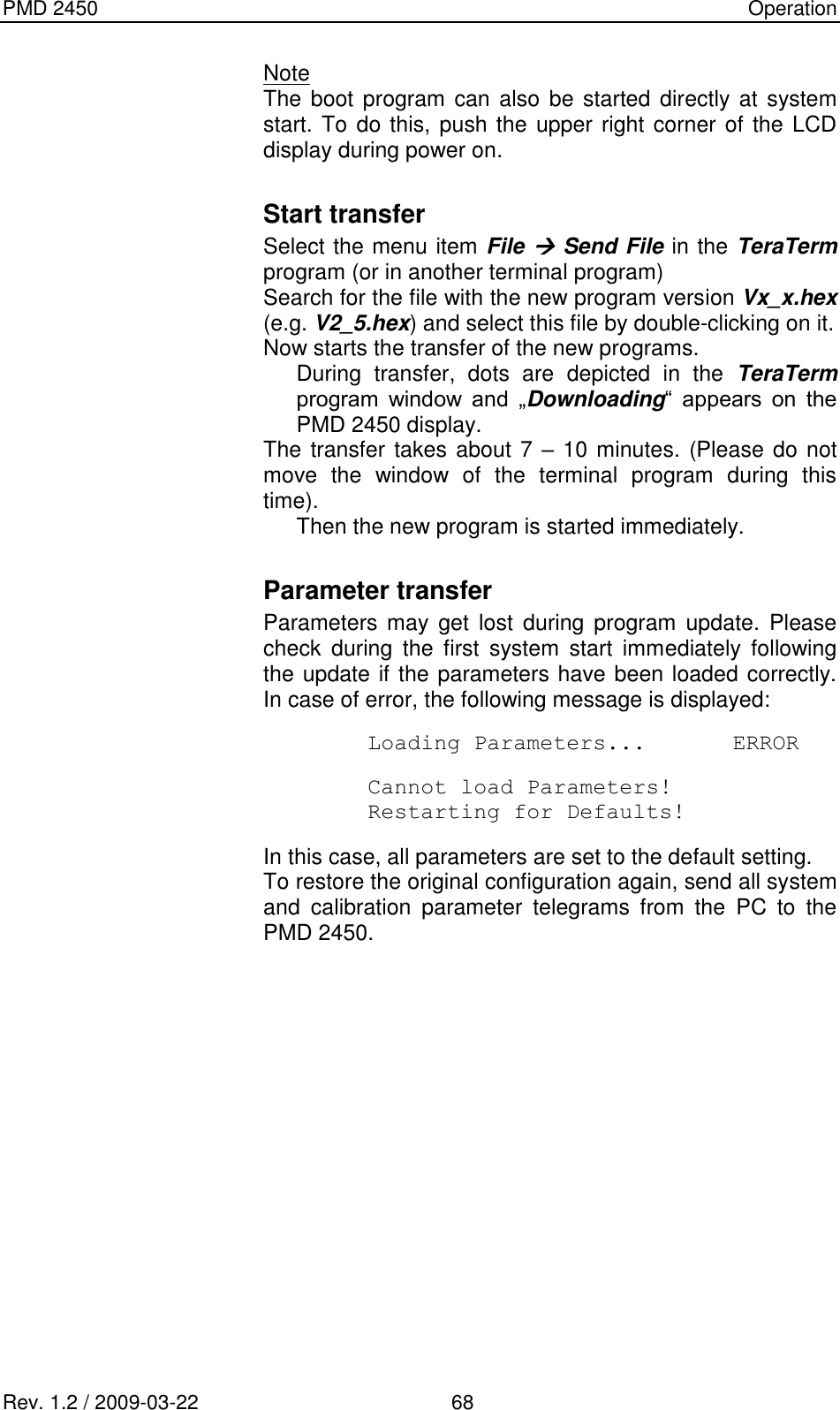
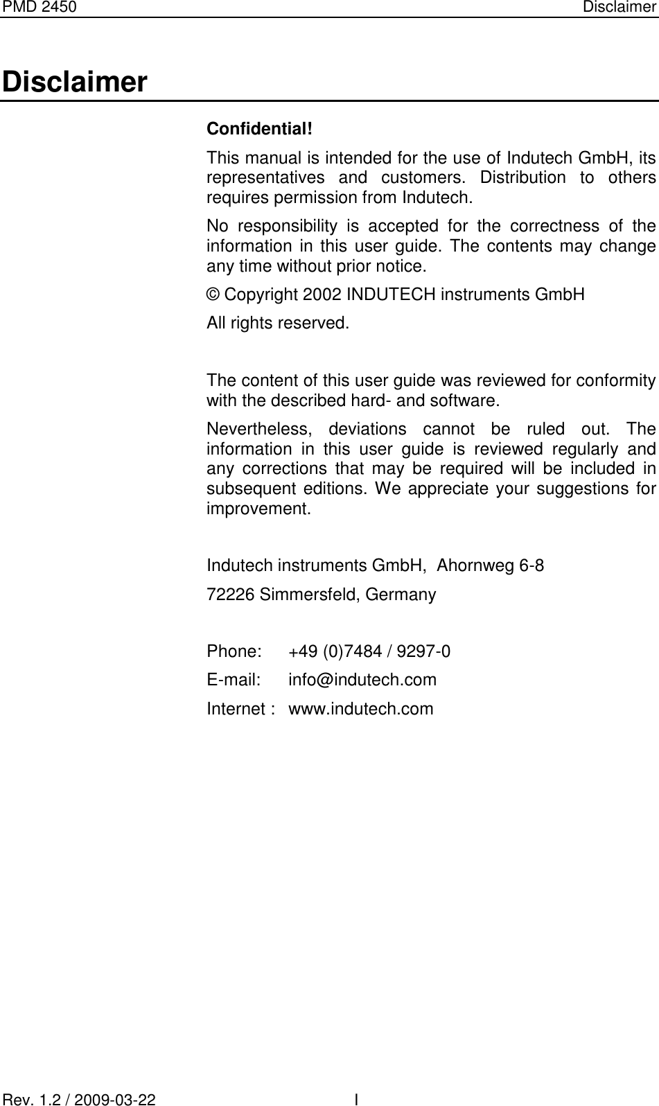
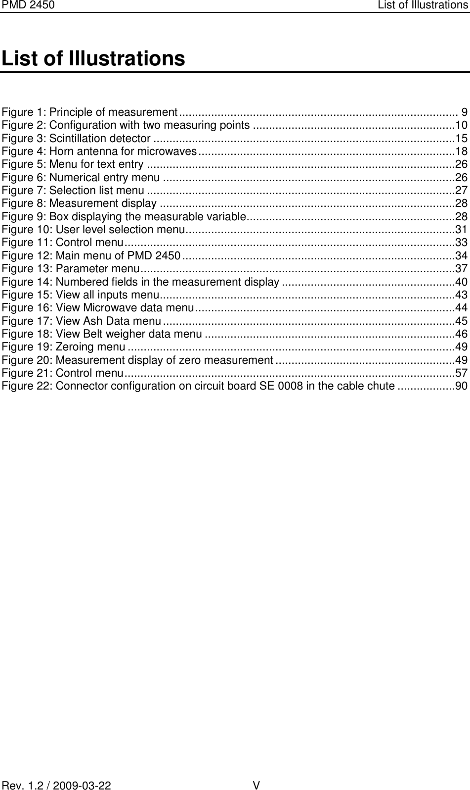
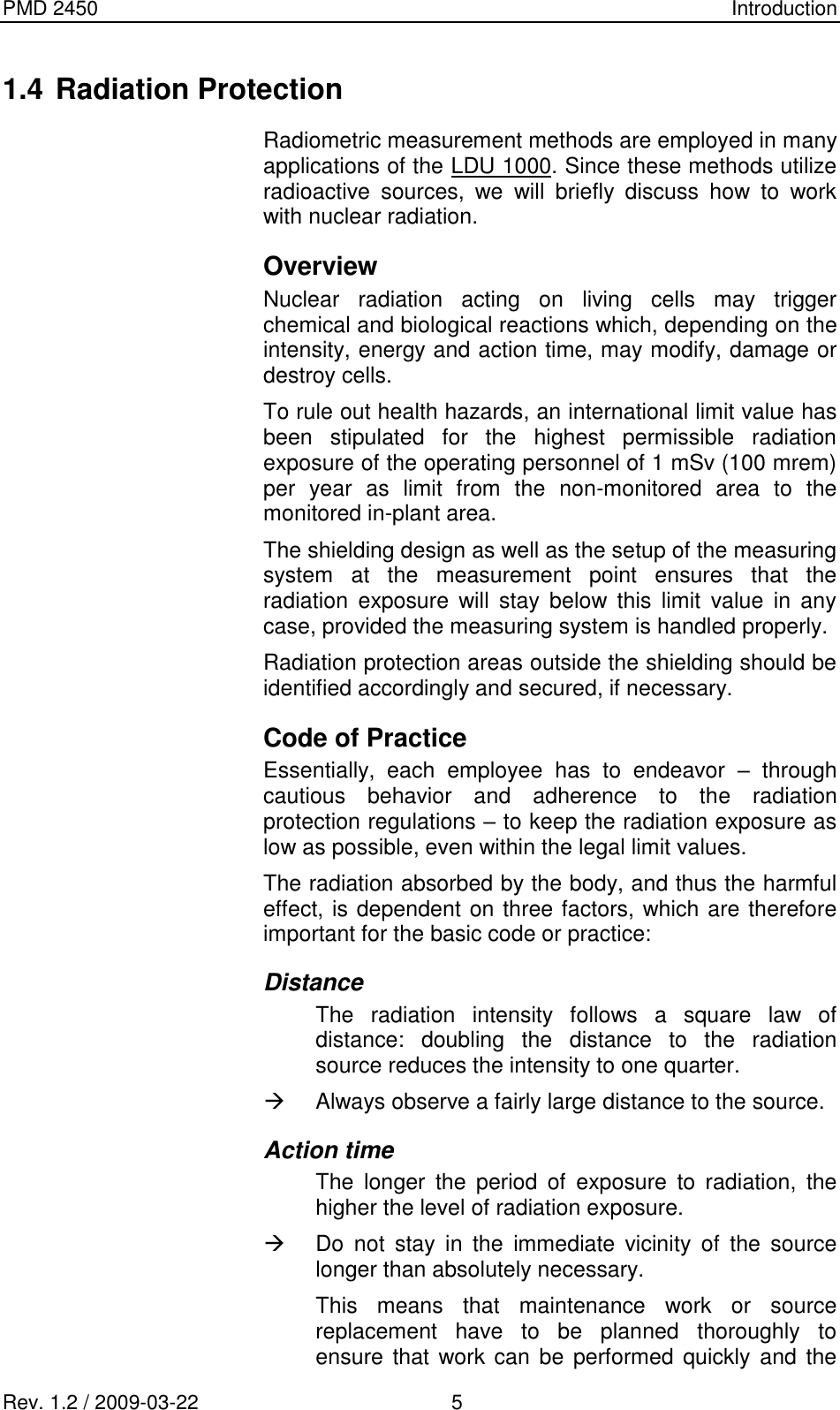
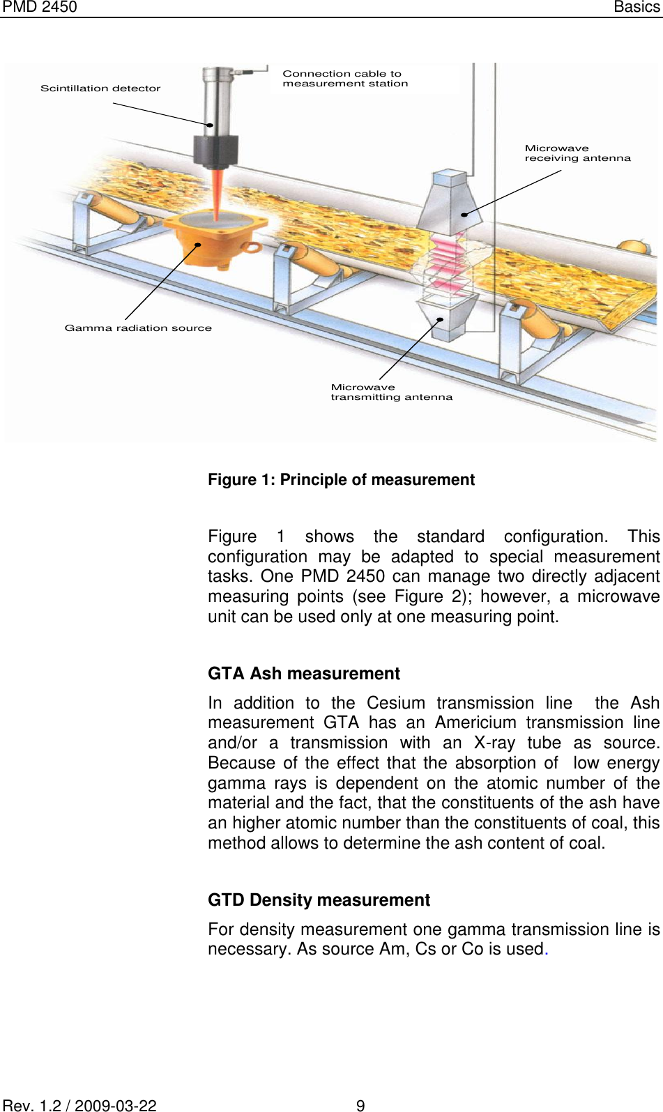
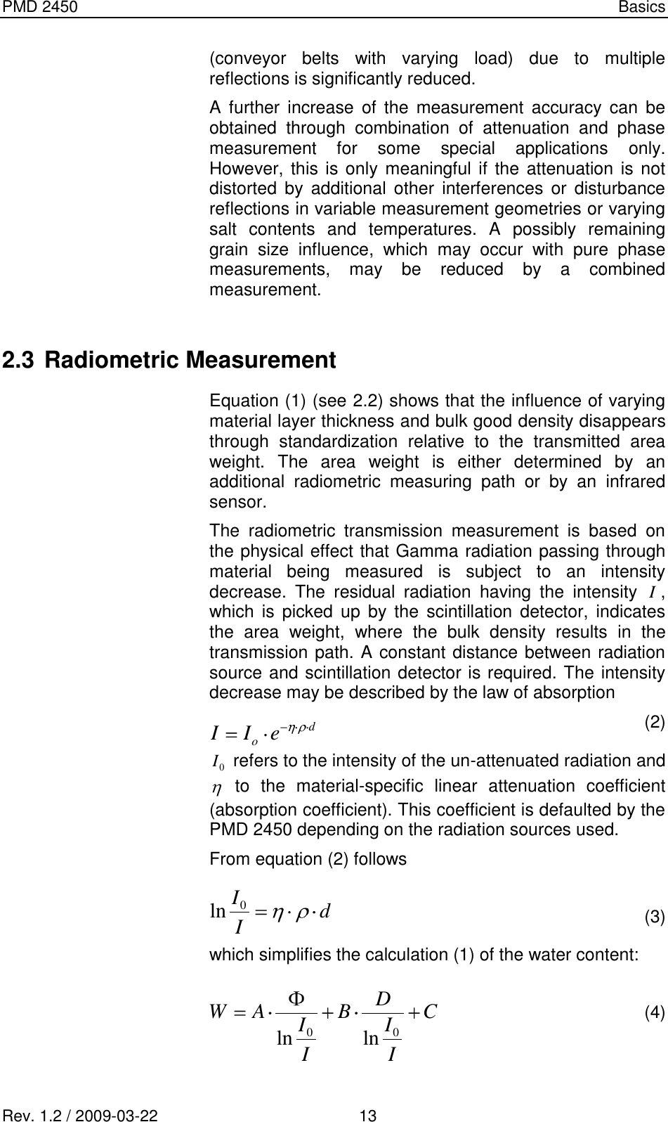
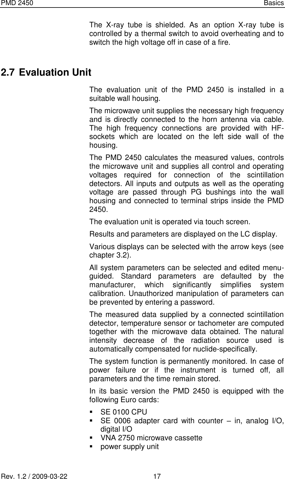
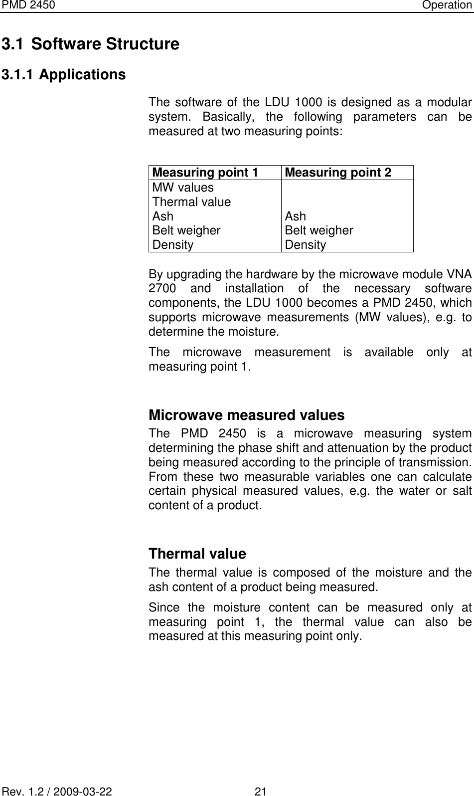
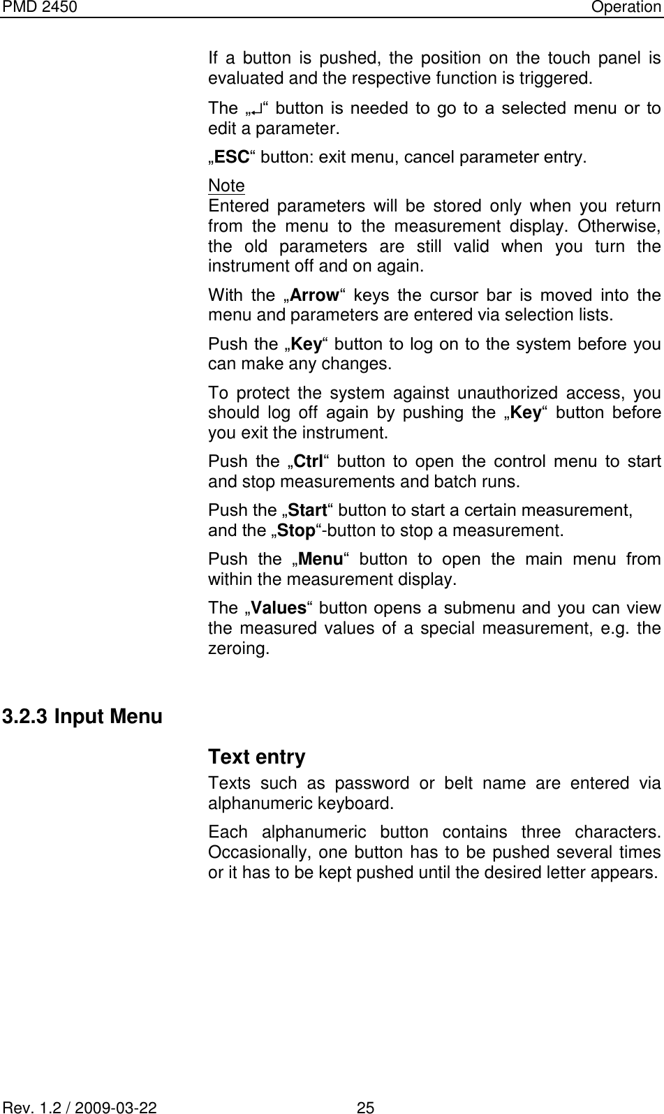
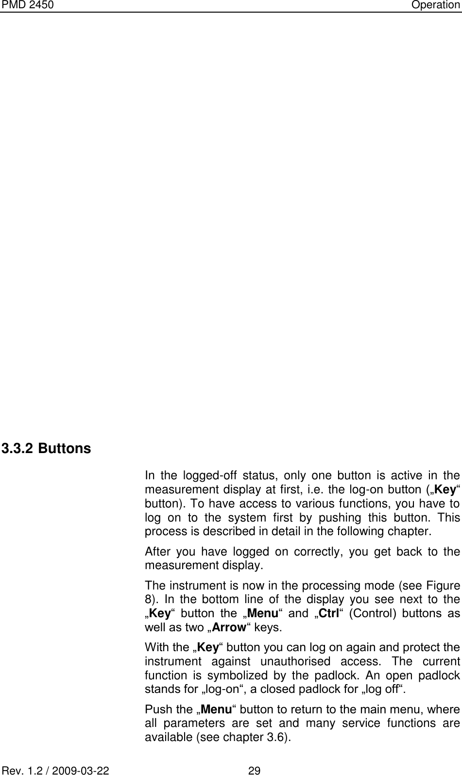
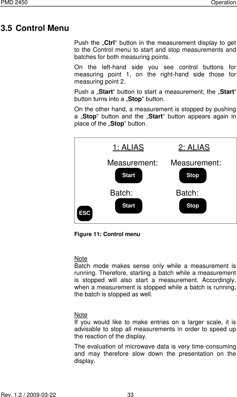
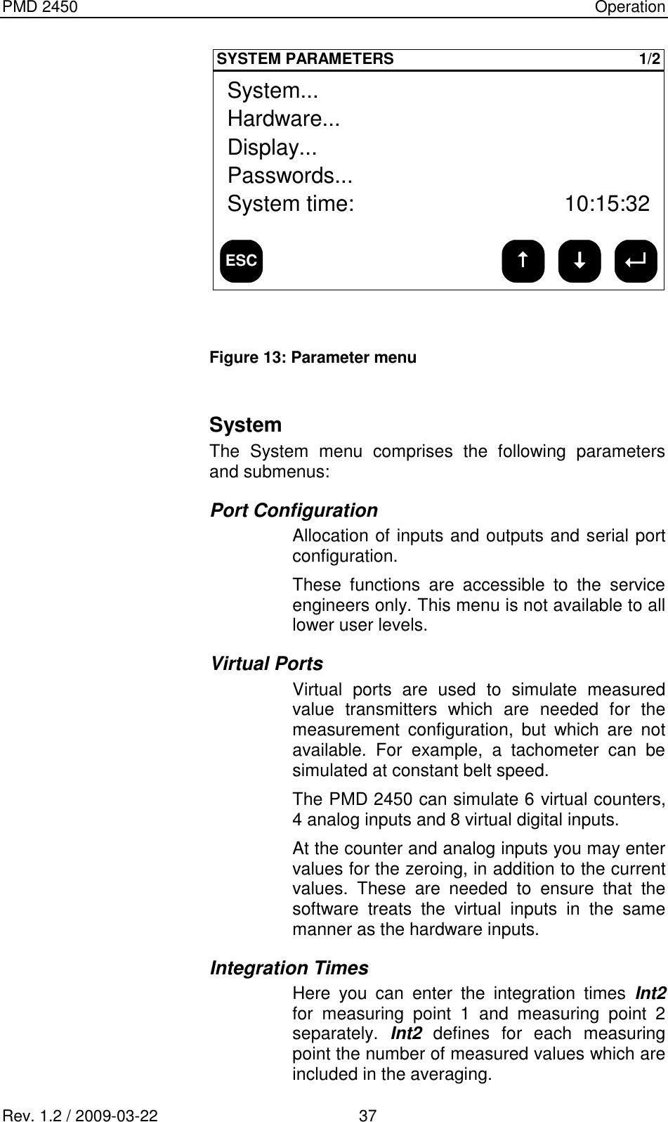
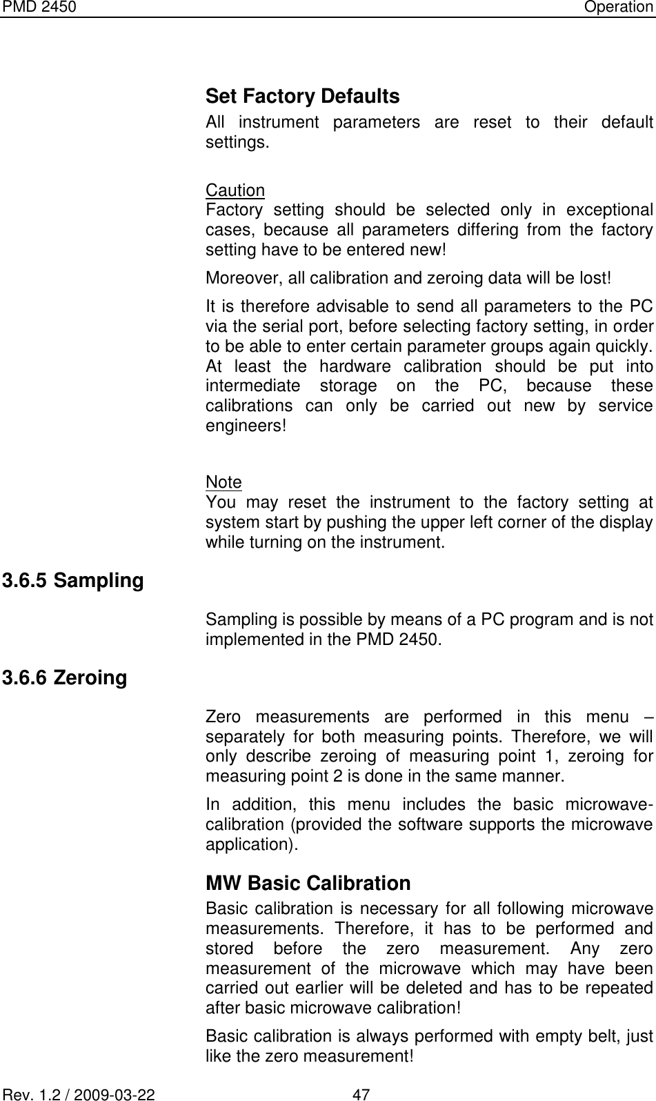
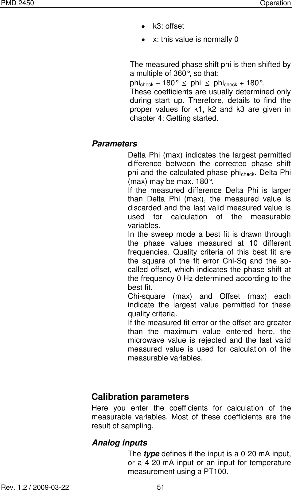
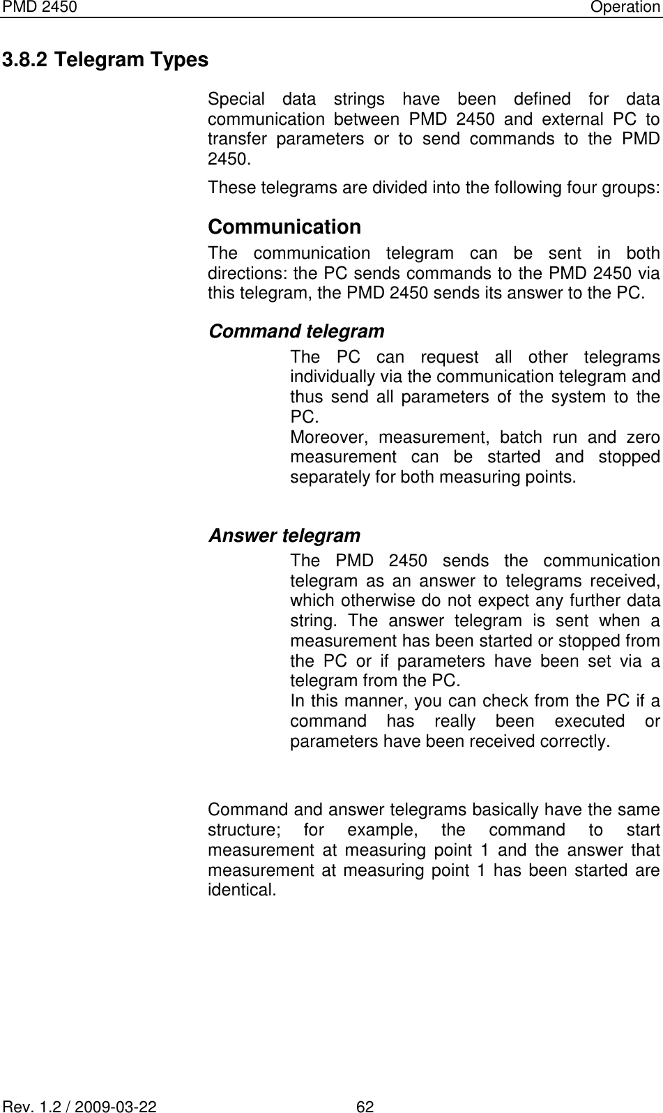
![PMD 2450 Operation Rev. 1.2 / 2009-03-22 46 Q2 = ln(I/Io)X / m Q3 = [ ln(I/Io)X ]² / m The factors Q1 – Q3 are inserted in the calculation formula for the ash content. The ash content calculated according to this formula appears at the bottom of this page. Belt weigher data Figure 18 shows the menu for the belt weigher calculation. ESCVIEW BELT WEIGHER MP1R a w d a t a1 : 0 . 02 : - - -3 : - - -4 : - - -5 : - - -l n ( I / I o )1 : 0 . 02 : - - -3 : - - -4 : - - -5 : - - -A v e r a g e:0 . 0T a c h o : 0 . 0B e l t w . : 0 . 0 Figure 18: View Belt weigher data menu Up to 5 measuring paths can be installed vertically to the belt moving direction to ensure fairly accurate calculation of the throughput. As with the ash data, the signal flow occurs from left to right. In the left column appear the count rates of the belt weigher counters 1 – 5 averaged over Int2. However, these values serve only for your information and do not enter directly into the calculation of the throughput. The center column shows the natural logarithms averaged over Int2 of the count rates referring to the zero rate, i.e. ln(I/Io)counter 1 to ln(I/Io)counter 5. To the very right you see the mean value of the data in the center column. This value is inserted into the calculation formula to calculate the throughput. Moreover, the belt speed averaged over Int2 appears in this column. At the bottom of this page you see the throughput calculated on the basis of the above data.](https://usermanual.wiki/InduTech-instruments/PMD2450-2/User-Guide-1565946-Page-52.png)
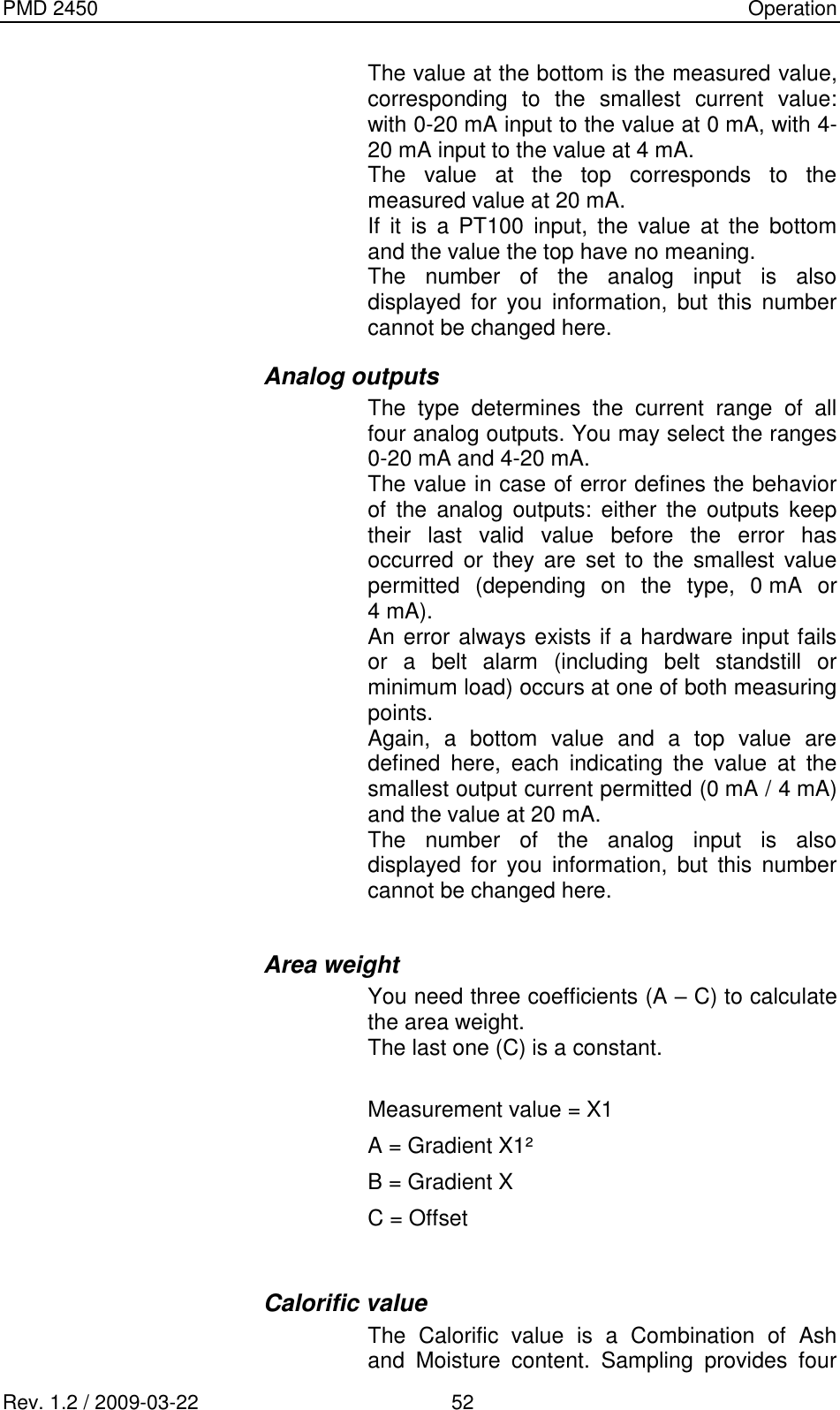
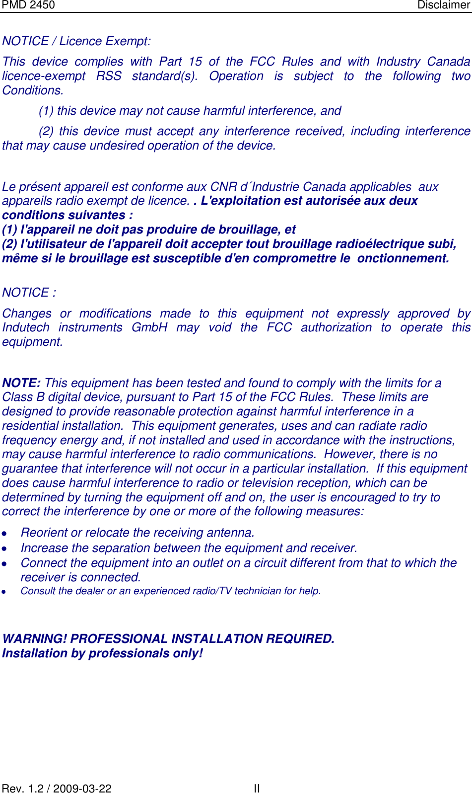
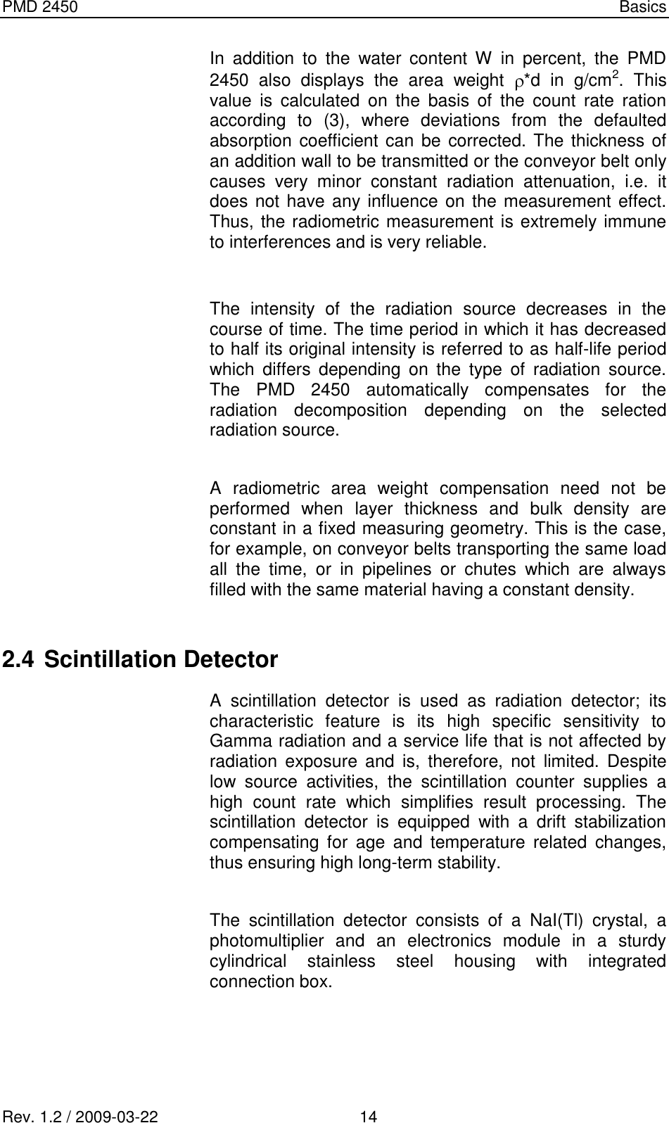
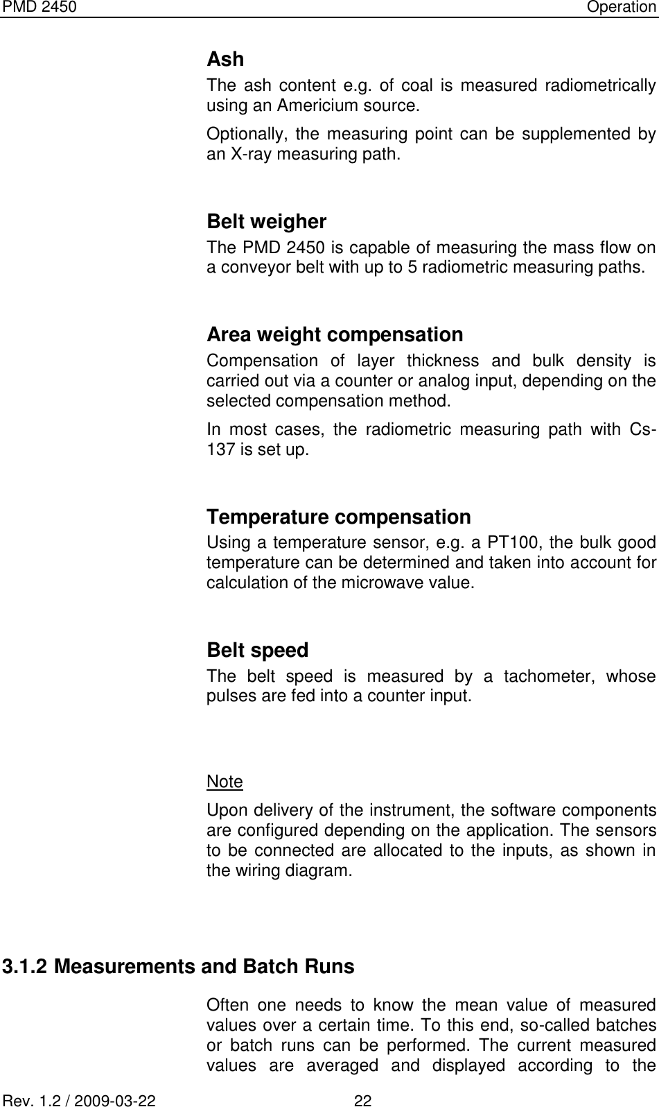
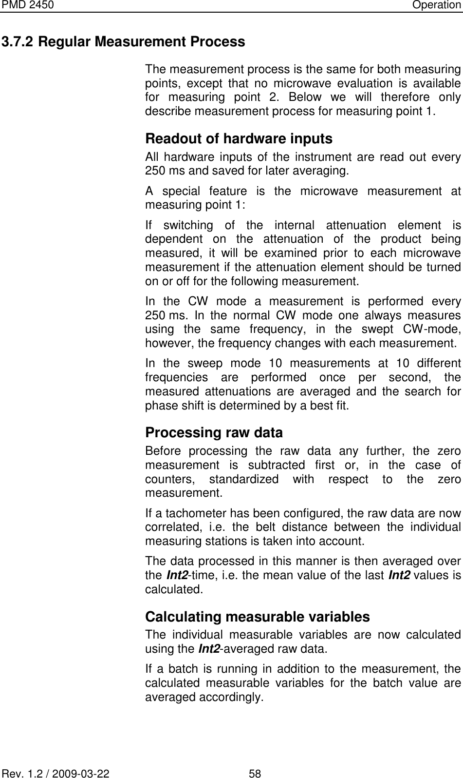
![PMD 2450 Operation Rev. 1.2 / 2009-03-22 55 the potassium content. Coefficient D is a constant. MW-Value 1 and 2 From the microwave raw data attenuation and phase one can determine different measurable variables, such as moisture content, pH-value, salt content and others. Under MW measured value you may therefore select from a list which physical variables are to be calculated with the following coefficients. This name then appears in the measurement display instead of the term „MW-value“. There are eight coefficients (A – H) for calculation of the desired microwave value; coefficient H is a constant. For compensation of the material temperature as well as for ash compensation, enter the value determined during sampling under mean value material temperature or mean value ash. Alarm Meas. Values Here you can define a lower and upper alarm threshold for each measurable variable. In this manner you may set a window for each measurable variable, within which the measured value should lie. Moreover, you may enter a switching hysteresis in % for each measurable variable. The lower alarm will be reset only when the measured value exceeds the value (1 + hysteresis[%] / 100) * limitlow. Accordingly, the upper alarm is reset only when the measured value drops below the value (1 - hysteresis[%] / 100) * limithigh. A digital output can be assigned to each alarm. These outputs are wired such that a relay connected to them](https://usermanual.wiki/InduTech-instruments/PMD2450-2/User-Guide-1565946-Page-61.png)
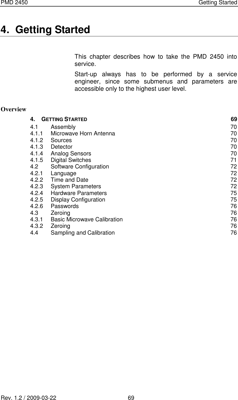
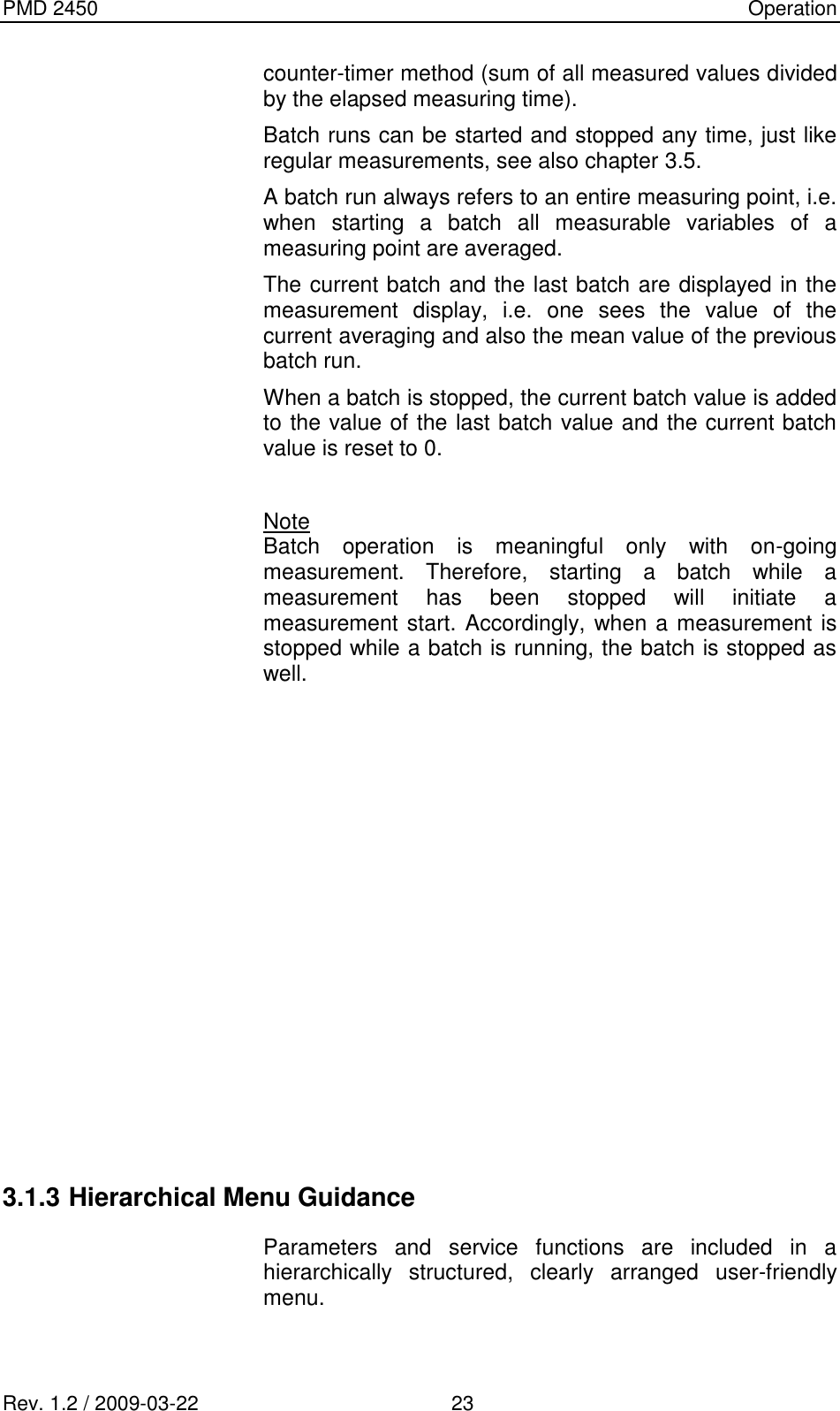
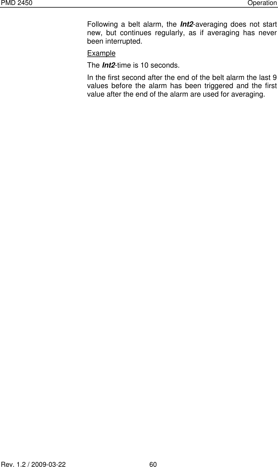
![PMD 2450 Operation Rev. 1.2 / 2009-03-22 56 picks up during operation and is released if an alarm is triggered. Alarm Belt A belt alarm occurs if either the minimum load or the minimum speed of the belt is not reached. In this menu you can define a minimum load as well as a minimum speed. Again, there is also a switching hysteresis, so that the belt alarm will be reset only when the value (1 + hysteresis [%] / 100) * limitlow is exceeded. With active belt alarm, the measurement continues to run; however, averaging over the Int2-time is stopped and continues only after the belt alarm is over. Therefore, the measured value does not change during belt alarm. Following a belt alarm, the Int2-averaging does not start new, but continues regularly, as if averaging has never been interrupted. Example The Int2-time is 10 seconds. In the first second after the end of the belt alarm the last 9 values before the alarm has been triggered and the first value after the end of the alarm are used for averaging.](https://usermanual.wiki/InduTech-instruments/PMD2450-2/User-Guide-1565946-Page-62.png)
![PMD 2450 Operation Rev. 1.2 / 2009-03-22 59 Sending a data telegram A data telegram including the current measured values is sent to an external PC every second. In the menu Parameters System (see chapter 3.6.3) you can define if the instrument should send measured raw data or calculated measured data to the PC. Setting hardware outputs After calculation of the measured data, the alarm thresholds are checked and the digital outputs are set accordingly. Moreover, the configured current outputs of the measured values are set accordingly. 3.7.3 Error and Alarm States This chapter briefly describes how the instrument behaves if errors and active alarms occur. Hardware failure Hardware failure occurs when a measured raw value falls below the failure threshold of the respective hardware input. In this case a collective failure message may be generated and output as error to a digital output. Measurements continue to run, however, until they are stopped manually. Alarm of measurable variable A lower and upper alarm threshold defining a measurement display can be entered for each measurable variable. If the measured value is outside this permitted range, an alarm is triggered which can be sent to a digital output. Belt alarm A belt alarm occurs if either the minimum load or the minimum speed of the belt is not reached. As with the alarm thresholds of the measurable variables, there is also a switching hysteresis, so that the belt alarm will be reset only when the value (1 + hysteresis [%] / 100) * limitlow is exceeded. With active belt alarm, the measurement continues to run; however, averaging over the Int2-time is stopped and continues only after the belt alarm is over. Therefore, the measured value does not change during belt alarm.](https://usermanual.wiki/InduTech-instruments/PMD2450-2/User-Guide-1565946-Page-65.png)
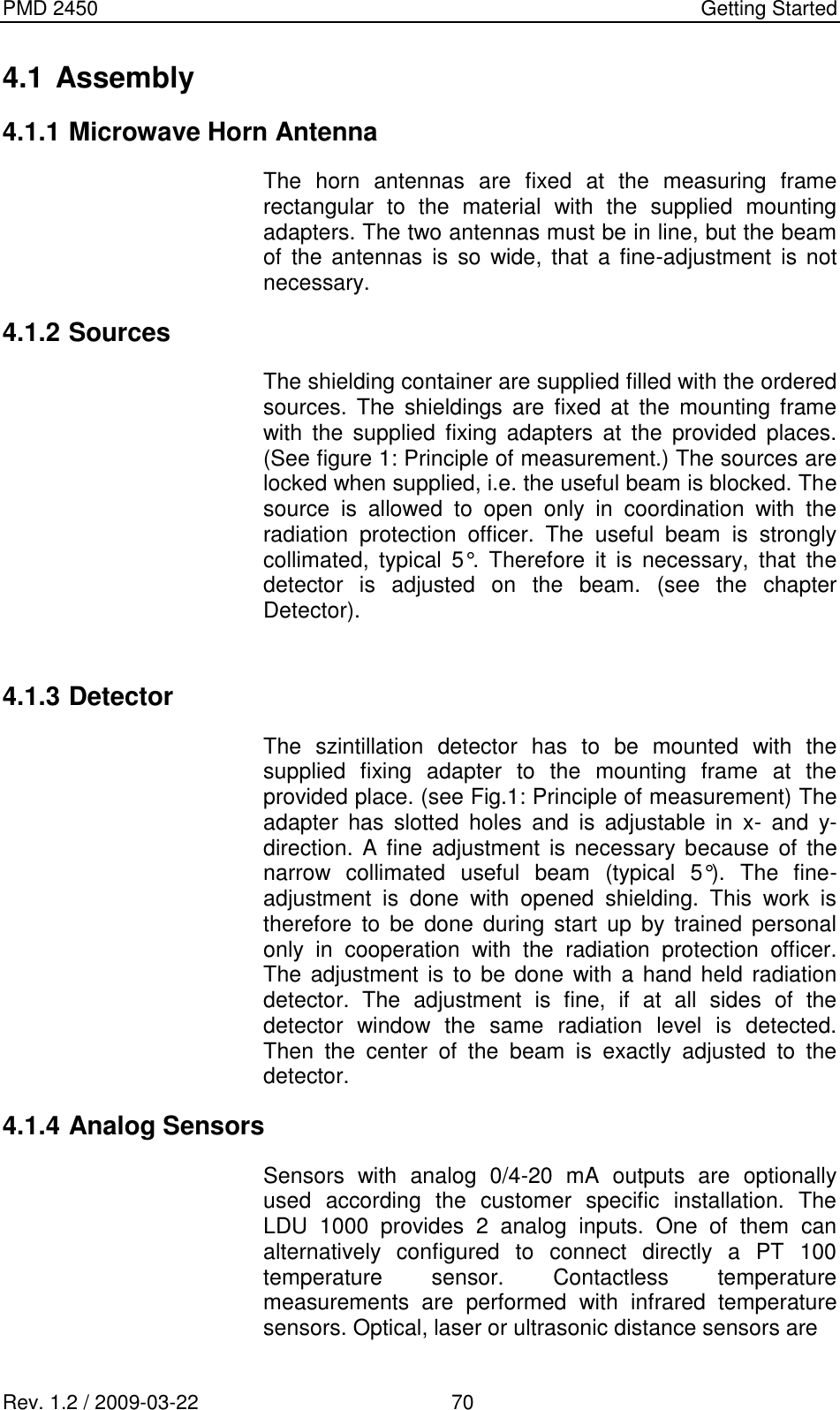
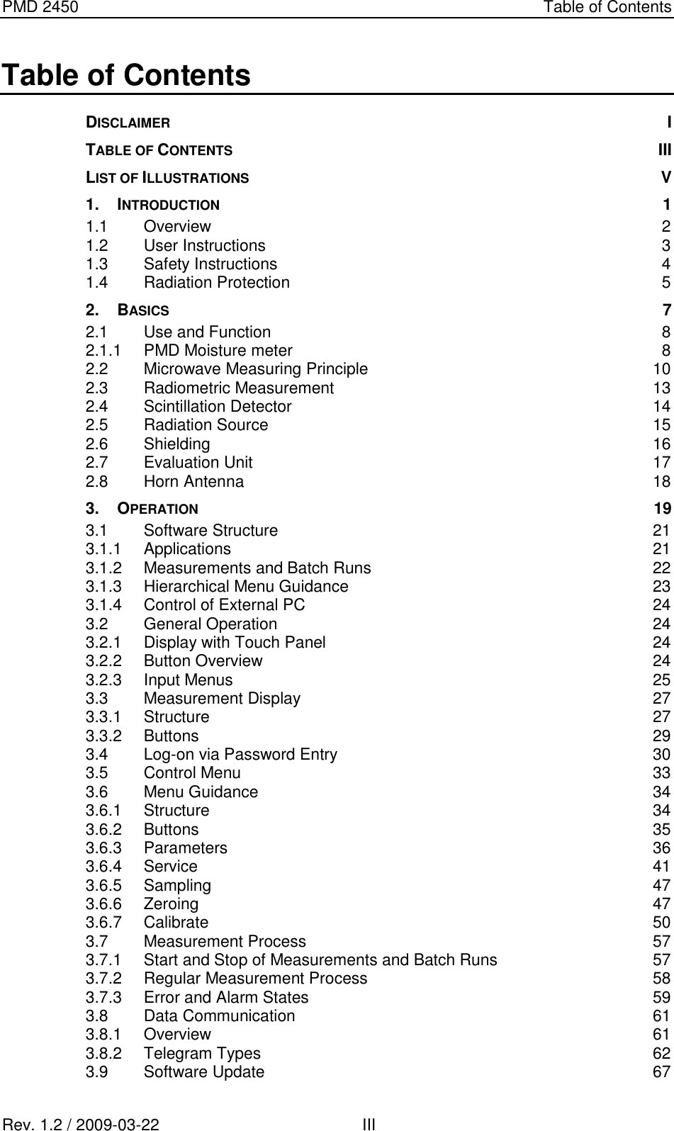
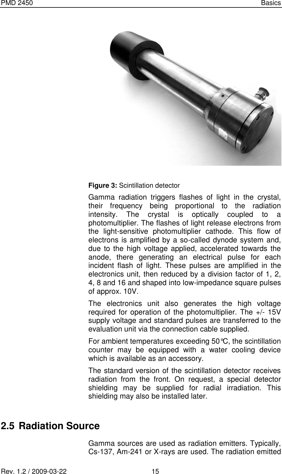
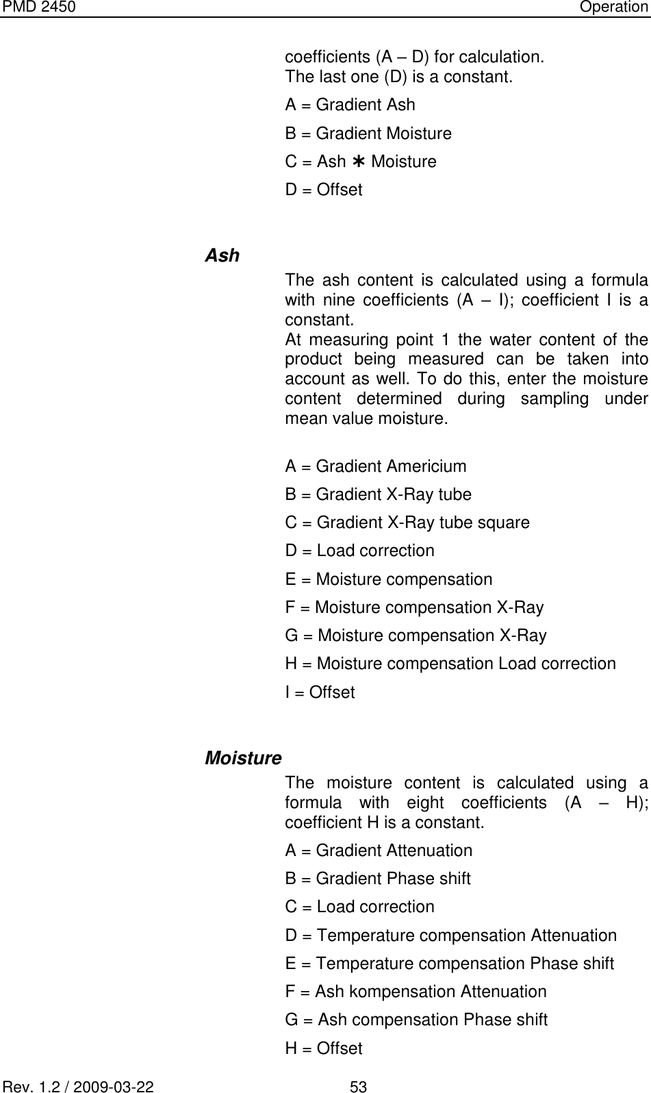
![PMD 2450 Operation Rev. 1.2 / 2009-03-22 66 Frequency response The content if the telegram is: telegram adress telegram adress frequeny [Mhz] attenuation [dB] attenuation*f(x) Phi [°/Ghz] PhiCheck [°/GHz] Delta (Phi-PhiCheck) [°] area weight Analog outputs This telegram allows you to set the analog output directly from the PC. However, this is allowed only if the analog output is not used by the measurement routine! Value of analog output 1 Value of analog output 2 Value of analog output 3 Value of analog output 4](https://usermanual.wiki/InduTech-instruments/PMD2450-2/User-Guide-1565946-Page-72.png)