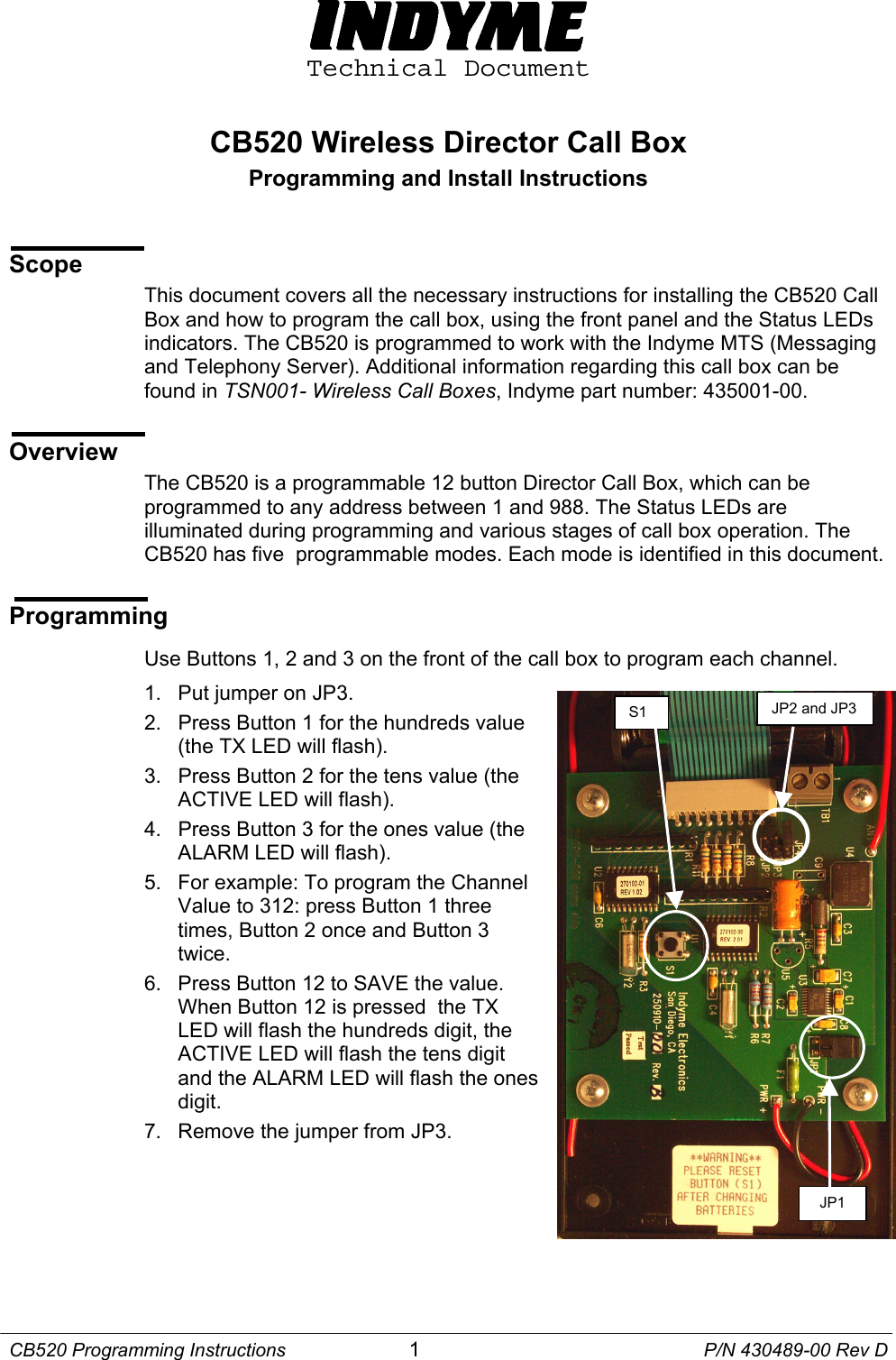
Indyme Solutions CB520 Wireless Director Call Box User Manual CB520 Wireless Director Call Box

Indyme Solutions, Inc Wireless Director Call Box CB520 Wireless Director Call Box

Contents

Users manual

 Technical Document  CB520 Wireless Director Call Box Programming and Install Instructions   Scope This document covers all the necessary instructions for installing the CB520 Call Box and how to program the call box, using the front panel and the Status LEDs indicators. The CB520 is programmed to work with the Indyme MTS (Messaging and Telephony Server). Additional information regarding this call box can be found in TSN001- Wireless Call Boxes, Indyme part number: 435001-00.  Overview The CB520 is a programmable 12 button Director Call Box, which can be programmed to any address between 1 and 988. The Status LEDs are illuminated during programming and various stages of call box operation. The CB520 has five  programmable modes. Each mode is identified in this document.   Programming  Use Buttons 1, 2 and 3 on the front of the call box to program each channel. 1.  Put jumper on JP3.  JP2 and JP3 S1 2.  Press Button 1 for the hundreds value  (the TX LED will flash). 3.  Press Button 2 for the tens value (the ACTIVE LED will flash). 4.  Press Button 3 for the ones value (the ALARM LED will flash). 5.  For example: To program the Channel Value to 312: press Button 1 three times, Button 2 once and Button 3 twice. 6.  Press Button 12 to SAVE the value. When Button 12 is pressed  the TX LED will flash the hundreds digit, the ACTIVE LED will flash the tens digit and the ALARM LED will flash the ones digit. JP1 7.  Remove the jumper from JP3.   CB520 Programming Instructions  1  P/N 430489-00 Rev D
Indyme Electronics, Inc.  Programming Mode and House Code. Use Button 1 to select the Mode and use Button 7 to set the House Code. When finished, use Button 12 to SAVE the programmed Mode and House code.  1.  Put jumper on JP2.(JP2 is located right next to JP3) 2.  Press Button 1 to select which mode.       (One press for mode 1, twice for mode 2,         three times for mode 3 and four times for mode 4.) 3.  Press Button 7 to select which house code set. (One press for house code set 1, press twice for House Code set 2.) 4.  Press Button 12 to save the programmed Mode and House Code. The TX LED will flash which mode the CB520 was programmed for and the CLEAR LED will flash which house code set has been selected. 5.  Remove the jumper from JP2. Setting the Normally Open / Normally Closed Jumpers 1.  To set for normally open remove the jumper from JP4. 2.  To set for normally closed put the jumper on JP4.  When either of the above is done, the CB520 must be reset by powering down the call box (removing the jumper from JP1) and then powering it back up and pressing S1. Modes of Operation •  Mode 1 - Director Call Box with 15 Second Time-out (similar to CB514-3) Press a channel button to trigger alarm state; the TX and ACTIVE LED flash. The ACTIVE LED continues to flashes for approximately 15 seconds, then extinguishes with no reset sent.  If the channel button is pressed again within a preset (variable) time the ACTIVE LED will flash for another 15 seconds and the alarm will escalate to the next up-group, depending on the CU4400 programming.  •  Mode 2 - Variable Response Reset (similar to the CB700A mode 5) An external switch contact transition will trigger a button 12 "alarm state" (contact shared with button 12), the ACTIVE LED flashes; and continues to flash for 300 seconds. Pressing any of the other 11 buttons extinguishes the ACTIVE LED, sends a SET transmission for the pressed channel button and a reset transmission for button 12.  •  Mode 3 - Director with External Input and Reset Button 1-11 works the same as Mode 1 (normal director function). The external input is enabled and when triggered, sends a shopper call box transmission for button 12. The ALARM LED comes on solid for one second and the ACTIVE LED flashes at a decreased rate (continues to flash for 300 seconds). If the alarm state is removed, the CLEAR LED will come on solid for one second with no reset sent. Pressing button 12 sends a reset transmission for button 12 and extinguishes the ACTIVE LED (if lit). CB520 Programming Instructions  2  P/N 430489-00 Rev D
Indyme Electronics, Inc.  CB520 Programming Instructions  3  P/N 430489-00 Rev D  •  Mode 4 - CU3000 Backwards Compatible Mode 4 is basically Mode 1 without Supervisory TX. This mode is backwards compatible with CU3000 systems.  **Note: to work with a CU3000,  the DAT file will need to be modified.  Button mapping is slightly different than the CB500A.**  •  Mode 5 – Variable Response with Acknowledge An external switch contact transition will trigger a button 12 "alarm state" (contact shared with button 12), the Active LED flashes and continues to flash for 300 seconds. For example: when Button  1 is designated as the Acknowledge Button, pressing Button 1 also acknowledges Button 12, the Active LED flashes at a faster rate and continues to flash for 300 seconds.  Buttons 2-11 are designated as Reason Buttons and send a set transmission for the button pressed. This mode must be used with the CB520-ACK script to associate the correct reason code with the original alarm.   Installation The CB520 call box arrives with two Velcro strips affixed to the back of the call box. To mount the call box, thoroughly clean the mounting surface with alcohol, removing all dirt from the mounting surface. Remove the tape from the Velcro strips and press the call box firmly into position – typically located near a register or telephone at a checkout counter or service desk.        FCC Notice Of Compliance: This equipment complies with Part 15 of the FCC Rules. Any changes or modifications not expressly approved by the manufacturer could void the user's authority to operate the equipment.

Navigation menu