Indyme Solutions CB529A Director Call Box User Manual CB514 Install and Test Procedure
Indyme Solutions, Inc Director Call Box CB514 Install and Test Procedure
User Manual
Technical Document
CB529A Program & Install Instructions 1 P/N 430721-00 Rev C
CB529A
CB529A Programming and Installation Instructions
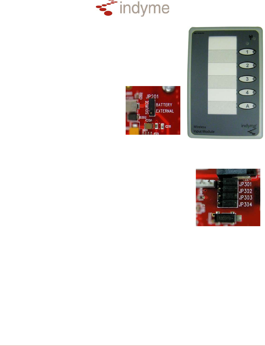
The CB529A is a special purpose, multi-function call box. It is designed for
use as a director, shopper and/or external contact call box. The CB529A
contains 4-inputs, each input can be configured for use as a normally
opened or normally closed contact. The contacts can be configured
individually or globally. The CB529A must be correctly configured and
programmed to operate with external devices. Identify the quantity and types
of circuits you will be using prior to beginning installation.
Call Box Jumpers
The CB529A requires +3VDC to operate. Power
can be supplied via 2-C size batteries or an
external +12VDC power supply. Using JP201,
select the desired power source by placing the
jumper over the two corresponding pins.
Removing the jumper or placing it on one pin of
JP201 will disable the call box.
The CB529A has 4-inputs, each input has a jumper used to assign the circuit type, normally opened (NO) or
normally closed (NC). Using the jumpers labeled, JP301- JP304, set the circuit type for each input. Placing a
jumper over both pins on the right, or removing the jumper, assigns a normally opened input. Placing a jumper
over both pins on the left assigns a normally closed input. (The picture at right
indicates all inputs configured for normally opened inputs.)
Call Box Programming
The CB529A uses a hierarchy based menu structure. Programming requires a
series of button presses to access each menu. Using button-1 to SET, button-
A to RESET and the button-1 assurance LED, program the following menu
options.
Enter Programming Menu
Press and hold the RESET button (approx. 8-sec) until the assurance LED blinks once.
Press and hold the SET button (approx. 8-sec.) until the assurance LED blinks twice.
Press and hold the RESET button (approx. 8-sec.) until the assurance LED blinks three times.
Proceed to the desired menu.
Menu-1: Address Programming -used to assign an alarm address to a call box. The address will
define which message(s) are broadcast when the call box is activated. The valid address range is from
001 to 999. Leading zeros are required. The default alarm for all call boxes is alarm-001.
(Example: Alarm-107)
After entering the Programming Menu;
Press the SET button once, RESET once. The assurance LED will flash once to confirm your
entry. You are now in Menu-1.
Enter your address as follows.
Press the SET button once, RESET once to save. (1)
Press the RESET button once to represent the zero. (0)
Press the SET button seven times, RESET once to save. (7)
PRE-RELEASE

Technical Document
CB529A Program & Install Instructions 2 P/N 430721-00 Rev C
When the last digit is saved, the assurance LED will confirm your entry by flashing to indicate the digits
entered. A zero is indicated by a long flash of approximately 1-second.
Call box buttons-2-4 are automatically assigned the next consecutive alarm numbers. They cannot be
programmed independently.
Menu-3: Global Input Mode -used to assign operational characteristics to all inputs globally. The
operational characteristics define how the call box will respond to button presses, input triggers and
timing parameters.
After entering the Programming Menu;
Press the SET button 3-times, RESET once to save.
The assurance LED will flash three times to confirm your entry. You are now in Menu-3.
Press the SET button <1--6> times to select the Operating Mode, RESET once to save.
The assurance LED will flash to confirm your entry.
Menu-11: Individual Input Mode -used to assign operational characteristics to each input individually.
The operational characteristics define how the call box will respond to button presses, input triggers
and timing parameters.
After entering the Programming Menu;
Press the SET button 11- times, RESET once to save.
The assurance LED will flash eleven times to confirm your entry. You are now in Menu-11.
Press the SET button <1–4> times to select the input you are programming, RESET once to
save. The assurance led will flash to confirm your entry.
Press the SET button <1–4> times to select the Operating Mode, RESET once to save.
The assurance LED will flash to confirm your input number, pause, then flash to confirm your
Operating Mode entry.
NOTE: Operating Modes <5--6> are NOT valid for Individual Input Mode.
When Operating Modes <5--6> are set globally, Individual Input Mode is disabled.
Operating Modes
Mode-1: Alarm Notify Non-Latching
Basic alarm notification; compatible with “Shopper Call Box” alarm processing.
When any INPUT is activated, an alarm SET is broadcast and the corresponding LED will flash
according to “LED Sequence 1”. (Indicated below.)
When the INPUT is deactivated, an alarm RESET is broadcast and the corresponding LED will turn off.
Mode-2: Alarm Notify Latching
Basic alarm notification, response required;
When any INPUT is activated, an alarm SET is broadcast and the corresponding LED will flash
according to “LED Sequence 1”. (Indicated below.)
When the INPUT is deactivated, NO alarm RESET is broadcast. The corresponding LED will continue
to flash until the front panel button is pressed.
Responding user must press the front panel button corresponding to the active INPUT to broadcast an
alarm RESET and turn off the LED. If a front panel button is pressed when the INPUT is not active,
(non-alarm), an alarm RESET is broadcast.
PRE-RELEASE

Technical Document
CB529A Program & Install Instructions 3 P/N 430721-00 Rev C
Mode-3: Alarm Reminder Non-Latching
Same as Mode 1 except, the alarm is re-started if the INPUT is not cleared. Periodically re-starts the
alarm sequence for situations in which a persisting alarm condition may be overlooked (such as an
alarm sequence that starts during unstaffed hours and does not self-clear). If alarm state persists more
than XXX minutes (XXX specified by CU-based variable in the range of 15 to 999 minutes; default is 30
minutes), then repeatedly re-start this sequence from the beginning as a new alarm.
Mode-4: Alarm Reminder Latching
Same as Mode 2 except, the alarm is re-started if the corresponding front panel button is not pressed.
Periodically re-starts the alarm sequence for situations in which a persisting alarm condition may be
overlooked (such as an alarm sequence that starts during unstaffed hours and does not self-clear). If
alarm state persists more than XXX minutes (XXX specified by CU-based variable in the range of 15 to
999 minutes; default is 30 minutes), then repeatedly re-start this sequence from the beginning as a new
alarm.
Mode-5: Director Buttons Latching
Four Button Director Call Box; the four external INPUTS are disabled.
When user presses any of buttons 1 through 4, an alarm SET is broadcast and the corresponding
LED will flash according to “LED Sequence 1”. (Indicated below.) Responding user presses the front
panel button “A” (RESPOND) to clear all active alarm(s); an alarm RESET is broadcast and the
corresponding LED(s) will turn off. If RESPOND button is not pressed within 10 minutes, the call box
terminates “LED Sequence 1” and the alarm will timeout.
Mode-6: Alarm Notify & Director Latching
Provides a combination of External Inputs and Director Buttons:
INPUTS 1 and 2 operate in Mode 2; the corresponding front panel button must be pressed to RESET.
Buttons 3 and 4 operate in Mode 5; button “A” is used to RESET active alarms on Buttons 3 & 4.
LED Sequence-1
x LED lights solid for the duration that the input alarm exists for a maximum of 5 seconds.
x LED continues flashing rapidly for 2-minutes.
x LED continues flashing in short bursts indefinitely.
x LED ends the flash sequence with two long flashes, then extinguishes when:
Non-latching Operating Modes - the alarm condition clears.
Latching Operating Modes – when associated RESET is pressed, (if the input alarm condition is
clear).
PRE-RELEASE
Technical Document
CB529A Program & Install Instructions 4 P/N 430721-00 Rev C
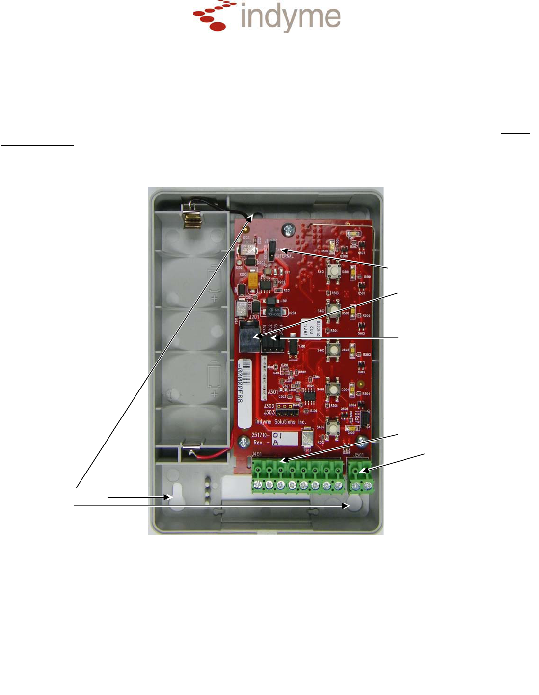
Wiring and Installation
Insure the call box is correctly programmed before installing wiring or mounting the call box. Install the two
green terminal blocks onto the pins of J401 and J501 respectively. J401 contains 4-pairs of screw terminals
corresponding to inputs 1-4. J501 has 1-pair of screw terminals, this connection is not used. Insert the wires
through the hole in the back of the call box. Insert each wire into the corresponding input screw terminal; inputs
1-4, left to right. Secure the wires by tightening the screws. Verify the power jumper JP201 is installed and the
corresponding power source is installed/connected. Test the call box for proper operation before final
installation.
J401: Input Terminals 1- 4
J501: NOT USED
JP201: Power Source Jumper
J201: External Power Jack
JP301--304:
Input Circuit Jumpers
Mountin
g
Holes
Using the installation hardware provided, install the call box in a secure location. Ensure the wires are properly
secured and will not pull out of the call box.
DO NOT MOUNT THE CALL BOX IN OR NEAR THE FOLLOWING;
Moist or damp environments.
Radio Frequency devices that may interfere with call box signals.
Outdoors or exposed to outdoor elements.
Excessive vibration which may cause wires to come loose.
PRE-RELEASE

Technical Document
CB529A Program & Install Instructions 5 P/N 430721-00 Rev C
FCC Notice of Compliance
This device complies with Part 15 of the FCC Rules. Operation is subject to the following two conditions:
(1) this device may not cause harmful interference, and (2) this device must accept any interference
received, including interference that may cause undesired operation.
The user is cautioned that changes or modifications not expressly approved by the party responsible for
compliance could void the user’s authority to operate this equipment.
This device complies with Industry Canada licence-exempt RSS standard(s). Le présent appareil est
conforme aux CNR d'Industrie Canada applicables aux appareils radio exempts de licence. L'exploitation est
autorisée aux deux conditions suivantes : (1) l'appareil ne doit pas produire de brouillage, et (2) l'utilisateur
de l'appareil doit accepter tout brouillage radioélectrique subi, même si le brouillage est susceptible d'en
compromettre le fonctionnement.
Class B statement:
This equipment has been tested and found to comply with the limits for a Class B digital device, pursuant to
part 15 of the FCC Rules. These limits are designed to provide reasonable protection against harmful
interference in a residential installation. This equipment generates, uses and can radiate radio frequency
energy and, if not installed and used in accordance with the instructions, may cause harmful interference to
radio communications. However, there is no guarantee that interference will not occur in a particular
installation. If this equipment does cause harmful interference to radio or television reception, which can be
determined by turning the equipment off and on, the user is encouraged to try to correct the interference by
one or more of the following measures:
—Reorient or relocate the receiving antenna.
—Increase the separation between the equipment and receiver.
—Connect the equipment into an outlet on a circuit different from that to which the receiver is connected.
—Consult the dealer or an experienced radio/TV technician for help.
PRE-RELEASE