Indyme Solutions CB929A help button or call box User Manual CB514 Install and Test Procedure
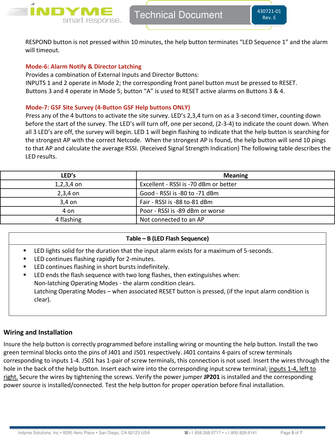
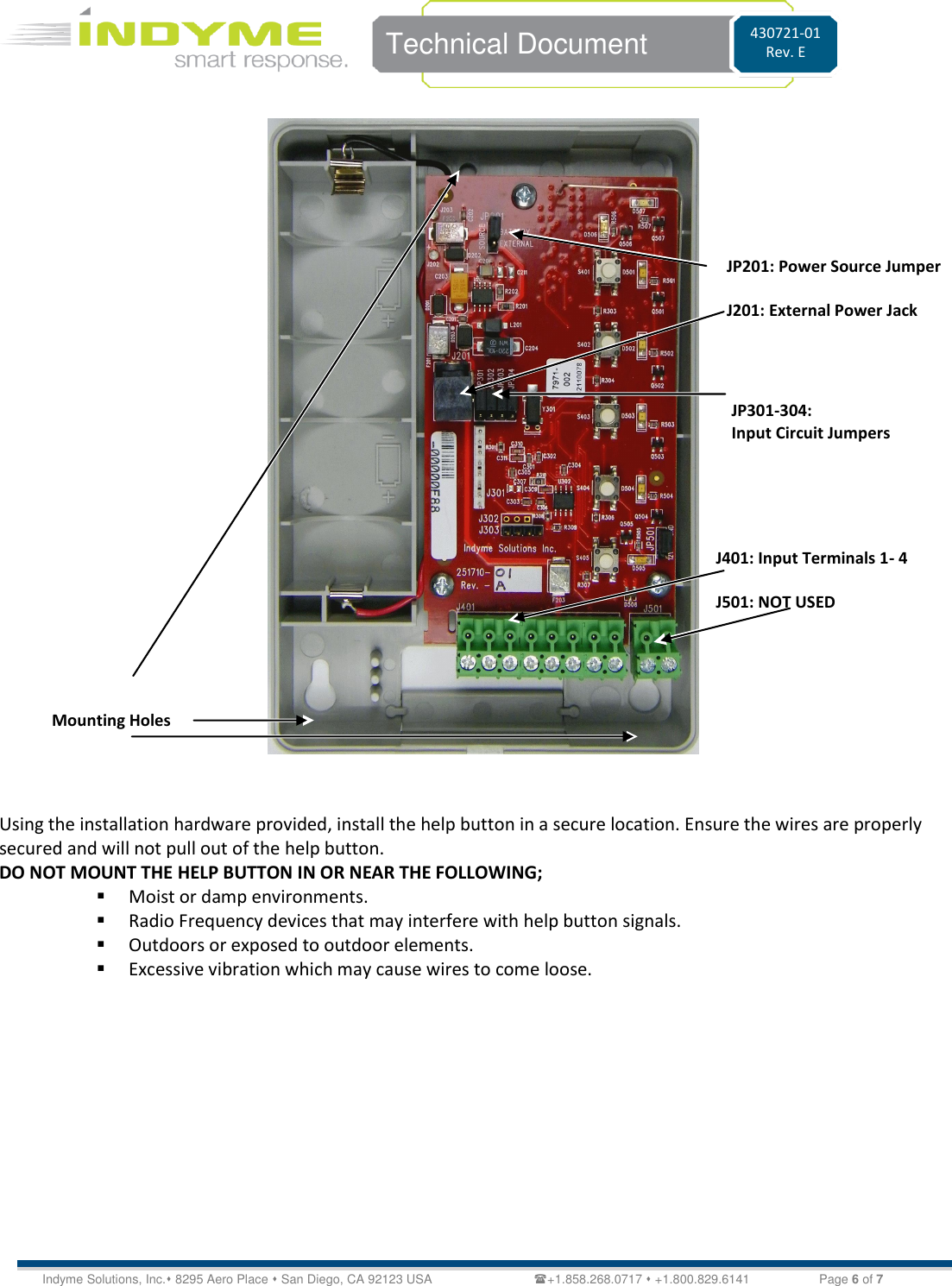
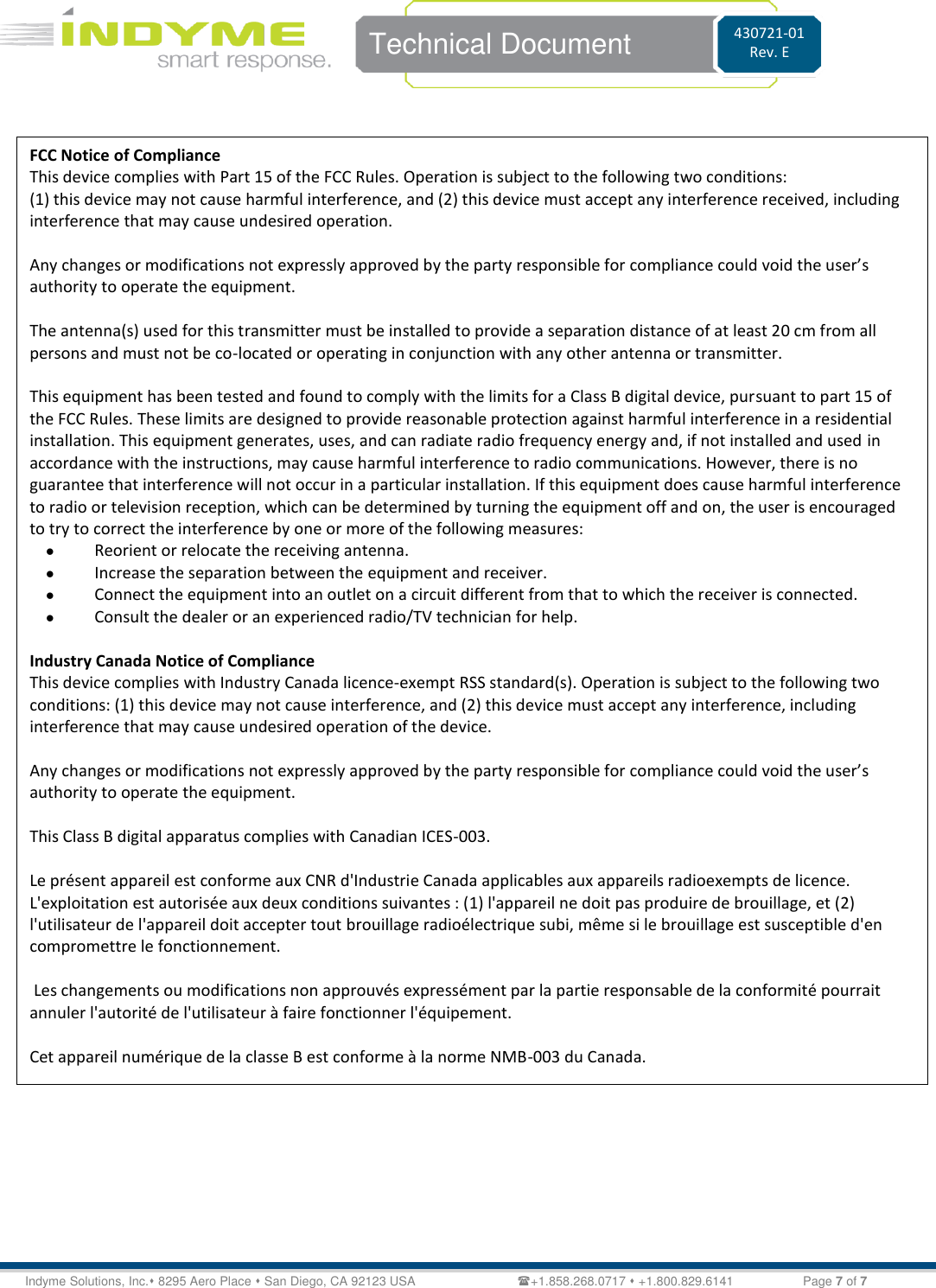
Indyme Solutions, Inc help button or call box CB514 Install and Test Procedure
UserManual.wiki
>
Indyme Solutions
>
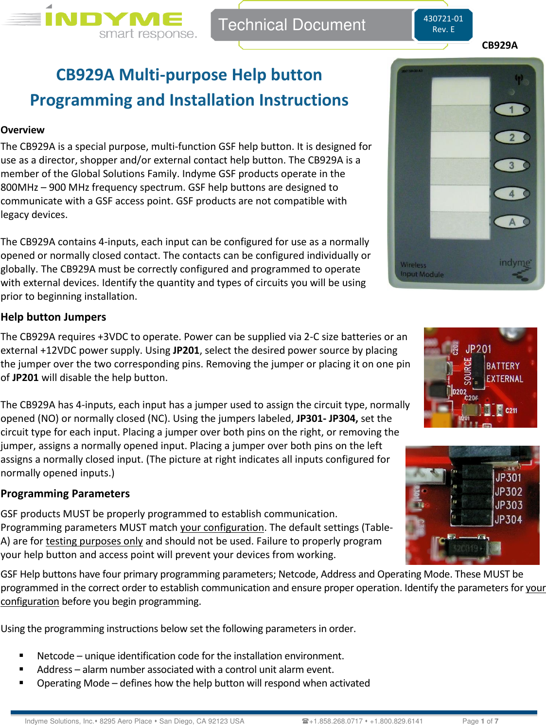
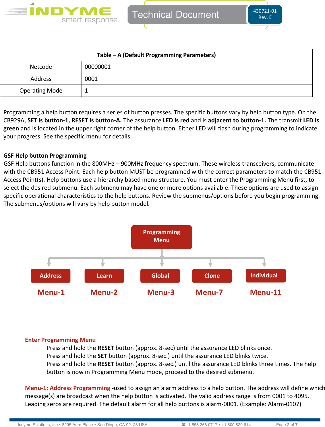
CB929A User Manual
User Manual
Navigation menu
Upload a User Manual
Namespaces
Wiki Guide
HTML
PDF
Info
Views
User Manual
Discussion / Help
Navigation