Indyme Solutions CB951 Wireless Access Point User Manual CB451C Installation Guide
Indyme Solutions, Inc Wireless Access Point CB451C Installation Guide
user manual
Technical Document
CB951 Installation Guide Page 1 P/N 430697-00 Rev C
CB951 Access Point Installation Guide
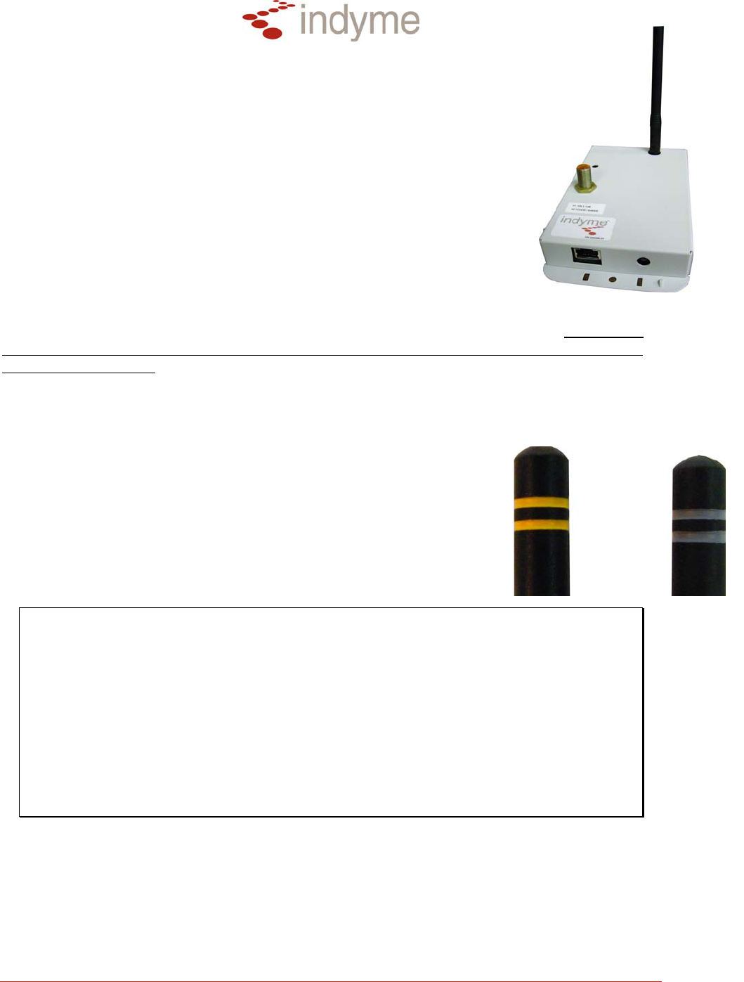
The CB951 is a multi-band access point designed to decode radio frequency
transmissions from any of Indyme’s multi-band wireless callboxes. The
signals are relayed, via the LAN, to an Indyme server for processing.
Connections to the CB951 will vary depending on the deployed
configuration. The CB951 can be programmed to function in the 868MHz or
900MHz frequency spectrum. Check your configuration for details.
Installation
The CB951 Access Point is a ceiling-mounted device. Plan the installation
such that each unit has the clearest possible “line-of-sight” to the largest possible expanse of
the sales floor. The CB951 Access Point must be programmed before installation. Confirm the
correct antenna is installed and all operational parameters have been set prior to installing the
CB951 Access Points. Each unit will require power; this can be supplied via P.O.E. or external
power supply to each unit. (12VDC, 500mA, positive tip, 2.5mm – SOLD SEPARATELY).
Tools Needed:
• Drill and assorted Drill Bits
• Assorted Screwdrivers (Phillips and Flat Blade)
• Wire Cutters
Equipment Needed:
• CB951 Access Point
• Four (4) pair CAT5 Network Cable
NOTE:
Grey: 868 MHz Europe
Yellow: 900 MHz USA/Australia
* Plan your cable runs to avoid the following potential sources of interference;
DO NOT LAY CABLE ON OR NEAR
Fluorescent lighting fixtures, AC power lines, fan motors or RF transmitters.
* Assure a clear line of sight between the Access Point and installed Callboxes,
avoiding large metallic objects such as storage racks and air ducting.
* Leave at least 15 feet of excess cable at the Access Point location, in the
event that the unit needs to be relocated.
* Do not bundle the cable with other data cables, as “bleed-over” may occur,
causing interference.
Technical Document
CB951 Installation Guide Page 2 P/N 430697-00 Rev C
Position and Install the CB951 Access Point
Depending on the location and the ceiling type, the CB951 Access Point can be mounted on a
beam or through a ceiling tile:
• Tile/Ceiling-mounted CB951: Install the unit above the ceiling tile with the antenna and
LED barrel protruding through the ceiling tile. Verify that the LED barrel and antenna are
visible from the sales floor.
• Open-Beam-mounted CB951: Using zip-ties or hardware, attach the CB951 Access
Point to the bottom of the beam. Verify that the LED barrel and antenna are visible from
the sales floor. Try to mount the Access Point lower than nearby ducting and electrical
conduits.
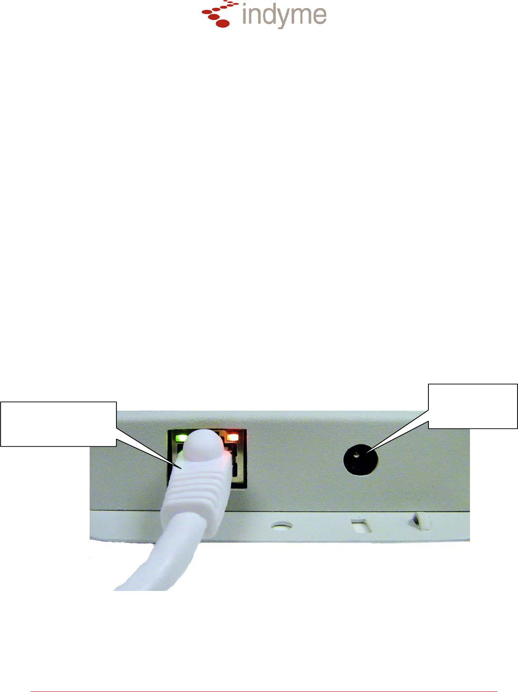
Wiring
The CB951 can be wired using an RJ-45 connector, (568B standard LAN), using CAT5 Network
Cable. The CB951 must be connected using one of the following:
• P.O.E. Switch: Using a CAT5 Network Cable connect one RJ45 to the LAN port on
the CB951 Access Point. Connect the other end of the cable to an available port on
the P.O.E. switch.
• Standard Switch: Using a CAT5 Network Cable connect one RJ45 to the LAN port
on the CB951 Access Point. Connect the other end of the cable to an available port
on the switch. Connect the AC adapter to an available power outlet, connect the
other end to the DC power jack on the Access Point.
To 12VDC
Adapter
(
p
ositive ti
p
)
To network P.O.E.
switch or
Standard switch
CB951 Mounting Template
Depending on the location of the Access Point and the ceiling type, the following template may
be used to accurately mark the holes for the antenna and the indicator L.E.D. The CB951
Access Point can be mounted on a beam or through a ceiling tile.

Technical Document
CB951 Installation Guide Page 3 P/N 430697-00 Rev C
FCC Notice of Compliance: This device complies with Part 15 of the FCC Rules. Operation is subject to
the following two conditions: (1) This device may not cause harmful interference, and (2) This device
must accept any interference received, including interference that may cause undesired operation.
This equipment has been tested and found to comply with the limits for Class B Digital Device, pursuant to
Part 15 of the FCC Rules. These limits are designed to provide reasonable protection against harmful
interference in a residential installation. This equipment generates and can radiate radio frequency
energy and, if not installed and used in accordance with the instructions, may cause harmful interference
to radio communications. However, there is no guarantee that interference will not occur in a particular
installation. If this equipment does cause harmful interference to radio or television reception, which can
be determined by turning the equipment off and on, the user is encouraged to try to correct the
interference by one or more of the following measures.
• Reorient or relocate the receiving antenna
• Increase the separation between the equipment and receiver
• Connect the equipment into an outlet on a circuit different from that to which the receiver is connected
• Consult the dealer or an experienced radio/TV technician for help
Any changes or modifications not expressly approved by the party responsible for compliance could void
the user’s authority to operate the equipment.