Indyme Solutions DM Wireless monitoring system User Manual
Indyme Solutions, Inc Wireless monitoring system Users Manual
Users Manual
Indyme Solutions, Inc. 8295 Aero Place San Diego, CA 92123 USA
+1.858.268.0717 +1.800.829.6141
Page 1 of 10
Install Document 02-19-2016
DM90XX(9021,22,23) Dwell and DM9025 Touch Sensor Installation Guide
Please read these instructions prior to installing the Indyme system.
Introduction
The purpose of this document is to provide
instructions for installation of the DM90XX
(9021,9022,9023) Dwell and DM9025 Touch
Sensors. DM9025 Touch Sensors will be installed
throughout the sales floor. The devices
will
monitor
and report activity with various products
throughout the store. Multi-purpose mounting
hardware is included with each sensor.
Instructions are included on the initial set-up and
installation, removal if needed, and how to
reprogram to another location.
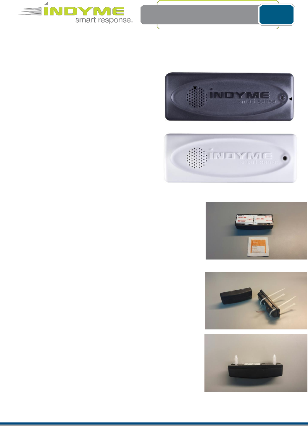
Hardware
SPEAKER
DM9025
LED
Included in the accessory kit
Adhesive mounting pads
Alcohol wipe
Tie cables
Christmas Tree fasteners
Not included
Cutters – if needed during removal
Flathead screwdriver – if needed during removal
Wi-Fi Laptop or Smartphone
Replacement mounting kits are available for one or ten Touch
Sensors. Please call Indyme Solutions to order.
Please refer to page XXX for proper mounting of the device
Indyme Solutions, Inc. 8295 Aero Place San Diego, CA 92123 USA
+1.858.268.0717 +1.800.829.6141
Page 2 of 10
Install Document
02-19-2016
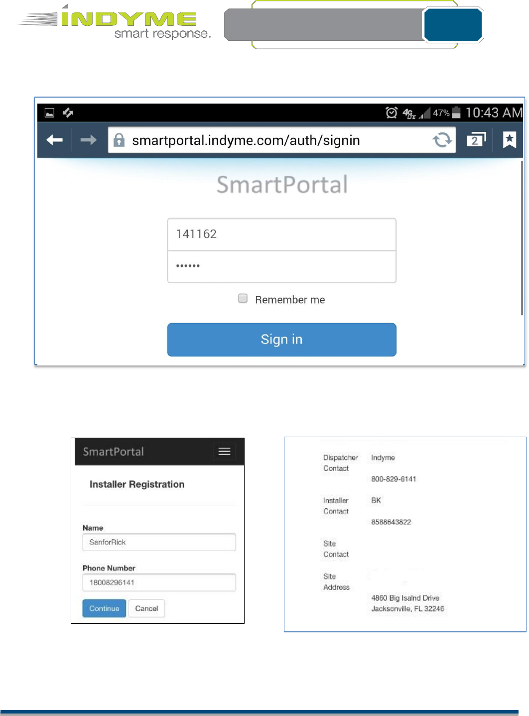
Initial setup – New Touch Sensors
Using the assigned work order for the
store, “Sign In” to the following
website:
www.smartportal.indyme.com
Enter your contact
information and
“Continue”
Verify all information to be correct then tap
Start Work. Make sure the store address
corresponds to the location you’re at.
Indyme Solutions, Inc. 8295 Aero Place San Diego, CA 92123 USA
+1.858.268.0717 +1.800.829.6141
Page 3 of 10
Install Document
02-19-2016
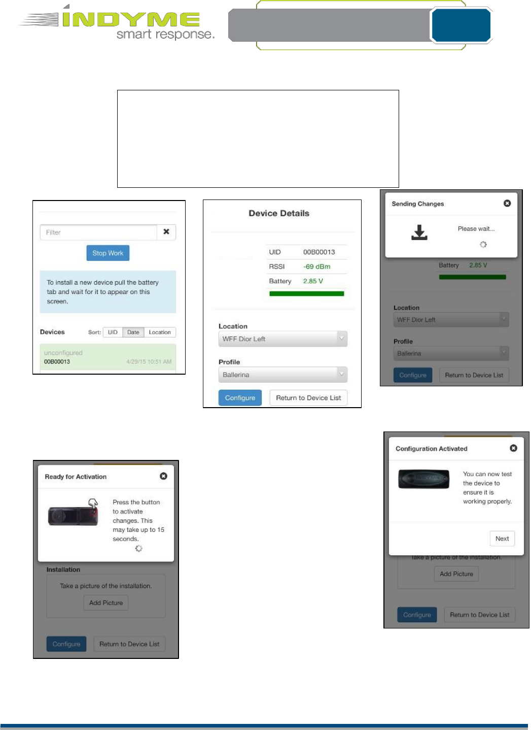
Smart Sense Touch (DM9025)
TEMPORARILY, place the device in the designated
mounting location to test operation and RF signal.
It may be necessary to change this location to ensure
adequate coverage of the product-location.
Follow the steps outlined on the SmartPortal webpage.
Follow the instructions
highlighted in blue to
see the first Touch
Sensor.
Select the appropriate location
for the device. The profile field
will auto populate. Tap
configure.
DO NOT INSTALL THE DEVICE
WITHOUT AN INITIAL TEST. Test the
Touch device in the area where you
plan to mount it.
Indyme Solutions, Inc. 8295 Aero Place San Diego, CA 92123 USA
+1.858.268.0717 +1.800.829.6141
Page 4 of 10
Install Document
02-19-2016
System will prompt you to do 3 things
1. Touch the device and insure it blinks
2. Pull 3 items and ensure the message plays over
the Walkie-talkie.
3. Click next.
4. Take a photo by selecting camera and saving
photo.
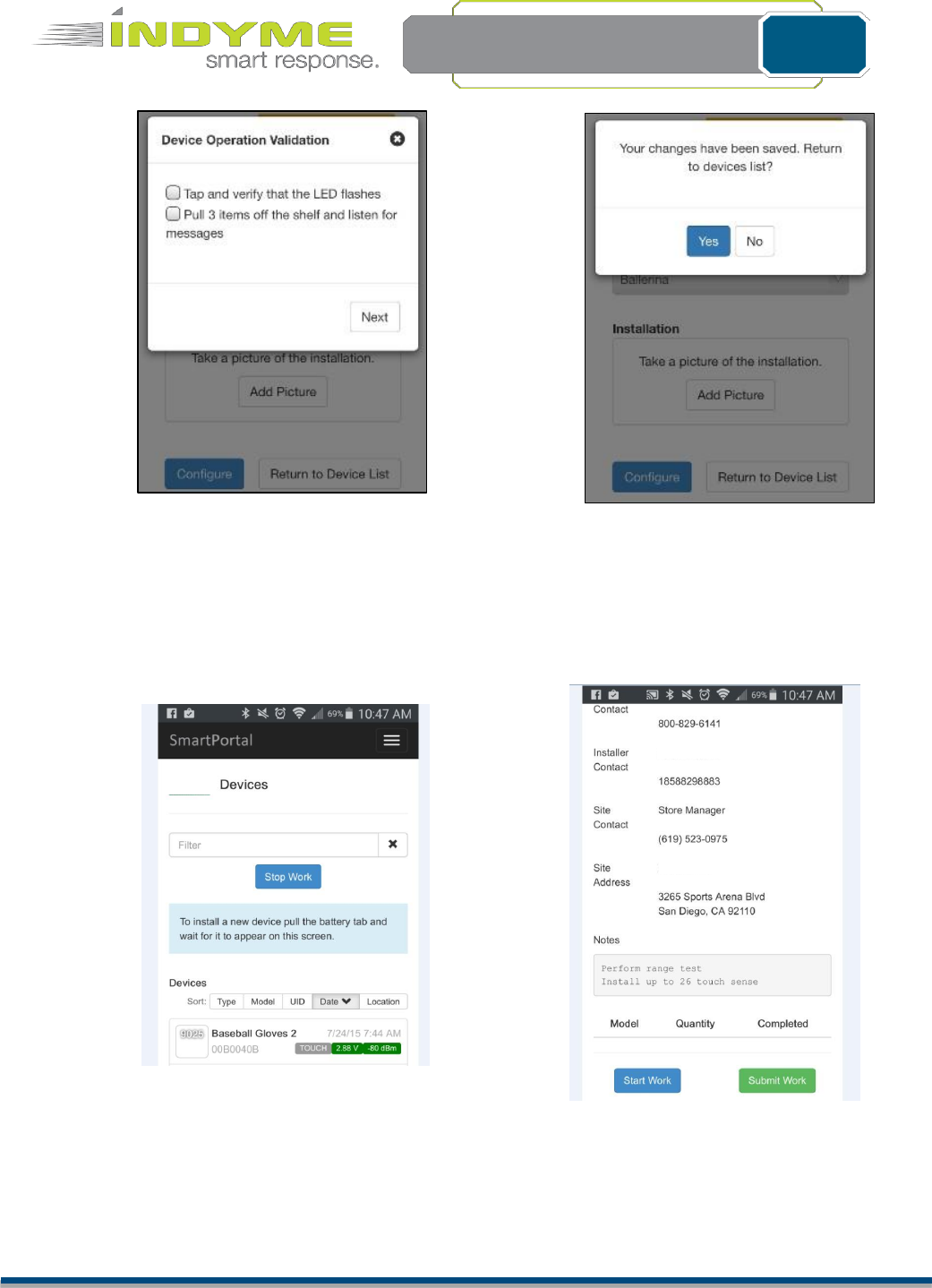
Device will appear on the screen. Continue to next
location and repeat the process until all sensors are
installed.
When all devices are properly installed, click stop work.
When all units have been installed, click
Submit Work.

Indyme Solutions, Inc. 8295 Aero Place San Diego, CA 92123 USA
+1.858.268.0717 +1.800.829.6141
Page 5 of 10
Install Document
02-19-2016
Install the Smart Sense Touch (DM9025)
The DM9025 is a device that monitors suspicious movement on a fixture. Based on the profile (sensitivity)
setting of the device, movement or vibrations will broadcast a message over the desired output device, alerting
associates of suspicious activity.
There are three ways to properly mount the DM9025. The installer can use a Christmas tree fasteners, 3M
adhesive (double-sided tape), or zip ties, all of which are included with each device.
3M adhesive
Use the Sterile Alcohol Prep Pad included with the device to clean the surface, making sure it is smooth and
clear of any small residue that can get on the tape. Attach both pieces of the 3M adhesive to the back plate.
After determining the best orientation for the device, attach it to the cleaned surface and make sure it is secure
and flush.
Removal
To remove the Touch Sensor, slowly pull the device from the surface by its backplate. This will ensure it
stays assembled. Use a flathead screwdriver to help separate the device from the surface as needed.
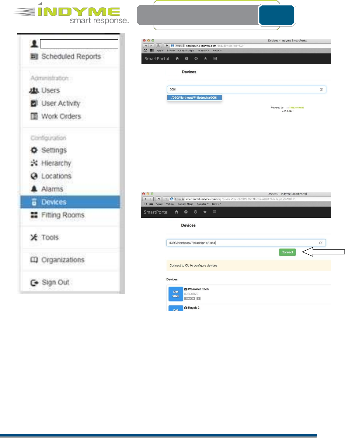
Relocating the Smart Sense Touch (DM9025)
Once the DM9025 Touch Sensor is de-installed, you will be able to move it to a different location.
1- Log into Smart Portal to access your store (reference page 2 for sign-in instructions)
2-
Select
De
v
i
c
es
f
r
o
m
the
“…”
drop down
(see
Figure
1)
3- Select your store (see Figure 2)
4- Select the Connect button to put the system in configuration mode (see Figure 3)
Indyme Solutions, Inc. 8295 Aero Place San Diego, CA 92123 USA
+1.858.268.0717 +1.800.829.6141
Page 6 of 10
Install Document
02-19-2016
Figure 2
Figure 1
Figure 3
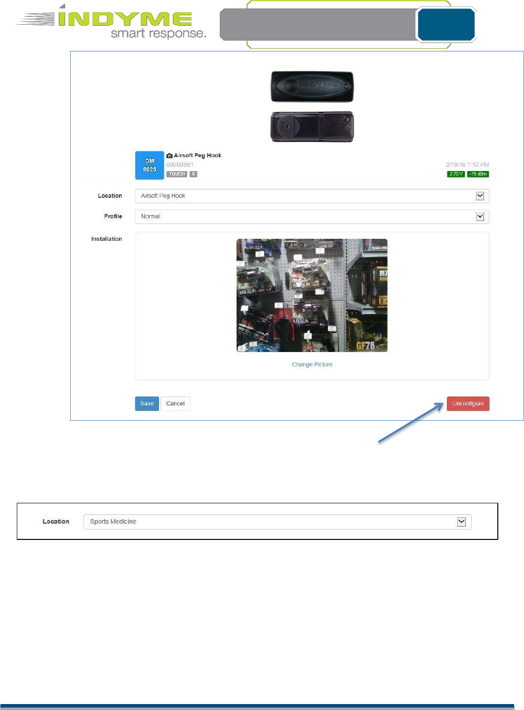
5 - Select the device
6 - Select Unconfigure (see Figure 4). The Touch Sensor is now ready to be programmed to the new
location.
Indyme Solutions, Inc. 8295 Aero Place San Diego, CA 92123 USA
+1.858.268.0717 +1.800.829.6141
Page 7 of 10
Install Document 02-19-2016
Figure 4
7 – Select the device.
8 – Select the new location and save. Press the button on the Touch Sensor for the changes to take
effect. (see Figure 5)
Figure 5
Indyme Solutions, Inc. 8295 Aero Place San Diego, CA 92123 USA
+1.858.268.0717 +1.800.829.6141
Page 8 of 10
Install Document
02-19-2016
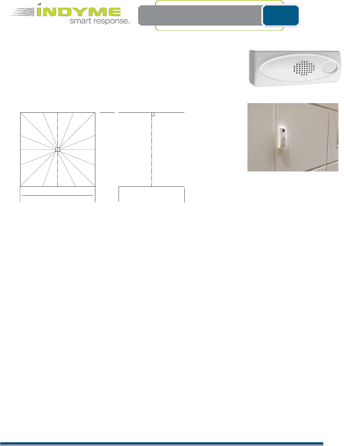
14.0 feet
Top View
14.0 feet
Side View
DM9022 Dwell Devices:
The devices have an infrared motion sensor to monitor and notify associates if a
person is loitering in an aisle. The device is mounted pointed down from in the
ceiling tile.
Dwell device detection window
The dwell devices have a viewing angle of about 90 degrees (45 degrees to each side).
They should be centered above the area of interest
Full/Full Curtain Beam
–
Ceiling Mounted Range Specification
14.0 feet
Mounting DM9022 Dwell Devices
The DM9022 devices have a hingeable rear plate which is used for installation. In a ceiling mount installation,
the hinged plate is opened 90 degrees to allow the provided toggle bolts to be inserted through the two
mounting holes (indicated) and through corresponding holes in the ceiling tile. Never use double sticky tape to
mount DM9022 devices to ceiling tiles.
Once the DM9022 device is secured to the ceiling, the hinge is closed, allowing the device to point straight
down. At this point, the device is ready for SmartPortal installation. You will need to be on the ladder with your
smartphone, computer or tablet connected to SmartPortal in order to complete the installation of a DM9022
device.
SmartPortal installation of DM9022 Dwell Devices
1)
F
ol
l
o
w
the
f
i
r
s
t
4
i
ns
tr
uc
ti
on
s
above
for
“
Us
i
ng
S
m
artPo
r
tal
”
to
l
og
i
nto
S
m
artPo
r
ta
l
.
Note that
DM9
022
Dwell devices install through SmartPortal in almost exactly the same way as DM9025 touch devices.
2) Insert a small flat bladed screwdriver into the slot on the side of the DM9022 and twist to remove the
cover.
3) Remove the battery tabs from both batteries to power the unit.
4) After a few seconds the unit should appear in green at the top of the list and you can continue with step 5
of the
“Us
i
ng
S
m
artPo
r
ta
l
”
i
ns
tr
uc
ti
on
s
.
When
i
ns
tr
uc
te
d
to
press
the button
i
n
step 8, you will find a small
blue button on the exposed circuit board of the DM9022 at the opposite end from the batteries.
5) When you get to step 9 above, replace the cover on the DM9022 and climb down the ladder and move
the ladder outside the detection area of the device. You are now ready to test the device.
6) TESTING THE DM9022. You will mainly be testing whether the detection zone is adequately covering
the desired area. When you pressed the button on the DM9022 in step 8 and pressed the Next key in
step 9, the DM9022 goes into a special test mode. In this mode, the DM9022 lights and beeps every
time
it
detects motion. Wave your hand (remember that the DM9022 only detects a moving hand) at the edges
of the
d
es
i
r
ed
coverage area
to make
sure
the DM9022
“
s
ee
s
”
your
mov
i
ng
hand and
li
gh
ts
and
b
ee
ps
.
When you are satisfied that the entire area can be seen by the DM9022 press the Next key on your
Smart Phone, Tablet or Laptop in step 10 above and follow the rest of the steps.
7) When taking a photo in step 11, try to take a photo that includes the device on the ceiling as well as the
merchandise or area it is covering below it. This allows Indyme technicians to verify that the device is in
the correct location.

Indyme Solutions, Inc. 8295 Aero Place San Diego, CA 92123 USA
+1.858.268.0717 +1.800.829.6141
Page 9 of 10
Install Document
02-19-2016
Device Monitor Operating Sequence
Number of product pulls to trigger an alarm – 3
Activity time window – 10 seconds
Example 1: If three products are pulled within the 10 second window (called an Excessive Pull Event), the
notification will be heard over the two-way radios within a couple of seconds.
Example 2: If the three product pulls are slower – one every five seconds, then the unit will not reach the
threshold and you will not hear the notification.
Other scenarios:
If one item is taken from its location, there is no notification.
If multiple items are taken from their location, the red LED will blink with each product pull until the threshold is
reached. A transmission is sent and a notification will come over the two-way radios.
If the entire rack or fixture is shaken (called a Magnitude Event), a transmission is sent and a notification will
come over the two-way radios (same message as Excessive Pull Event).
If someone is trying to steal the DM9025, a transmission is sent and a notification will come over the two-way
radios (same message as Excessive Pull Event). In addition, the unit will begin to beep and will continue to beep
until the unit stops moving.
FCC Notice of Compliance
This device complies with Part 15 of the FCC Rules. Operation is subject to the following two conditions:
(1) this device may not cause harmful interference, and (2) this device must accept any interference received,
including interference that may cause undesired operation.
Any changes or modifications not expressly approved by the party responsible for compliance could void the
user’s authority to operate the equipment.
The antenna(s) used for this transmitter must be installed to provide a separation distance of at least 20 cm from
all persons and must not be co-located or operating in conjunction with any other antenna or transmitter.
This equipment has been tested and found to comply with the limits for a Class B digital device, pursuant to part
15 of the FCC Rules. These limits are designed to provide reasonable protection against harmful interference in a
residential installation. This equipment generates, uses, and can radiate radio frequency energy and, if not
installed and used in accordance with the instructions, may cause harmful interference to radio communications.
However, there is no guarantee that interference will not occur in a particular installation. If this equipment does
cause harmful interference to radio or television reception, which can be determined by turning the equipment
off and on, the user is encouraged to try to correct the interference by one or more of the following measures:
Reorient or relocate the receiving antenna.
Increase the separation between the equipment and receiver.
Connect the equipment into an outlet on a circuit different from that to which the receiver is connected.
Consult the dealer or an experienced radio/TV technician for help.
Industry Canada Notice of Compliance
This device complies with Industry Canada license-exempt RSS standard(s). Operation is subject to the following
two conditions: (1) this device may not cause interference, and (2) this device must accept any interference,
including interference that may cause undesired operation of the device.
Any changes or modifications not expressly approved by the party responsible for compliance could void the
user’s authority to operate the equipment.

Indyme Solutions, Inc. 8295 Aero Place San Diego, CA 92123 USA
+1.858.268.0717 +1.800.829.6141
Page 10 of 10
Install Document
02-19-2016
Industry Canada Notice of Compliance
Le présent appareil est conforme aux CNR d'Industrie Canada applicables aux appareils
radio exempts de licence. L'exploitation est autorisée aux deux conditions suivantes : (1)
l'appareil ne doit pas produire de brouillage, et (2) l'utilisateur de l'appareil doit accepter tout
brouillage radioélectrique subi, même si le brouillage est susceptible d'en compromettre le
fonctionnement