Indyme Solutions GENCLBX Call Box Transmitter User Manual 430223 00 DRAFT revH CB440 and CB511

Indyme Solutions, Inc Call Box Transmitter 430223 00 DRAFT revH CB440 and CB511

Contents

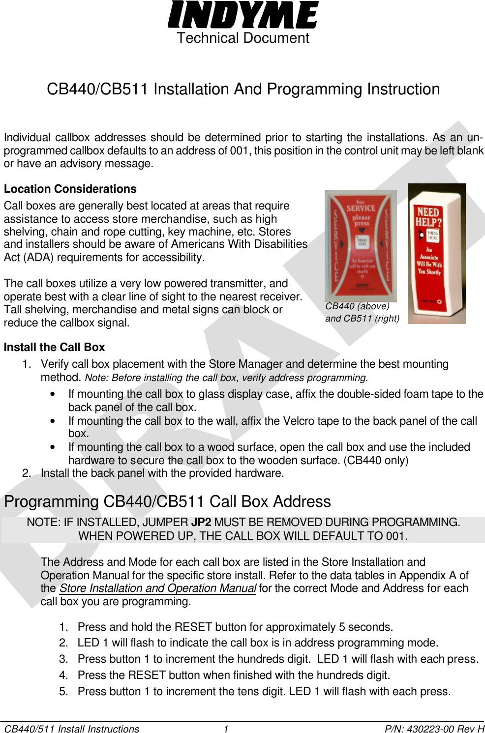
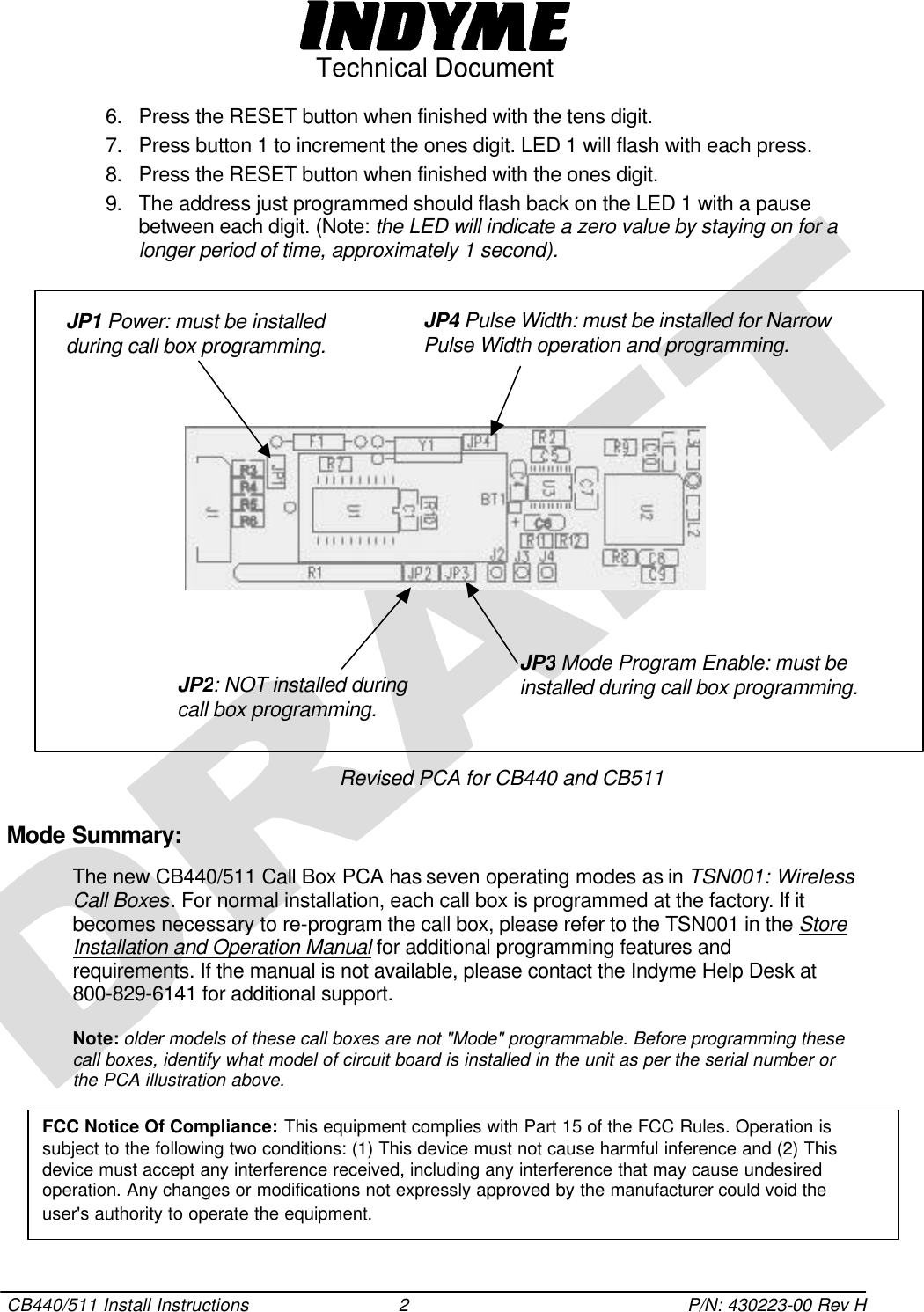
CB440 and CB511 Install and Programming Info

 Technical Document  CB440/511 Install Instructions 1 P/N: 430223-00 Rev H  CB440/CB511 Installation And Programming Instruction   Individual callbox addresses should be determined prior to starting the installations. As an un-programmed callbox defaults to an address of 001, this position in the control unit may be left blank or have an advisory message.  Location Considerations Call boxes are generally best located at areas that require assistance to access store merchandise, such as high shelving, chain and rope cutting, key machine, etc. Stores  and installers should be aware of Americans With Disabilities Act (ADA) requirements for accessibility.  The call boxes utilize a very low powered transmitter, and operate best with a clear line of sight to the nearest receiver. Tall shelving, merchandise and metal signs can block or reduce the callbox signal.  Install the Call Box 1. Verify call box placement with the Store Manager and determine the best mounting method. Note: Before installing the call box, verify address programming.  • If mounting the call box to glass display case, affix the double-sided foam tape to the back panel of the call box.  • If mounting the call box to the wall, affix the Velcro tape to the back panel of the call box. • If mounting the call box to a wood surface, open the call box and use the included hardware to secure the call box to the wooden surface. (CB440 only) 2. Install the back panel with the provided hardware.  Programming CB440/CB511 Call Box Address NOTE: IF INSTALLED, JUMPER JP2 MUST BE REMOVED DURING PROGRAMMING. WHEN POWERED UP, THE CALL BOX WILL DEFAULT TO 001.  The Address and Mode for each call box are listed in the Store Installation and Operation Manual for the specific store install. Refer to the data tables in Appendix A of the Store Installation and Operation Manual for the correct Mode and Address for each call box you are programming.   1. Press and hold the RESET button for approximately 5 seconds.  2. LED 1 will flash to indicate the call box is in address programming mode.  3. Press button 1 to increment the hundreds digit.  LED 1 will flash with each press. 4. Press the RESET button when finished with the hundreds digit. 5. Press button 1 to increment the tens digit. LED 1 will flash with each press.   CB440 (above) and CB511 (right)
 Technical Document  CB440/511 Install Instructions 2 P/N: 430223-00 Rev H 6. Press the RESET button when finished with the tens digit. 7. Press button 1 to increment the ones digit. LED 1 will flash with each press. 8. Press the RESET button when finished with the ones digit. 9. The address just programmed should flash back on the LED 1 with a pause between each digit. (Note: the LED will indicate a zero value by staying on for a longer period of time, approximately 1 second).                  Revised PCA for CB440 and CB511 Mode Summary:  The new CB440/511 Call Box PCA has seven operating modes as in TSN001: Wireless Call Boxes. For normal installation, each call box is programmed at the factory. If it becomes necessary to re-program the call box, please refer to the TSN001 in the Store Installation and Operation Manual for additional programming features and requirements. If the manual is not available, please contact the Indyme Help Desk at 800-829-6141 for additional support. Note: older models of these call boxes are not "Mode" programmable. Before programming these call boxes, identify what model of circuit board is installed in the unit as per the serial number or the PCA illustration above.    JP1 Power: must be installed during call box programming. JP4 Pulse Width: must be installed for Narrow Pulse Width operation and programming. JP3 Mode Program Enable: must be installed during call box programming. JP2: NOT installed during call box programming. FCC Notice Of Compliance: This equipment complies with Part 15 of the FCC Rules. Operation is subject to the following two conditions: (1) This device must not cause harmful inference and (2) This device must accept any interference received, including any interference that may cause undesired operation. Any changes or modifications not expressly approved by the manufacturer could void the user's authority to operate the equipment.

Navigation menu