Indyme Solutions GENCLBX Call Box Transmitter User Manual 430223 01 Draft revB CB514
Indyme Solutions, Inc Call Box Transmitter 430223 01 Draft revB CB514
Contents
- 1. Installation Guide
- 2. CB440 and CB511 Install and Programming Info
- 3. CB514 Install and Programming Info
- 4. Users Manual
CB514 Install and Programming Info
Technical Document
CB514 Install Instructions 1 P/N: 430223-01 Rev B
CB514 Installation And Programming Instruction
Individual callbox addresses should be determined prior to starting the installations. As an un-
programmed callbox defaults to an address of 001, this position in the control unit may be left
blank or have an advisory message.
Location Considerations
Director call boxes are generally best located in high volume
areas that demand a way to request additional services quickly,
such as front registers or service counters. Stores and installers
should be aware of Americans With Disabilities Act (ADA)
requirements for accessibility.
The call boxes utilize a very low powered transmitter, and operate
best with a clear line of sight to the nearest receiver. Tall shelving,
merchandise and metal signs can block or reduce the callbox
signal.
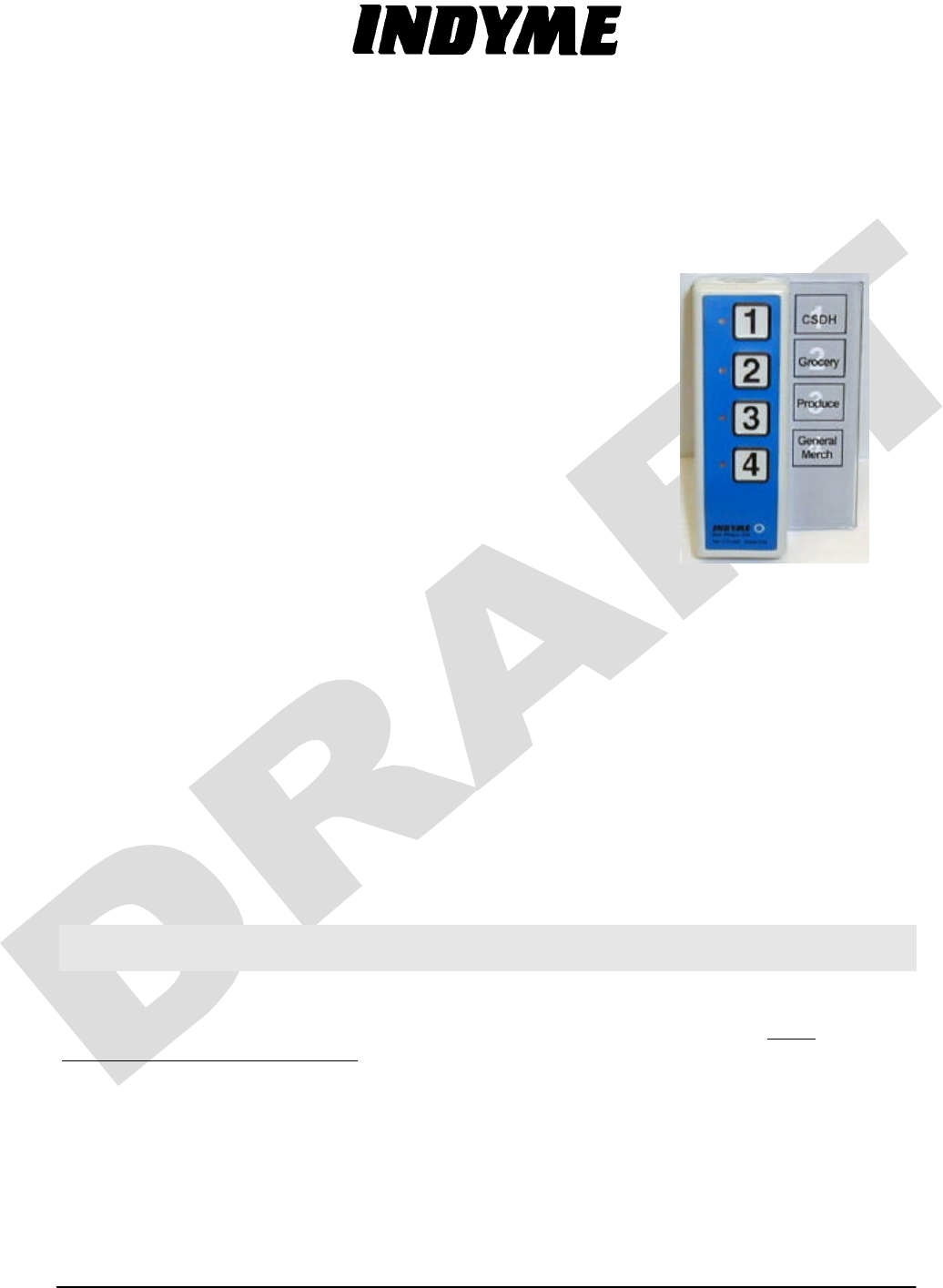
Install the CB514 Call Box
1. Verify call box and clear plastic label sleeve placement with the Store Manager. (The label
sleeve is optional and may not be used in all applications.)
2. Identify which side of the CB514 the label sleeve should be attached for the best visibility
and avoiding damage (the sleeve can be mounted on the left or right side of the call box).
3. Slide the label into the clear plastic sleeve (double-sided tape or Velcro will be installed on
the bottom of the label sleeve).
Programming the CB514 Call Box
To program the CB514, program the first button and the remaining three buttons are automatically
programmed with the next numerical values. When the call box "flashes" the newly programmed
address, the zero value will be indicated by a longer (slightly over a second) flash. For example: an
address of 001 would be shown as long flash (0), pause, long flash(0), pause, and a short flash (1).
NOTE: IF INSTALLED, JUMPER JP2 MUST BE REMOVED DURING PROGRAMMING.
WHEN POWERED UP, THE CALL BOX WILL DEFAULT TO 001.
The Address and Mode for each call box are listed in the Store Installation and Operation
Manual for the specific store install. Refer to the data tables in Appendix A of the Store
Installation and Operation Manual for the correct Mode and Address for each call box you are
programming.
1. Press and hold the RESET button for approximately 5 seconds.
2. LED 1 will flash to indicate the call box is in address programming mode.
3. Press button 1 to increment the hundreds digit. LED 1 will flash with each press.
4. Press the RESET button when finished with the hundreds digit.
Technical Document
CB514 Install Instructions 2 P/N: 430223-01 Rev B
5. Press button 1 to increment the tens digit. LED 1 will flash with each press.
6. Press the RESET button when finished with the tens digit.
7. Press button 1 to increment the ones digit. LED 1 will flash with each press.
8. Press the RESET button when finished with the ones digit.
9. The address just programmed should flash back on the LED 1 with a pause between
each digit. (Note: the LED will indicate a zero value by staying on for a longer period of time,
approximately 1 second).
Revised PCA for CB514
Mode Summary:
The new CB514 Call Box PCA has seven operating modes as defined in TSN001:
Wireless Call Boxes. For normal installation, each call box is programmed at the factory.
If it becomes necessary to re-program the call box, please refer to the TSN001 in the
Store Installation and Operation Manual for additional programming features and
requirements. If the manual is not available, please contact the Indyme Help Desk at
800-829-6141 for additional support.
Note: older models of these call boxes are not "Mode" programmable. Before programming these
call boxes, identify what model of circuit board is installed in the unit as per the serial number or
the PCA illustration above.
FCC Notice Of Compliance:
This equipment complies with Part 15 of the FCC Rules. Operation is
subject to the following two conditions: (1) This device must not cause harmful inference and (2) This
device must accept any interference received, including any interference that may cause undesired
operation. Any changes or modifications not expressly approved by the manufacturer could void the
user's authority to operate the equipment.
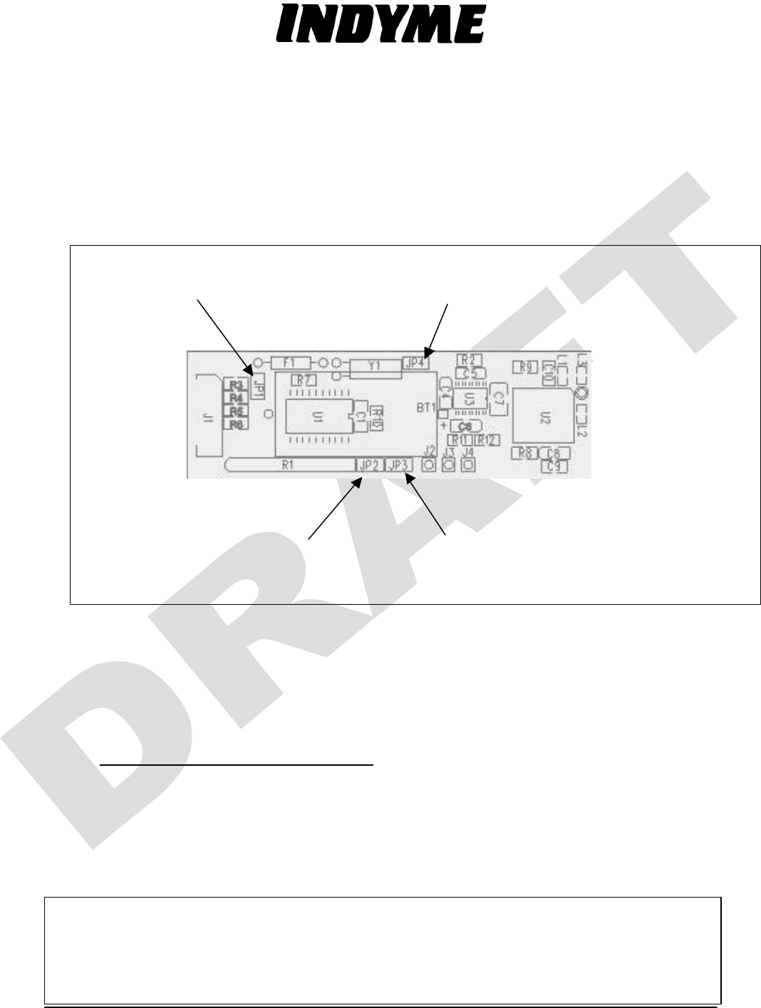
JP1
Power: mus
t be installed
during call box programming.
JP4
Pulse Width: must be installed for Narrow
Pulse Width operation and programming.
JP3
Mode Program Enable: must be
installed during call box programming.
JP2
: NOT installed during
call box programming.