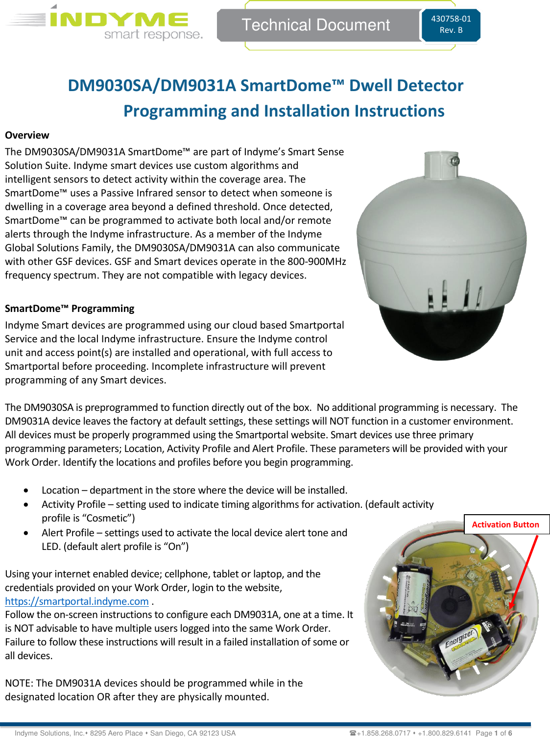
Indyme Solutions SD The Smart Dome uses a passive infrared motion sensor to detect the presence of people and send messages based on detection algorithms User Manual 1

Indyme Solutions, Inc The Smart Dome uses a passive infrared motion sensor to detect the presence of people and send messages based on detection algorithms Users Manual 1

Contents

Users Manual 1

   Technical Document 430758-01 Rev. B Indyme Solutions, Inc.⬧ 8295 Aero Place ⬧ San Diego, CA 92123 USA                                                         +1.858.268.0717 ⬧ +1.800.829.6141  Page 1 of 6 DM9030SA/DM9031A SmartDome™ Dwell Detector  Programming and Installation Instructions Overview The DM9030SA/DM9031A SmartDome™ are part of Indyme’s Smart Sense Solution Suite. Indyme smart devices use custom algorithms and intelligent sensors to detect activity within the coverage area. The SmartDome™ uses a Passive Infrared sensor to detect when someone is dwelling in a coverage area beyond a defined threshold. Once detected, SmartDome™ can be programmed to activate both local and/or remote alerts through the Indyme infrastructure. As a member of the Indyme Global Solutions Family, the DM9030SA/DM9031A can also communicate with other GSF devices. GSF and Smart devices operate in the 800-900MHz frequency spectrum. They are not compatible with legacy devices.  SmartDome™ Programming Indyme Smart devices are programmed using our cloud based Smartportal Service and the local Indyme infrastructure. Ensure the Indyme control unit and access point(s) are installed and operational, with full access to Smartportal before proceeding. Incomplete infrastructure will prevent programming of any Smart devices.  The DM9030SA is preprogrammed to function directly out of the box.  No additional programming is necessary.  The DM9031A device leaves the factory at default settings, these settings will NOT function in a customer environment. All devices must be properly programmed using the Smartportal website. Smart devices use three primary programming parameters; Location, Activity Profile and Alert Profile. These parameters will be provided with your Work Order. Identify the locations and profiles before you begin programming.   • Location – department in the store where the device will be installed. • Activity Profile – setting used to indicate timing algorithms for activation. (default activity profile is “Cosmetic”) • Alert Profile – settings used to activate the local device alert tone and LED. (default alert profile is “On”)  Using your internet enabled device; cellphone, tablet or laptop, and the credentials provided on your Work Order, login to the website, https://smartportal.indyme.com .  Follow the on-screen instructions to configure each DM9031A, one at a time. It is NOT advisable to have multiple users logged into the same Work Order. Failure to follow these instructions will result in a failed installation of some or all devices.   NOTE: The DM9031A devices should be programmed while in the designated location OR after they are physically mounted.   Activation Button
   Technical Document 430758-01 Rev. B Indyme Solutions, Inc.⬧ 8295 Aero Place ⬧ San Diego, CA 92123 USA                                                         +1.858.268.0717 ⬧ +1.800.829.6141  Page 2 of 6 1. On the Installer Registration screen, enter your name and contact information. This information will be used by Indyme Support personnel throughout the install and to ensure you are at the correct job site. 2. On the Work Order screen, verify the listed details match your present job site and, the list of devices match your inventory of products. Once all details are confirmed, select the “Start Work” button and begin your installation. 3. With the Devices screen showing, insert two size “C” Alkaline batteries into the DM9031A (should be included in the DM9031A box). The device will power up and produce a VERY LOUD “chime” tone and the LEDs will flash. The unit will associate with the local Indyme infrastructure, (access point and control unit), and its unique-id will appear highlighted in green on the webpage. Verify the unique-id that appears matches the sticker inside the DM9031A. 4. Select the highlighted device, (DM9031A).  In the Device Details screen, select the Location where the device will be installed.  The Activity Profile and Alert Profile will automatically be filled in.  Do not change these values. 5. Select the “Add Picture” button and take a picture of the device properly mounted.  6. Select the “Save” button. 6a.  (After the Save button), A “Sending Changes” pop up will appear. This will transfer the Device’s data to             the control unit. 6b.  The “Ready for Activation” pop up appears directing the user to press the button to activate changes. 6c.  Push the activation button as indicated.  When the transaction is complete, another pop up will appear – “Your changes have been saved.  Return to devices list?”.   Select Yes 6d.  Repeat until all DM9031A devices are properly programmed.  7. Once all devices have been programmed, return to the Work Order screen. Verify the number of Completed devices. Select the “Stop Work” button and close the work order. 8. Call Indyme to verify the devices are correctly configured and working.  NOTE: The DM9031A devices should be programmed while in the designated location OR after they are physically mounted.  SmartDome™ Installation The DM9030SA/DM9031A SmartDome™ are designed as ceiling mounted devices. They may be mounted directly to a drop-tile ceiling grid, extended from the grid using a telescoping pole or extended from a ceiling truss. Mounting hardware is available for all options. For ceiling heights of 11-feet or less, the should be direct mounted, heights of 12-feet or greater should use the telescoping pole.  Required Tools The following tools are recommended to complete the installation according to these instructions; (1) 1/4” or 1/2” socket wrench handle, (1) 9/16” socket, (1) 7/16” deep socket, (1) 3/16” Allen wrench, (1) pair pliers, (1) Philips screwdriver.
   Technical Document 430758-01 Rev. B Indyme Solutions, Inc.⬧ 8295 Aero Place ⬧ San Diego, CA 92123 USA                                                         +1.858.268.0717 ⬧ +1.800.829.6141  Page 3 of 6 DM9030SA/DM9031A SmartDome Mounting Direct Ceiling Mount 1. Identify all necessary mounting hardware. • (A) Dome Assembly • (B) Dome Mounting Plate  • (C) Grid Mounting Clip w/hardware                                      2. Attach the Grid Mounting Clip-(C), to the ceiling frame in the target area. Squeeze the clip to lock it in place. (Fig-1) 3. Attach the Dome Mounting Plate-(B), to the Grid Mounting Clip-(C), and secure in place with the washer and 7/16” nut.  Make sure groove in back of mounting plate (B) aligns with the ceiling grid. (Fig-2) 4. Attach the Dome Assembly-(A) to the Dome Mounting Plate -(B), gently turn clockwise to lock in-place. (Fig-3)         B C Fig-1 Fig-2 A Fig-3
   Technical Document 430758-01 Rev. B Indyme Solutions, Inc.⬧ 8295 Aero Place ⬧ San Diego, CA 92123 USA                                                         +1.858.268.0717 ⬧ +1.800.829.6141  Page 4 of 6 Telescoping Pole Mount 1. Identify additional necessary mounting hardware. • (D) Pole Pendant Cap & Conduit Connector (white) w/hardware  • (E) Telescoping Pole  •  (F) Elbow Joint • Items (A), (B), (C) above are required.           2. Place the Dome Mounting Plate (B) on top of the Pole Pendant Cap (D). Align the screw holes and secure in place with the provided screws. Screw the conduit connector to top of pole pendant cap. (Fig-5) 3. Attach the Dome assembly to the attached Pole Pendant and Dome Mounting Plate (B), press in and turn clockwise to lock in-place. (Fig-6)                     D E Fig-4 Fig-5 Fig-6 F E F
   Technical Document 430758-01 Rev. B Indyme Solutions, Inc.⬧ 8295 Aero Place ⬧ San Diego, CA 92123 USA                                                         +1.858.268.0717 ⬧ +1.800.829.6141  Page 5 of 6 4. The Telescoping Pole comes with a 4-1/4” bolt attached at the Elbow Joint. Disassemble the Elbow Joint and remove the bolt. (3/16” Allen Wrench, 7/16” Socket) (This bolt is ONLY used for mounting to an open ceiling truss.)  5. Attach the Grid Mounting Clip (C), to the ceiling in the target area. Squeeze the clip to lock it in place. (Fig-1) Attach the Elbow Joint (F) to the Grid Mounting Clip using the provided small washer and 7/16” nut. (Fig-7)        6. Re-attach the pole (E) to the Elbow Joint insuring the pole is straight up and down. Feed the Safety Cable around the ceiling tile frame and attach to opposite end of bolt. (Fig-8) 7. Loosen the pole collar (E) and extend to the desired length.  8. Attach the complete Dome Assembly to the end of the Telescoping Pole (E) using the machine screw. DO NOT align the screw with the hole in the side of the pole. Align the screw so it will tighten against the side of the pole. (Fig-9)                                     Fig-7 Fig-8 Fig-9
   Technical Document 430758-01 Rev. B Indyme Solutions, Inc.⬧ 8295 Aero Place ⬧ San Diego, CA 92123 USA                                                         +1.858.268.0717 ⬧ +1.800.829.6141  Page 6 of 6  FCC Notice of Compliance  FCC ID J69SD This device complies with Part 15 of the FCC Rules. Operation is subject to the following two conditions:  (1) this device may not cause harmful interference, and (2) this device must accept any interference received, including interference that may cause undesired operation.   Any changes or modifications not expressly approved by the party responsible for compliance could void the user’s authority to operate the equipment.  The antenna(s) used for this transmitter must be installed to provide a separation distance of at least 20 cm from all persons and must not be co-located or operating in conjunction with any other antenna or transmitter.  This equipment has been tested and found to comply with the limits for a Class B digital device, pursuant to part 15 of the FCC Rules. These limits are designed to provide reasonable protection against harmful interference in a residential installation. This equipment generates, uses, and can radiate radio frequency energy and, if not installed and used in accordance with the instructions, may cause harmful interference to radio communications. However, there is no guarantee that interference will not occur in a particular installation. If this equipment does cause harmful interference to radio or television reception, which can be determined by turning the equipment off and on, the user is encouraged to try to correct the interference by one or more of the following measures: • Reorient or relocate the receiving antenna. • Increase the separation between the equipment and receiver. • Connect the equipment into an outlet on a circuit different from that to which the receiver is connected. • Consult the dealer or an experienced radio/TV technician for help.   Industry Canada Notice of Compliance IC: 1809A-SD This device complies with Industry Canada license-exempt RSS standard(s). Operation is subject to the following two conditions: (1) this device may not cause interference, and (2) this device must accept any interference, including interference that may cause undesired operation of the device.  Any changes or modifications not expressly approved by the party responsible for compliance could void the user’s authority to operate the equipment.  Le présent appareil est conforme aux CNR d'Industrie Canada applicables aux appareils radioexempts de licence. L'exploitation est autorisée aux deux conditions suivantes : (1) l'appareil ne doit pas produire de brouillage, et (2) l'utilisateur de l'appareil doit accepter tout brouillage radioélectrique subi, même si le brouillage est susceptible d'en compromettre le fonctionnement.   Les changements ou modifications non approuvés expressément par la partie responsable de la conformité pourrait annuler l'autorité de l'utilisateur à faire fonctionner l'équipement.   Innovation, Science and Economic Development Canada ICES 003 Compliance Label: CAN ICES-3 (B)/NMB-3(B)

Navigation menu