Infinet Wireless R5000-L InfiNet Wireless 5.8 GHz Wireless Router User Manual InfiNet Wireless R5000 Quick Start Guide
Infinet Wireless Limited InfiNet Wireless 5.8 GHz Wireless Router InfiNet Wireless R5000 Quick Start Guide
Contents
- 1. Quick Start Manual
- 2. Users Manual
Quick Start Manual

Copyright © 2004-2006 by InfiNet Wireless Limited. 1
Updated: 24 April 2006
InfiNet Wireless Router
Quick start guide

Copyright © 2004-2006 by InfiNet Wireless Limited. 2
Copyright © 2004-2006 by InfiNet Wireless Limited.
All rights reserved.

InfiNet Wireless Router Quick start guide
Copyright © 2004-2006 by InfiNet Wireless Limited. i
Table of contents
FCC REGULATORY NOTICE....................................................................................................3
INDUSTRY CANADA REGULATORY NOTICE..........................................................................4
ANTENNA INSTALLATION AND OPERATION INFORMATION...............................................5
1. System Design..................................................................................................................5
2. Installation.......................................................................................................................5
3. Maximum Permissible Exposure..........................................................................................5
I. GETTING STARTED..........................................................................................................7
1. Scope of document...........................................................................................................7
Getting started..............................................................................................................7
Getting access to the router............................................................................................7
Point-to-point configuration.............................................................................................7
Point-to-multipoint configuration......................................................................................7
Performing outdoor testing.............................................................................................7
Connectors soldering schemes.........................................................................................7
2. Abbreviations...................................................................................................................7
3. Document marks..............................................................................................................8
4. Additional information.......................................................................................................8
II. GETTING ACCESS TO THE ROUTER.................................................................................9
1. PC/Laptop/LAN connection.................................................................................................9
Cabling (lab).................................................................................................................9
Accessing the router via Console....................................................................................10
Accessing the router via Ethernet...................................................................................12
2. Initial setup....................................................................................................................15
System parameters......................................................................................................15
Learning router’s capabilities.........................................................................................15
Radio module parameters configuration..........................................................................16
III. POINT-TO-POINT CONFIGURATION.............................................................................17
1. Routers configuration......................................................................................................17
2. Learning BS/CPE connection status...................................................................................19
Base Station table........................................................................................................19
CPE registration status..................................................................................................19
Checking radio connectivity...........................................................................................19
3. Providing PC/LAN connectivity..........................................................................................20
4. Link throughput test........................................................................................................22
IV. POINT-TO-MULTIPOINT CONFIGURATION..................................................................23
V. PERFORMING OUTDOOR TESTING...............................................................................24
1. Distance setting..............................................................................................................24
2. Learning link status/antenna alignment procedure..............................................................24

InfiNet Wireless Router Quick start guide
Copyright © 2004-2006 by InfiNet Wireless Limited. ii
VI. CONNECTORS SOLDERING SCHEMES...........................................................................27
1. Service cable connector soldering scheme.........................................................................27
2. Console cable connector for 5000-M and 5000-O soldering scheme......................................28

InfiNet Wireless Router Quick start guide
Copyright © 2004-2006 by InfiNet Wireless Limited. 3
FCC Regulatory Notice
A following FCC notice is applicable to models R5000-L, R5000-S and
R5000-O models working in 5.725 – 5.825 GHz band
Federal Communications Commission (FCC) statement
Note: This equipment has been tested and found to comply with the limits for a
Class A digital device, pursuant to Part 15 of the FCC Rules. These limits are
designed to provide reasonable protection against harmful interference when the
equipment is operated in a commercial environment. This equipment generates,
uses, and can radiate radio frequency energy and, if not installed and used in
accordance with the instruction manual, may cause harmful interference to radio
communications. Operation of this equipment in a residential area is likely to
cause harmful interference, in which case the user will be required to correct the
interference at his own expense.
Properly shielded and grounded cables and connectors must be used in order to
meet FCC emission limits. InfiNet is not responsible for any radio or television
interference caused by using other than recommended cables and connectors or
by unauthorized changes or modifications to this equipment. Unauthorized
changes or modifications could void the user's authority to operate the
equipment.
This device complies with Part 15 of the FCC rules. Operation is subject to the
following two conditions: (1) this device may not cause harmful interference, and
(2) this device must accept any interference received, including interference that
may cause undesired operation.

InfiNet Wireless Router Quick start guide
Copyright © 2004-2006 by InfiNet Wireless Limited. 4
Industry Canada Regulatory Notice
A following Industry Canada notice is applicable to models R5000-L,
R5000-S and R5000-O models working in 5.745 – 5.825 GHz band
Industry Canada compliance statement
This Class B digital apparatus meets all requirements of the Canadian
Interference-Causing Equipment Regulations.
This device complies with Industry Canada specification RSS-210. Operation is
subject to the following two conditions:
(1) this device may not cause interference, and
(2) this device must accept any interference received, including interference that
may cause undesired operation of the device.
Equipment (or its transmit antenna) that is installed outdoors is subject to
licensing.
The installer of this radio equipment must ensure that the antenna is located or
pointed such that it does not emit RF fields in excess of Health Canada limits for
the general population; consult Safety Code 6, obtainable from Health Canada’s
Web site: www.hc-sc.gc.ca/rpb.
Avis de conformité aux normes d’Industrie Canada
Cet appareil numérique de la classe B respecte toutes les exigences du
Réglement sur le matériel brouilleur du Canada.
Cet appareil est conforme а la spécification RSS-210 d'Industry Canada. Son
fonctionnement est soumis aux deux conditions suivantes:
(1) cet appareil ne peut engendrer aucune interférence et
(2) il doit accepter toute interférence qu'il reзoit, y compris celles qui peuvent
altérer son fonctionnement.
L'équipement (ou son antenne émettrice) est soumis а l'obtention d'une licence
s'il est installé а l'extérieur.
L'installateur de cet équipement radio doit veiller а ce que l'antenne soit
implantйe et dirigée de maniиre а n'émettre aucun champ HF dépassant les
limites fixées pour l'ensemble de la population par Santé Canada. Reportez-vous
au Code de sécurité 6 que vous pouvez consulter sur le site Web de Santé
Canada: www.hc-sc.gc.ca/rpb
InfiNet Wireless Router Quick start guide
Copyright © 2004-2006 by InfiNet Wireless Limited. 5
Antenna installation and operation information
1. System Design
Infinet Wireless, wireless routers, can be operated in both point to point and
Point to Multipoint modes, depending on equipment and system configuration.
System designers must be aware that changes to operating power levels and
antenna selection are required depending on the mode of operation of this
equipment.
Devices used exclusively for Point to Point operation are allowed to use antenna
gains greater than 6dBi without reduction of the RF power. Point to Multi-Point
operation requires the reduction of RF Power below 1Watt by the number of dB
above 6dBi antenna gain
15.247(c)(1)(iii): The operator of the spread spectrum or digitally modulated
intentional radiator or, if the equipment is professionally installed, the installer is
responsible for ensuring that the system is used exclusively for fixed, point-to-
point operations. The instruction manual furnished with the intentional radiator
shall contain language in the installation instructions informing the operator and
the installer of this responsibility
2. Installation
External antennas for InfiNet wireless equipment must be professionally
installed, due to the hazards involved in installation of equipments on towers,
building exteriors, and rooftops. A professional installer is one who is a properly
trained person whose normal job function includes this type of work. Generally
speaking a professional installer will have credentials from Narte, various
equipment suppliers, or another recognized body.
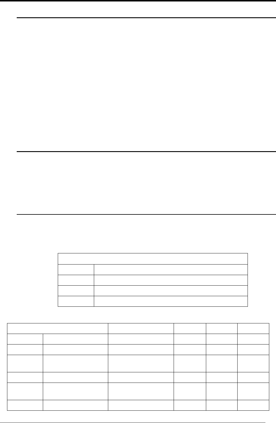
3. Maximum Permissible Exposure
This equipment this phone has been tested and meets the FCC RF exposure
guidelines when used with the antennas indicated in Table 2 below.
Worst-case distance for MPE for this product, for any of the antennas listed, is
the separation shown in Table 1.
Table 2 – Antennas certified for use with InfiNet Wireless routers
Antenna Types Notes R5000-O R5000-L R5000-S
Directional MT-486001 (MTI) 5.15-5.975 GHz 28dBi Yes Yes N/A
Directional SP1.5 (Radio Waves) 5.725 - 5.850 25.7 dBi Yes Yes N/A
Directional DA58 (Pacific
Wireless) 5,725 – 5,850 29 dBi Yes Yes N/A
Sector MT-484032/NV (MTI) 5.15-5.875 GHz 17dBi Yes N/A N/A
Sector MT-484033/NH (MTI) 5.15-5.875 GHz
16.5dBi Yes N/A N/A
Sector SEC-5V-60-18 (Radio 5.725 - 5.850 18 dBi Yes N/A
Table 1 – Maximum Permissible Exposure Data
Model Minimum Distance (worst case antenna)
R-5000-O 1.97 Meters (197 cm)
R-5000-L 1.58 Meters (158 cm)
R-5000-S 0.502 Meters (50.2 cm)

InfiNet Wireless Router Quick start guide
Copyright © 2004-2006 by InfiNet Wireless Limited. 6
Waves)
Sector SEC-5V-90-17
(Radio Waves) 5.725 - 5.850 17.0 dBi Yes N/A N/A
Sector TA-5705H-14-90 (Til
Tek) 5725-5875 16.5 dBi Yes N/A N/A
Sector SAH58-90 (Pacific
Wireless) 5725-5875 17.0 dBi Yes N/A N/A

InfiNet Wireless Router Quick start guide
Copyright © 2004-2006 by InfiNet Wireless Limited. 7
I. Getting Started
This document is designed to help engineers/technicians in rapid configuring of
InfiNet Wireless Routers. The document includes detailed instructions for first
configuration steps and configuration scenarios for typical network topologies.
1. Scope of document
This document consists of the following chapters:
Getting started
This chapter includes the information about this document purpose and structure.
Getting access to the router
The chapter describes how to get access to the router via Console Port and to
configure Ethernet port.
Point-to-point configuration
This chapter includes a comprehensive list of instructions for point-to-point link
configuration including providing LAN connectivity.
Point-to-multipoint configuration
The chapter briefly describes the difference between PTM and PTP topology
when building a network based on InfiNet Wireless Routers. Due to similarity of
PTM and PTP configuration it mostly references a previous chapter.
Performing outdoor testing
The chapter contains a list of requirements for outdoor testing. Also a basic steps
for link improvement and antenna alignment is presented.
Connectors soldering schemes
Contains connectors soldering schemes for Console cable and for ODU-IDU
service cable
2. Abbreviations
The following abbreviations are used in this document:
• BS – Base Station
• CPE – Customer Premises Equipment (also called subscriber or
subscriber unit)
• ODU – Outdoor Unit (relevant for 5000-O and 5000-M modifications)
• IDU – Indoor power supply Unit (relevant for 5000-O and 5000-M
modifications)
• RF cable – Radio Frequency cable to connect ODU and antenna/Router
and antenna for 5000-O and 5000-I modifications correspondingly
• LOS – Line-of-Sight
• STP cable – Shielded Twisted Pair cable to connect ODU and IDU
(relevant for 5000-O and 5000-M modifications)
• PTP – Point-to-Point topology
• PTM – Point-to-Multipoint topology

InfiNet Wireless Router Quick start guide
Copyright © 2004-2006 by InfiNet Wireless Limited. 8
• RMA – Routed Multiple Access Protocol
3. Document marks
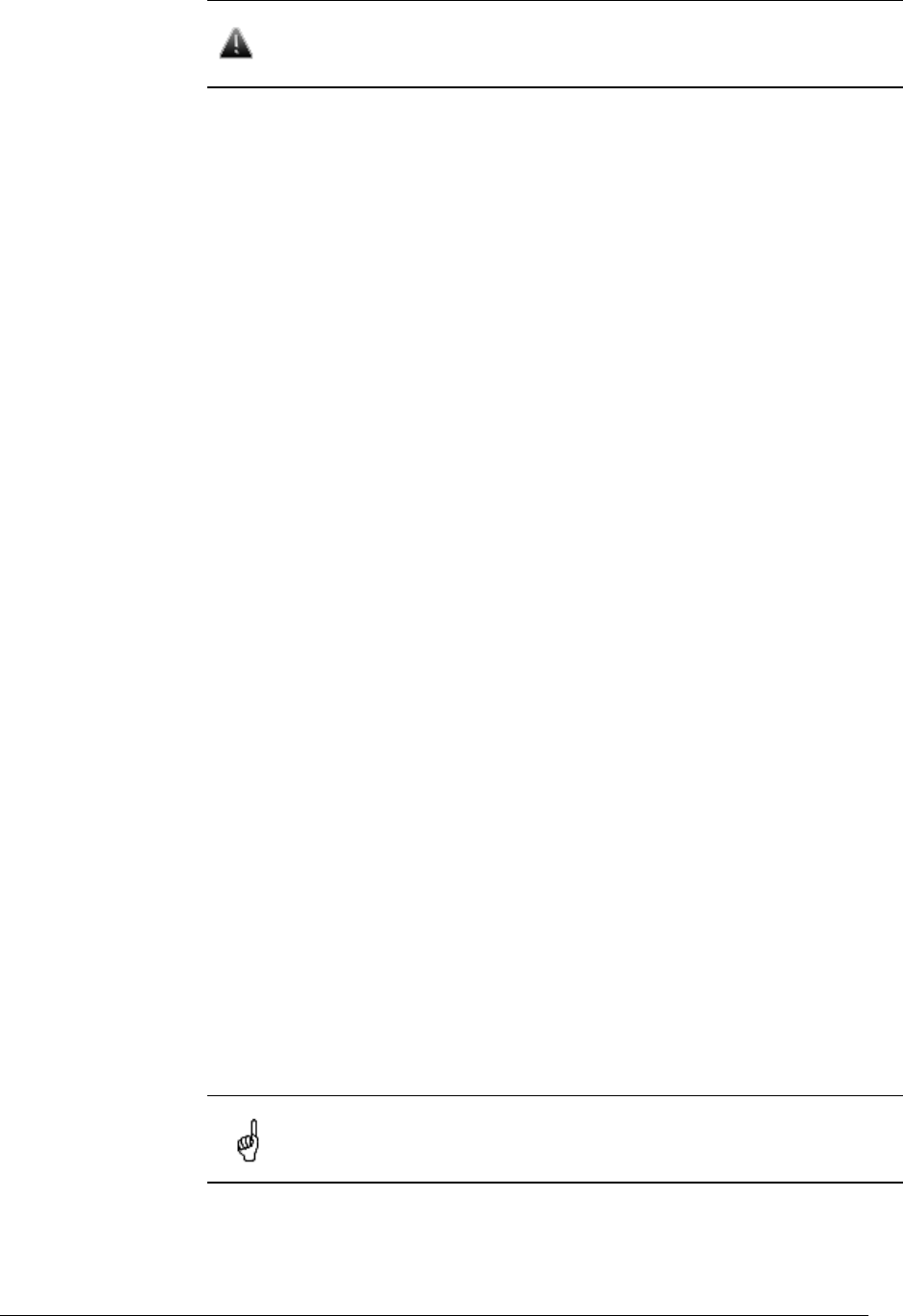
All warnings are marked with a special warning sign. One should pay
a great deal of attention to what is written in the Warning sections.
All notes are marked with a special note sign. Notes usually contain
useful comments or hints to the described section of the document.
4. Additional information
Additional information which is not included in this Manual can be found in the
following sources:
• Device passport located in the box with the device
• InfiNet Wireless Router. Technical User Manual
• WANFlex OS User Guide
• Our web-site: www.infinetwireless.com
InfiNet Wireless Router Quick start guide
Copyright © 2004-2006 by InfiNet Wireless Limited. 9
II.Getting access to the router
1. PC/Laptop/LAN connection
Cabling (lab)
The sequence of actions to be performed in order to connect the router to the
PC/Laptop is the following:
1. Unpack the equipment
2. If you do not have a service cable soldered, please do it using special
connectors included into the package according to the soldering scheme
located in the “Supplementary information” section. STP cable cat 5 or cat 5E
should be used.
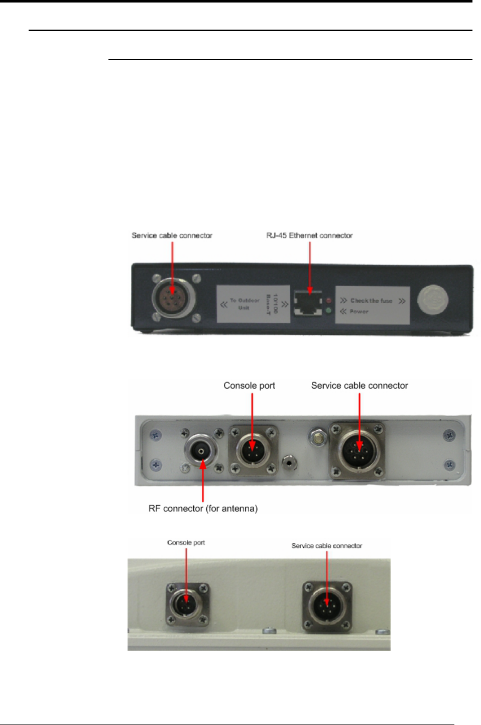
3. Locate IDU (blue case) and ODU (white case). Using STP Service cable
connect ODU and IDU. Service cable sockets are marked on the diagrams
below
Figure 1. IDU Front
Figure 2. 5000-O ODU Front
Figure 3. 5000-M ODU Front (fragment)
InfiNet Wireless Router Quick start guide
Copyright © 2004-2006 by InfiNet Wireless Limited. 10
Accessing the router via Console
If you cannot get access to the router using procedure described in “Accessing
the router via Ethernet” section please follow the steps described in this section.
1. Using InfiNet Console Cable please connect the router’s console port (see
Fig. 2) to the COM-port of your PC/Laptop
In order to accomplish the steps described in this section your
PC/Laptop must be equipped with a COM-port
2. Locate the power cord in the package
3. Plug the power cord into the IDU power supply connector and to the power
supply socket (110V 60 Hz)
4. Green power indicator on the IDU must light up
5. Power your PC/Laptop on
Following step’s screenshots are taken from Microsoft Windows XP.
You can also perform this procedure in Microsoft Windows
98/NT/2003
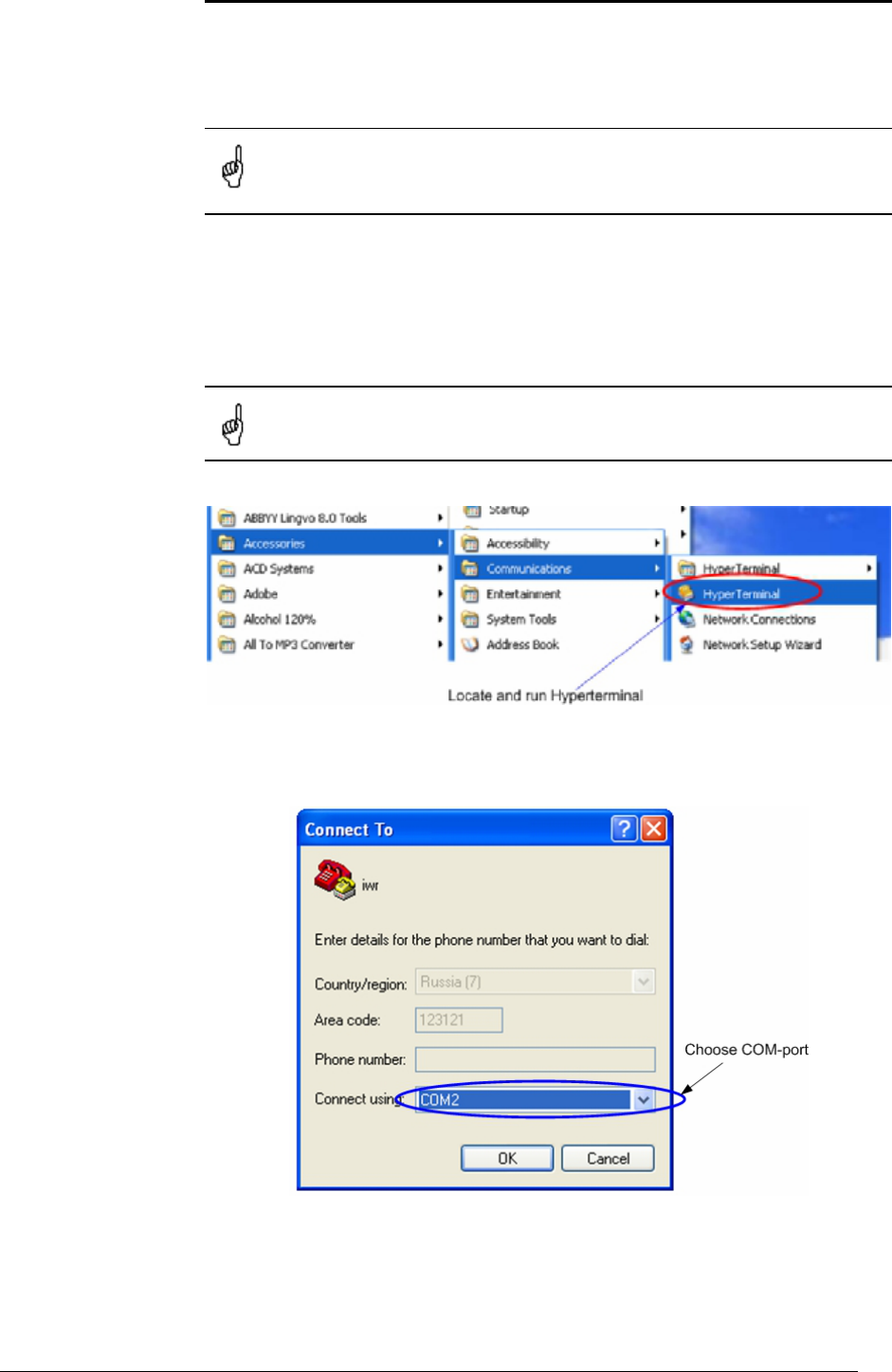
6. Run Hyperterminal. See Figure 4
Figure 4. Locate Hyperterminal
7. Indicate connection name (e.g. “IWR Lab Test”) and specify the COM-port
name to which the router is connected. See Figure 5
Figure 5. Select the port
InfiNet Wireless Router Quick start guide
Copyright © 2004-2006 by InfiNet Wireless Limited. 11
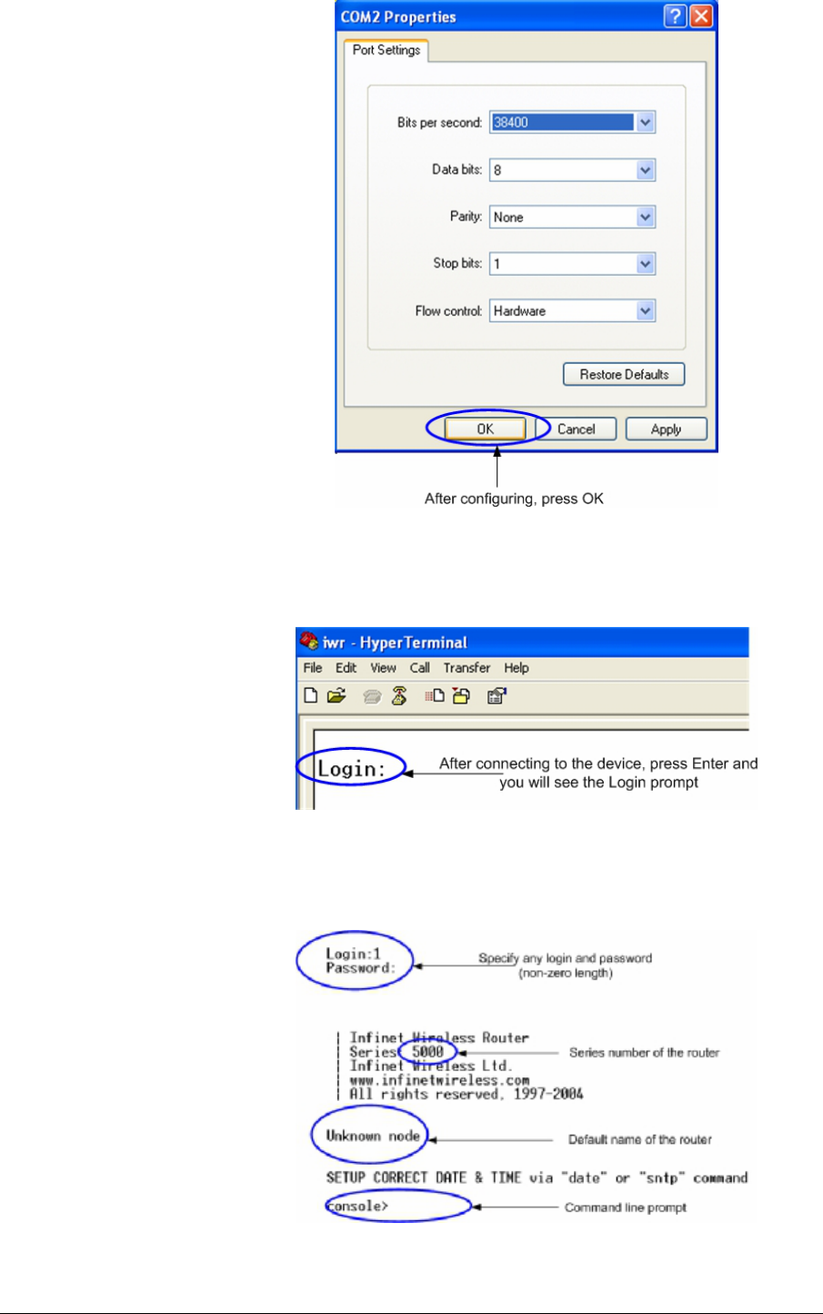
8. Specify port parameters exactly as shown on Figure 6
Figure 6. Port parameters
9. If you connected everything properly, selected the right port and made its
configuration right, after pressing enter on the white blank screen (after step
8) you should see WANFleX OS prompt as shown on Figure 7
Figure 7. WANFleX OS prompt
10. Your device has a factory configuration. That means that you can enter ANY
non-zero length login and password. Once this is done, you will see WANFleX
CLI (Command Line Interface). See Figure 8
Figure 8. “After login” screen
InfiNet Wireless Router Quick start guide
Copyright © 2004-2006 by InfiNet Wireless Limited. 12
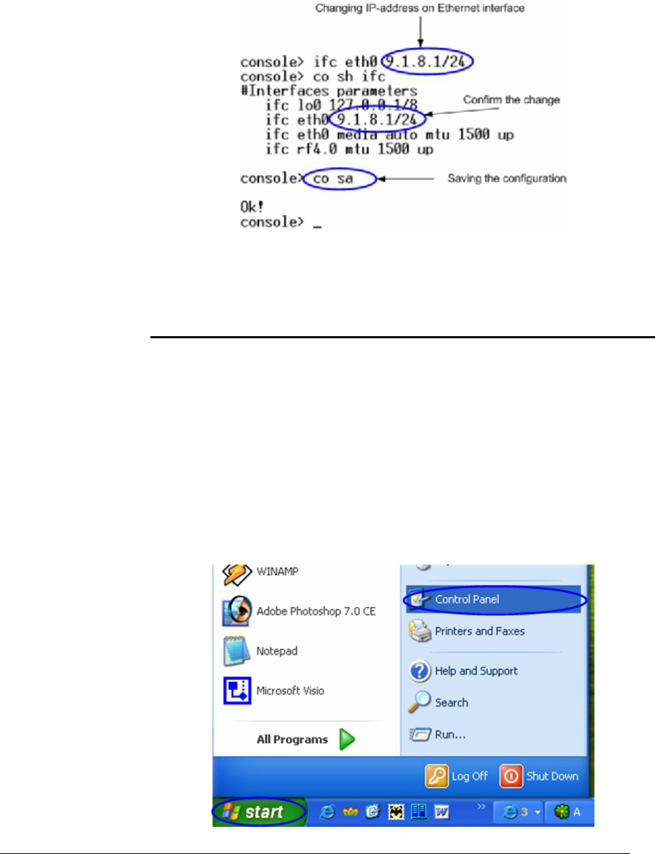
11. In order for your Router to be accessible from your LAN/PC/Laptop via
Ethernet, you should configure eth0 interface IP-address so the router
would allocate in the desired LAN (or accessible from your PC/Laptop
Ethernet adapter). Your can change this IP-address via “ifc eth0” command
as shown on figure 9. After changing the IP-address, save the configuration
using “co sa” command. In the example given the IP-address being
assigned to eth0 interface is 9.1.8.1 with mask length 24 (255.255.255.0).
In order to check whether your changes were correct, use “co sh ifc”
command which shows configuration for all interfaces of the router. Do not
forget to save your configuration using “co sa” (config save) command.
Figure 9. Changing IP-address on eth0 interface
12. If all your settings are correct you can connect the router to your LAN using
UTP cable with RJ-45 connectors (Ethernet port of the router is located on IDU).
Accessing the router via Ethernet
If your PC/Laptop does not have a COM-port or you want to plug the router to
the LAN switch you can configure it using Telnet protocol.
The default IP-address assigned to the eth0 interface of the router is
10.10.10.1 with 255.255.255.0 mask.
If you connect the router directly to the LAN/PC/Laptop you should either change
the IP-address on the Ethernet adaptor or create an alias IP-address which
would be located in 10.10.10.0/24 network.
Connect the router to LAN/PC/Laptop using UTP cable with RJ-45 connectors.
The procedure is the following:
1. Open the Control Panel in Windows. See Figure 10
InfiNet Wireless Router Quick start guide
Copyright © 2004-2006 by InfiNet Wireless Limited. 13
Figure 10. Open Control Panel
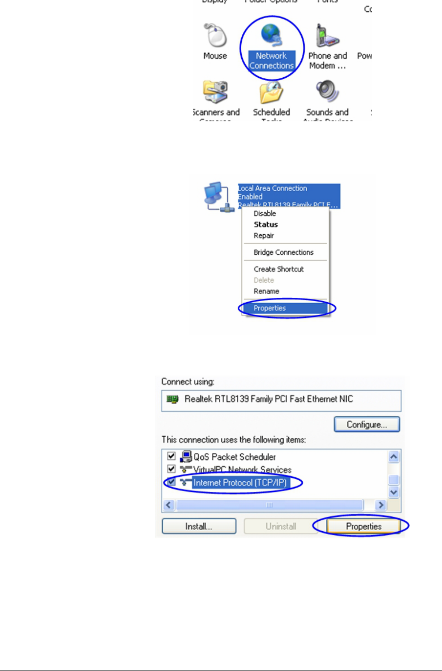
2. Open “Network connections” icon. See Figure 11
Figure 11. “Network connections”
3. In “Network connections” folder right mouse button click on the LAN
connection and click “Properties”. See Figure 12
Figure 12. LAN Connection properties
4. Choose “Internet protocol (TCP/IP)” and click “Properties”. See Figure 13.
Figure 13. Internet Protocol Properties
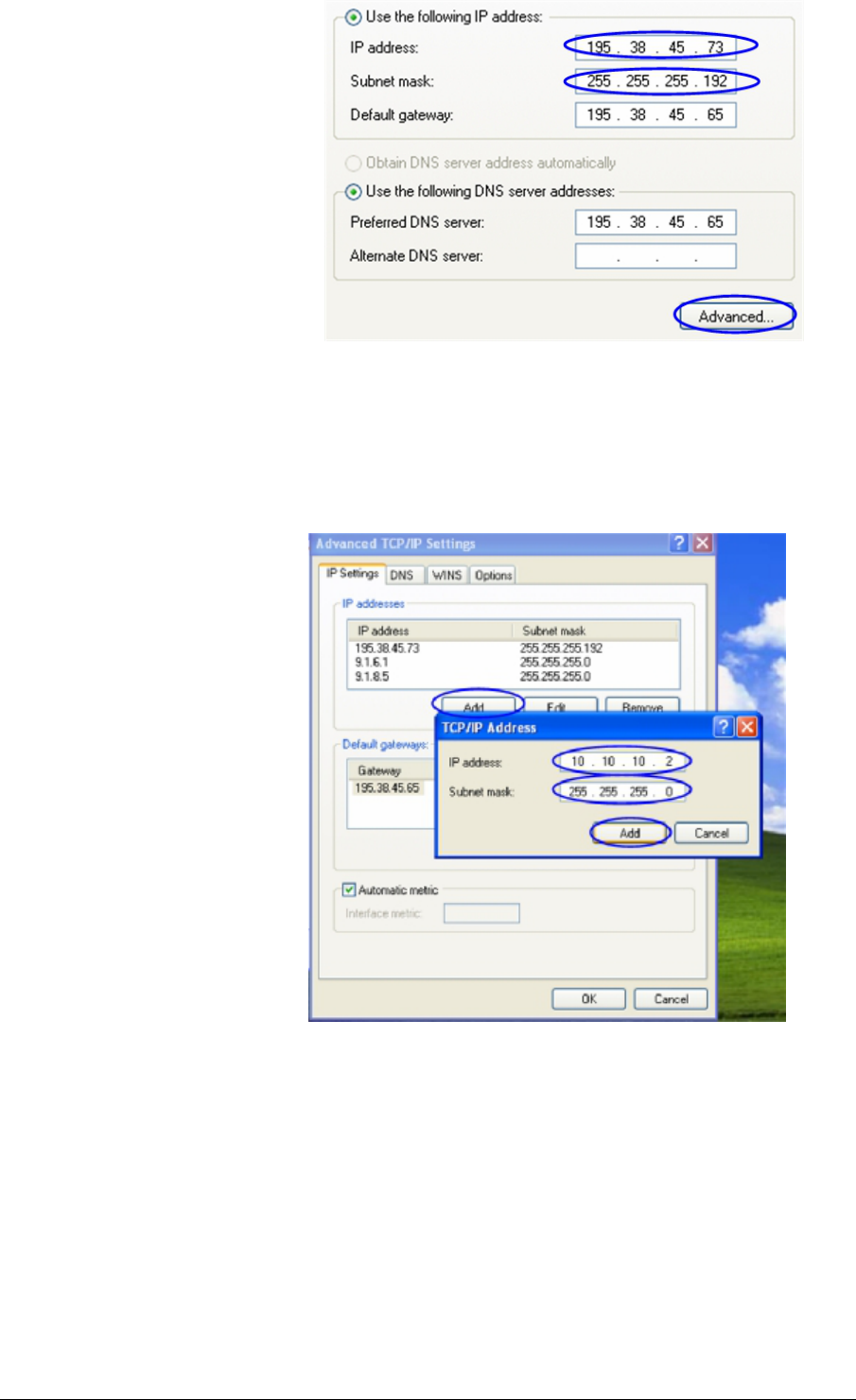
5. If you want to connect to the router using PC/Laptop you can just change an
IP-address on the Ethernet adaptor to some address from 10.10.10.0/24
network (e.g. change “IP-address” field to “10.10.10.2” and “Subnet mask”
to “255.255.255.0”). After that click OK and move to step 7. See Figure 14
InfiNet Wireless Router Quick start guide
Copyright © 2004-2006 by InfiNet Wireless Limited. 14
Figure 14. Change IP-address
6. If you are in a LAN and you do not want to change your primary IP-address
so you could keep LAN connectivity, you can assign an alias. In order to do
that, press “Advanced…” button (Figure 14). In “Advanced TCP/IP Settings”
click “Add” and put alias IP-address and mask (e.g. “10.10.10.2” and
“255.255.255.0” correspondingly). See Figure 15. Click OK in all windows
opened in the described procedure.
Figure 15. Create alias
7. Run “Telnet” utility using “Start->Run” and typing “telnet IP-address” where
IP-address is either the IP-address configured at Step 5 or alias configured
at Step 6.
8. Follow Steps 9 to 11 of “Accessing the router via Console” section in order to
change the IP-address on the eth0 interface on the router to the desired
one.
InfiNet Wireless Router Quick start guide
Copyright © 2004-2006 by InfiNet Wireless Limited. 15
2. Initial setup
Once you have got the access to the router via Telnet, you can perform initial
router setup. Run telnet application (Start->Run) using IP-address that was
assigned on the eth0 interface of the router (for example, 9.1.8.1)
First of all, let us list some useful commands that should be remembered.
• “help” – lists all available commands in the router
• “config show” (or “co sh” for short) – shows router’s current
configuration
• “config save” (or “co sa” for short) – saves router’s current
configuration
• “restart y” – immediate router reboot. Reboot lasts for 15 seconds
(approximately) and during this time you will not be able to control it
over Telnet
• “quit” – finishes current configuration session
The maximum number of concurrent Telnet sessions per one router is
five.
System parameters
Once you’ve got access to the router, the most common thing to be done in the
first turn is to set up some basic system parameters:
• System name. System name is specified by the following command:
system name [system_name]
• System user. This parameter will be used as a login:
system user [user_name]
• System password. System password is used as a password while login:
system password [password]
• System prompt. This command will change current command line
interface prompt:
system prompt [any_word]
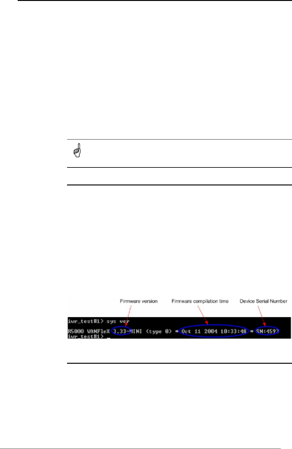
Also, it may be useful to know firmware version that is currently available in the
router and router’s serial number. “Sys ver” command can be used for this
purpose (Figure 16):
Figure 16. System version
Learning router’s capabilities
1. In order to learn current interfaces configuration, execute “co sh ifc”
command
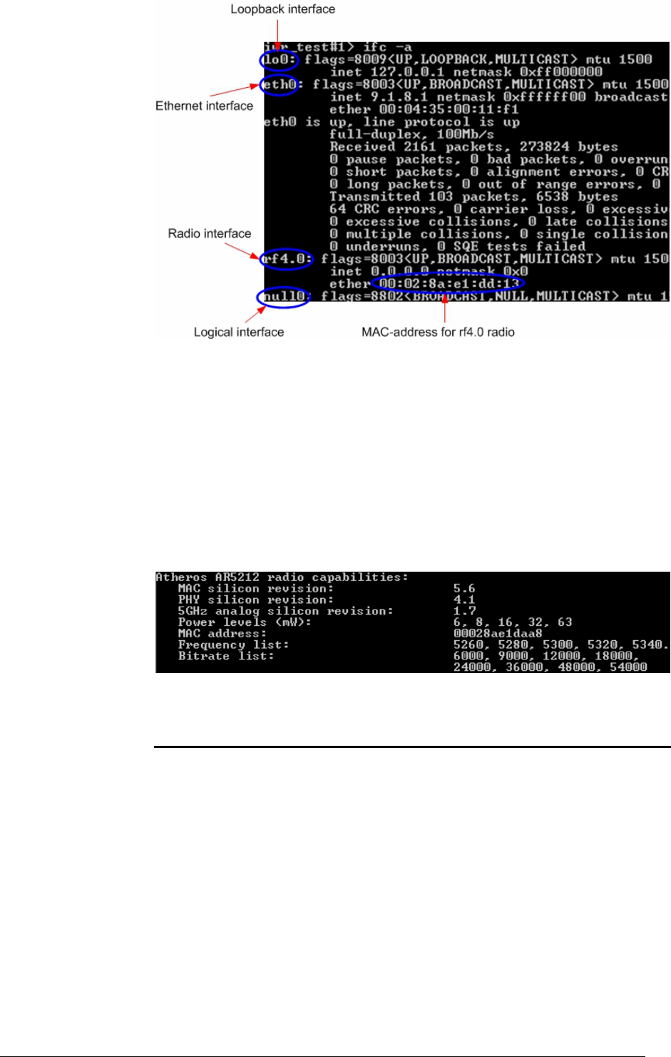
2. In order to learn all configured interfaces, their states and statistics, execute
“ifc –a” command. See Figure 17.
InfiNet Wireless Router Quick start guide
Copyright © 2004-2006 by InfiNet Wireless Limited. 16
Figure 17. Interfaces information
Note that radio interface name may differ from “rf4.0” depending on the
model’s frequency range (2.4GHz or 5GHz) and number of radio modules in
the device (one or two). Anyway, radio interface name always starts with
“rf”.
Information on the specific interface can be obtained using “ifc <IF-
NAME>” command. For example, “ifc rf4.0” will give you information on
“rf4.0” interface.
3. In order to get router’s capabilities including available frequency list, transmit
power levels, bitrates for the specific radio interface, “rf <IF-NAME> cap”
command is used. For example, “rf rf4.0 cap”. See Figure 18.
Figure 18. Router’s capabilities
Radio module parameters configuration
1. Power level changing is accomplished using “rf <IF-NAME> pwr <power-
level>” command. For example, “rf rf4.0 pwr 32” sets transmitting power
level to 32 mW. Power level specified in the command should be the one
from the list of available power levels.
2. Frequency changing is accomplished using “rf <IF-NAME> freq
<frequency>” command. For example, “rf rf4.0 freq 5340” sets current
working frequency to 5340 MHz. At the same time one radio module can
work only on ONE frequency.
3. Bitrate can be changed using “rf rf4.0 bitr <bitrate>” command. For
example, “rf rf4.0 bitr 24000” sets current bitrate to 24 Mbps.
InfiNet Wireless Router Quick start guide
Copyright © 2004-2006 by InfiNet Wireless Limited. 17
III.Point-to-Point configuration
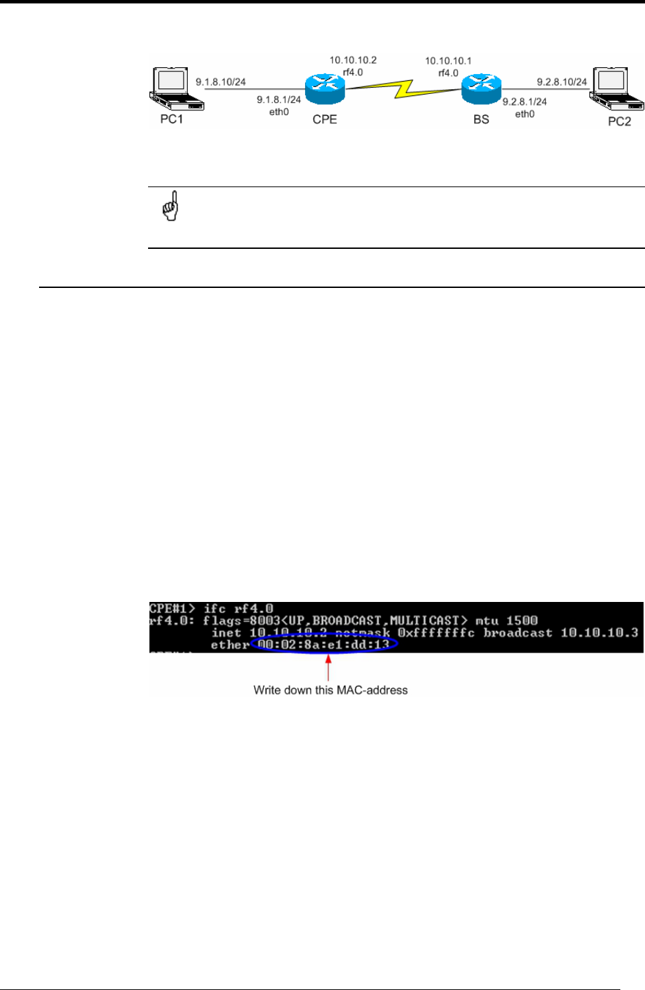
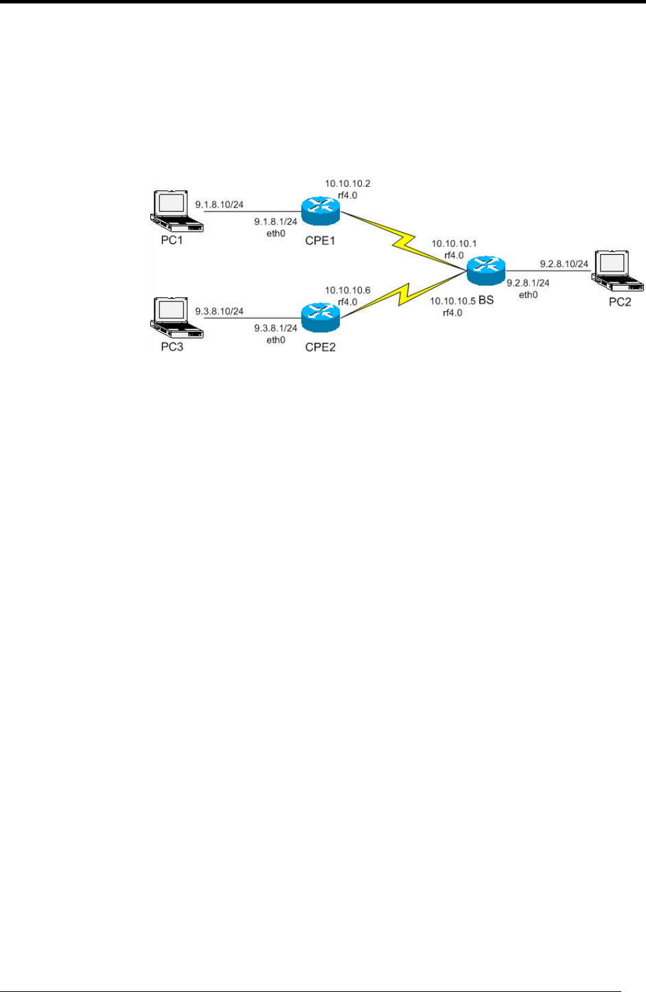
In our point-to-point configuration example we will built a simple network as
shown in Figure 19.
Figure 19. Sample network (PtP connection)
Here we will set up a connection between two PC/Laptops.
All configuration samples and notes will use IP-addresses and names
as specified in Figure 19.
1. Routers configuration
1. Choose one of the routers to be CPE and the other one to be BS.
2. Provide connectivity from PC1 to CPE and PC2 to BS following the procedure
described in “Getting access to the router”. As a result you should make sure
that you can ping/telnet CPE from PC1 and ping/telnet from PC2
3. Now we will proceed to routers configuration. From PC1 enter CPE router
using Telnet (Start->Run: “telnet 9.1.8.1”) and from PC2 enter BS router
(“telnet 9.2.8.1”)
4. On BS: configure desired frequency (e.g. “rf rf4.0 freq 5300”). Configure
SID (system identifier) - system identifier of the router, a hexadecimal number in
the range of 1H to FFFFFFH. All routers that are supposed to see each other on
the same radio link must have the same identifier – for example:
rf rf4.0 sid 20202020
5. On CPE: obtain its MAC-address for radio interface. In order to do that type:
“ifc <IF-NAME>”. IF-NAME – name of the radio interface. For example,
“ifc rf4.0”. See Figure 20.
Figure 20. Obtaining CPE MAC-address
6. On BS: using rma command configure the CPE. The command looks as
follows:
rma ab <IF-NAME> <MAC> ip=<IP> name=<NAME>
• IF-NAME – name of the radio interface (e.g. rf4.0)
• MAC – MAC-address of the configured CPE (see step 5)
• ip – IP-address for the radio interface with THIS CPE as viewed from the
Base Station. For example, you set up 10.10.10.1 IP-address for the
CPE. Once CPE is registered at the Base Station, the BS will
automatically assign IP-address to CPE radio interface with the BS. In
our example, it will be 10.10.10.2 address – a connection of BS with
EACH CPE is described as a sub-network with mask length 30 – that
means that 10.10.10.3 would become a broadcast address.
InfiNet Wireless Router Quick start guide
Copyright © 2004-2006 by InfiNet Wireless Limited. 18
• NAME – CPE’s mnemonic name.
In our sample network this configuration string will look as follows:
rma ab rf4.0 00028ae1dd13 ip=10.10.10.1 name=CPE
VERY IMPORTANT! ETHERNET IP-ADDRESS AND IP-ADDRESS FOR
RADIO INTERFACE MUST BE IN DIFFERENT NETWORKS
This warning is very important. That means that if you have 10.10.10.1/24
address on the Ethernet interface you cannot have any of 10.10.10.0/24
addresses on your radio interface.
7. On BS: type “rma start”. This will run Routed Multiple Access Protocol. From
this moment BS will wait for the configured CPEs (in our case it’s only one CPE)
for the registration request.
8. On CPE: we need to configure our BS for this CPE. “rma bs” command is
used for this purpose. Generally, each CPE can be configured for several BS. But
in our example we have only one BS to establish a PTP link. The syntax for BS
configuring is the following:
rma bs <IF-NAME> SID/[MINSPEED/]SPEED <FREQ-LIST>
• <IF-NAME> - radio interface name (e.g. rf4.0)
• SID – System identifier of the BS you want to connect to. In our case it
will be 20202020 (see step 4)
• MINSPEED – if autobitrate mechanism is used (see below) this value
will set the minimal value for the bitrate. This parameter is optional. If
skipped, the lowest available bitrate will be used
• SPEED – BS requested connection speed. This speed should not be
higher than maximal available bitrate for the CPE (see capabilities of the
router). If auotbitrate is not set, BS will work with CPE on this speed.
If autobitrate is set, BS will transmit on the highest reachable (and
available) bitrate and CPE will transmit on highest reachable speed but
not higher than SPEED value
• FREQ-LIST – list of frequencies on which the BS should be searched. It
can be one or several frequencies.
In our example the most evident thing that we must write is:
rma rf4.0 20202020/24000 5300
9. On CPE: type “rma start”. This will start Routed Multiple Access Protocol for
the CPE and it will immediately start “searching” for the configured BS by
sending registration requests.
10. On BS: turn on polling mode on. Polling mode (Wireless Marker Access) is
STRONGLY RECOMMENDED to be used in ALL cases as well as RMA protocol.
In order to turn polling on, please type:
rma <IF-NAME> poll
In our case, rma rf4.0 poll
Polling mode is turned on ONLY for the Base Station. This will include
ALL Base Station’s CPEs into the polling circleйо!
12. Do not forget to save the configuration using “co sa” command on both CPE
and BS
InfiNet Wireless Router Quick start guide
Copyright © 2004-2006 by InfiNet Wireless Limited. 19
2. Learning BS/CPE connection status
Once all configuration steps are correctly performed you should make sure that
the connection is established.
Actually, it makes no sense to connect antennas to the devices while lab testing
but still you need to make them “hear” each other. In order to do that, locate
their RF connector as close to each other as possible. Also you may try inserting
some kind of steel paper-clip in the connector – this might help in signal
improvement.
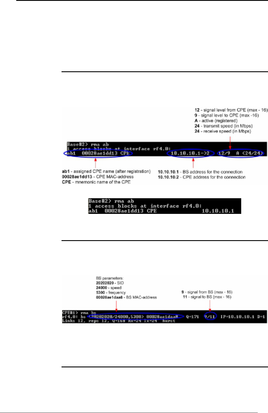
Base Station table
Base Station has a table of all configured CPEs no matter whether they are
registered or not. In our case, the table looks as shown on Figure 21 if CPE is
registered and as shown on Figure 22 if CPE is not registered. The command to
view BS table is “rma ab”.
Figure 21. BS table with registered CPE
Figure 22. BS table with not-registered CPE
CPE registration status
In order to know whether CPE is registered at the BS, one should type “rma bs”.
If CPE is not registered at the BS, the command will not output anything,
otherwise it will show BS information at which the CPE is registered. See Figure
23.
Figure 23. CPE registration status
If CPE is not registered on the BS, the command “rma bs” will have an empty
output.
Checking radio connectivity
As soon as you see corresponding records at CPE side (rma bs command)
confirming BS registration, and CPE is in BS’s table (rma ab command), you can
check their connectivity also using ping command.
1. Pinging from BS to CPE via radio
InfiNet Wireless Router Quick start guide
Copyright © 2004-2006 by InfiNet Wireless Limited. 20
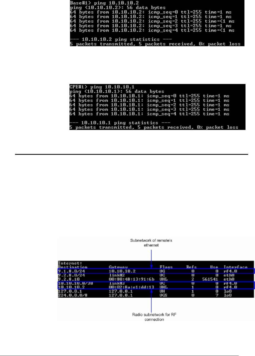
When CPE registers at the BS it is automatically assigned an IP-address next
to that from the BS side. In our case BS has 10.10.10.1 IP-address for RF
interface with the CPE and CPE in its turn has 10.10.10.2 for the RF
connection. See Figure 21: it says “10.10.10.1->2”. Figure 24 shows ping
result from BS to CPE.
Figure 24. Ping from BS to CPE
2. Pinging from CPE to BS via radio
The idea stays the same. From CPE we should use BS’s IP-address for the RF
connection. See Figure 25.
Figure 25. Ping from CPE to BS
3. Providing PC/LAN connectivity
Once radios “see” each other we need to make our LAN/PC/Laptop “see” each
other also. The best thing that should be done in the first turn is to turn on
dynamic routing on both of the devices. InfiNet Wireless Router supports two
types of routing: static routing (using route add command) and dynamic
routing using RIP v1 and v2 (command rip – Routing Information Protocol).
In order to turn RIP on, on both BS and CPE, type: rip start. This will start
dynamic routing and will force the routers with RIP turned on to exchange their
routing tables with each other. The exchange is performed approximately every
30 seconds.
On the Figure 26 Routing tables are shown (use net –r command) to make sure
that RIP protocol has already exchanged the routing tables with the remote.
Figure 26. Routing tables
InfiNet Wireless Router Quick start guide
Copyright © 2004-2006 by InfiNet Wireless Limited. 21
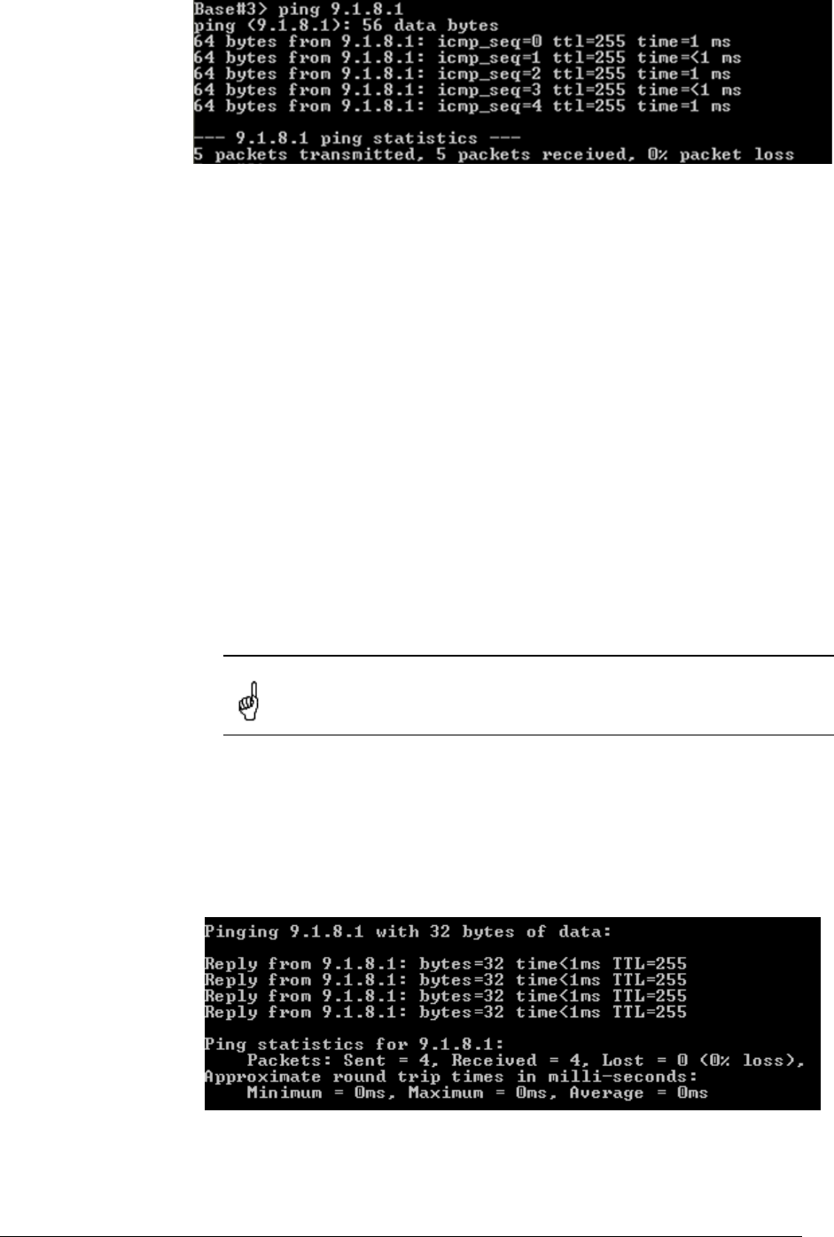
At this point, you can reach (e.g. ping) remote’s eth0 interface both from BS to
CPE and from CPE to BS. For example, from Base Station you can ping CPE’s
Ethernet interface (IP-address is 9.1.8.1). See Figure 27.
Figure 27. Pinging remote’s Ethernet
The next step is to make you Laptops/PC/LAN “see” each other.
If you connect two PC/Laptops (with MS Windows installed) two options are
available in this case:
1. Write a route to the corresponding Ethernet network at the opposite side of
the link. In order to do this, go “Start->Run” and run “cmd” – Command
Line. At the BS computer you should write the following:
route add 9.1.8.0 mask 255.255.255.0 9.2.8.1
This means that when an IP-packet goes from the computer connected to
your BS device to the computer at the CPE side, it will go to the BS Ethernet
interface. In the router, according to the routing tables formed using RIP
protocol, the packet will be sent via radio to the CPE router. After that, CPE
router will look up in its routing tables and send the packet through its
Ethernet interface to the remote computer.
At the CPE computer you should perform similar actions. Go “Start->Run”
and run “cmd” command. Type the following:
route add 9.2.8.0 mask 255.255.255.0 9.1.8.1
Now we provided connectivity between two computers.
All routes in Windows that are specified using route command have
power until next reboot of the computer.
2. The second option is to specify a default gateway for the PC/Laptop which
is going to be an Ethernet interface of the connected router. You can
specify default gateway parameter in the window shown on Figure 14.
Please refer. For the BS side it will be 9.2.8.1, for CPE – 9.1.8.1
In order to make sure that your PC/Laptops are connected, you can ping one
side from the other one. For example, from BS connected computer we are
pinging remote computer at the CPE side (Figure 28)
Figure 28. Pinging remote computer
Once attainability is obtained from both sides, you can try to carry out some
performance tests.
InfiNet Wireless Router Quick start guide
Copyright © 2004-2006 by InfiNet Wireless Limited. 22
4. Link throughput test
The most evident way to test link throughput is to install FTP server on either
first or second computer. For example, we set it up on the CPE computer.
During link throughput test using PC or Laptop with MS Windows please note the
following:
1. Hard disk drive speed or Ethernet adaptor speed may become a bottleneck
of the system at either side.
2. In MS Windows you need to run several (3 or more) TCP or UDP streams to
load up the radio link. In this case you will obtain a correct result.
Log on to FTP server on the remote computer. To do that go “Start->Run” and
execute “ftp 9.1.8.10”. IP-address 9.1.8.10 is the address of the remote
computer. Enter login and password for the FTP-server.
Run several FTP streams from the remote computer. In order to do that create
several FTP sessions according to the procedure described in the previous
paragraph and start downloading files from the remote computer (files should be
relatively big).
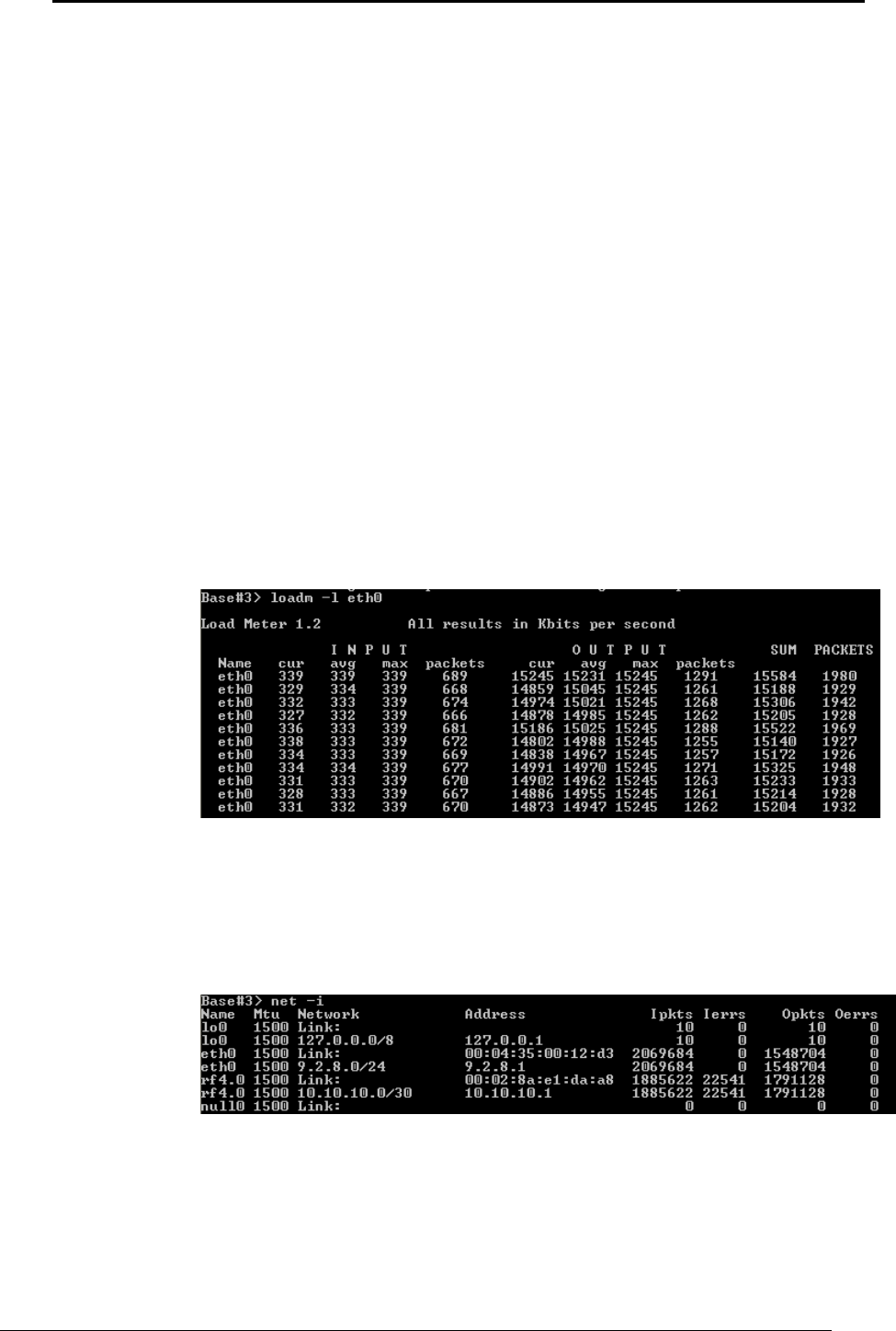
Once the streams are run you can check the throughput using Load Meter utility
built into the router. You can run it on either side. Run it for the eth0 interface.
The command is the following:
loadm –l eth0
“-l” parameter means line-by-line output.
The example is shown on the Figure 29.
Figure 29. Load meter utility
In the second column from the right you can see the total throughput in both
sides. In our example it is approximately 15.2 Mbps.
Also, you can review statistics using net –i command. It shows number of
successfully received/sent packets and faulted packets through each interface.
See Figure 30.
Figure 30. Network statistics
InfiNet Wireless Router Quick start guide
Copyright © 2004-2006 by InfiNet Wireless Limited. 23
IV.Point-to-Multipoint configuration
Generally, point-to-multipoint configuration is NO different from point-to-point
configuration in terms of devices configuration. This flexibility is obtained due to
common hardware/software platform used in InfiNet Wireless routers. Thus,
before reading this section of the Guide one MUST read carefully Point-to-Point
Configuration section in order to set up connection between the Base Station and
one CPE. In our next example we will add one MORE CPE to the network. If you
want to add more CPEs please follow the procedure described a desired number
of times.
Let us look at the Figure 31 that shows our network design.
Figure 31. PTM network design
Here we have added another CPE (CPE2) from a different network. No need to
have a detailed description of each step to be taken as all of them were
discussed in the previous chapter. The steps to be taken are the following:
1. Get access to the router (CPE2) from PC3.
2. Configure BS router’s CPE table for the CPE2. In order to do that learn CPE2
MAC-address for the radio (ifc -a command). On the BS execute the following
command: rma ab rf4.0 <MAC> ip=10.10.10.5 name=CPE2
<MAC> - is a MAC-address of CPE2 radio interface.
10.10.10.5 – IP-address of the BS connection with CPE2 from the side of
BS. CPE will be automatically assigned next IP-address for its connection
with BS after its registration.
3. Configure BS at the CPE side. It should be done in the same way as we did for
the first CPE: rma rf4.0 20202020/24000 5300
Requested speed (here 24000) may differ according to the CPE
capabilities and your network design.
4. Run RMA at the CPE: rma start
5. After some time (several seconds) the CPE will register at BS (if the
configuration was accomplished correctly). To learn that, type rma bs at the
CPE side (you will see BS parameters) and rma ab at the BS side (you will see
whether this CPE is registered or not).
6. Run RIP protocol on CPE (rip start)
7. Provide PC3 connectivity from all nodes of the network. Write corresponding
routes on all PCs. For PC1 and PC2 it will be a route to 9.3.8.0/24 network. On
PC3 it will be routes to 9.2.8.0/24 and 9.1.8.0/24 network. If you use eth0
address of the router as a default gateway for the PC you do not have to write
routes.
Note that BS throughput will be redistributed between CPEs according to
different criteria, including their connection speed with BS and QoS rules (if any).

InfiNet Wireless Router Quick start guide
Copyright © 2004-2006 by InfiNet Wireless Limited. 24
V. Performing outdoor testing
Before carrying out outdoor testing make sure that the equipment is properly
configured and tested in the lab. If you use outdoor equipment please prepare
service cables to connect IDU and ODU and check them in the lab. Also the
following accessories may be very useful while outdoor testing:
1. InfiNet Console cable to perform configuration of the rooftops/masts etc
2. Binoculars to locate the opposite side
3. Mobile phones at either side to coordinate each others actions
4. Screwdrivers set
5. Soldering iron in case if you have to fix some problems with connectors.
6. Voltage analyzer to reveal cable problems if any
When planning your outdoor testing it is strongly recommended to perform
calculations using:
• Speed/Range Calculator
• Fade Margin Calculator
Both of these calculators are located on InfiNet Wireless web-site
www.infinetwireless.com in the “Support” section.
How-to-use instructions are located in the Technical User Manual on the CD
delivered with the equipment.
1. Distance setting
For outdoor testing/deployment it is vitally important to set up distance
parameter correctly. The recommended procedure is the following:
1. If the you have a PTP topology, on the BS you set up the distance to the
CPE in kilometers. It is required to set up a bit bigger distance.
Setting up a smaller distance may cause errors on the link. At the
CPE set up distance as auto
2. In case of PTM topology on BS set up the distance to the remotest CPE. On
every CPE set up distance as auto
Distance parameter is set up using rf command:
rf rf4.0 distance <VALUE>
2. Learning link status/antenna alignment procedure
In order to install the equipment, please do the following:
1. Install ODU and antenna at the roof top/mast etc. Connect ODU and antenna
using RF cable. If the link is just for testing usage make sure that it is not
going to rain or snow (because in this case you do not have to seal the
connectors).
2. Even in test link it is highly recommended to provide all grounding. Ground
the ODU to the mast/building grounding contour
3. Usually when installing ODU at the top, the ODU-IDU service cable is already
connected to the ODU.
4. Connect ODU-IDU cable to IDU indoors
5. Provide IDU grounding to the LAN grounding contour
6. Connect power cable to IDU and plug this cable into the power socket
InfiNet Wireless Router Quick start guide
Copyright © 2004-2006 by InfiNet Wireless Limited. 25
Once the power is switched on, you can access the router via Telnet (all
necessary configuration steps were already taken in the lab).
It takes approximately 10-15 seconds for RMA to perform registration procedure.
After this period of time you can check the following:
• On BS: type “rma ab” to learn whether CPEs are registered
• On CPE: type “rma bs” to learn whether CPE has a BS registration
If it turns out that during some significant period of time (1 minute) there is no
CPE registration at BS, it can generally imply two options:
• Link fade margin is not sufficient to handle the connection
• Antenna alignment procedure is required in order to establish the connection
Even if registration has occurred but signal levels are not enough (signal levels
according to InfiNet scale are meant in the case, antenna alignment procedure is
strongly recommended.
In both cases (whether there is a registration or not) the following procedure for
antenna alignment is recommended:
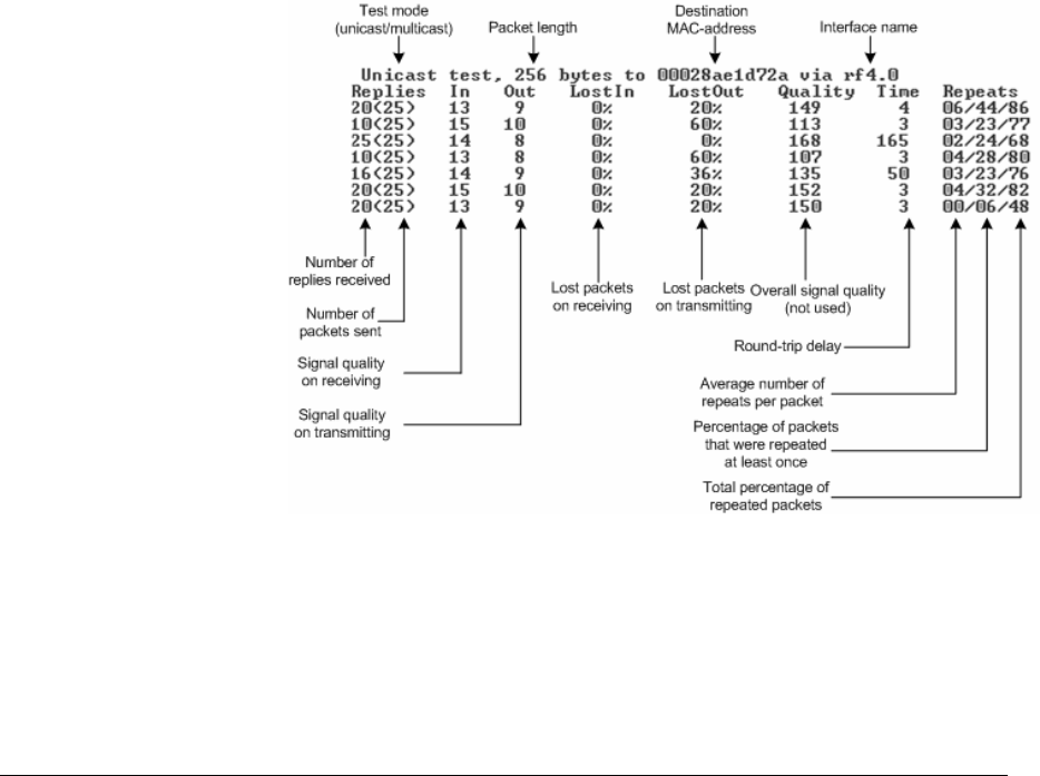
1. Either on BS device or CPE run rma test. Run it only from ONE side. The
command looks as follows:
rma rf4.0 test <MAC> 1400
Here, <MAC> - is a MAC-address of the CPE radio.
1400 – the length of the testing packet.
From CPE side it is possible to run rma test only if CPE has a registration on
BS.
2. Antenna alignment should be done only from one side at one time. Align one
side, than other side. Use mobile phones to check current signal levels. The
output of rma test command is demonstrated on the Figure 32.
Figure 32. Rma test output
3. The link can be claimed to be working when the following requirements are
met:
• Percentage of LostIn and LostOut packets is equal to 0
• Quality parameter is 120 and higher
• No repeats (00/00/00 value must be obtained)
InfiNet Wireless Router Quick start guide
Copyright © 2004-2006 by InfiNet Wireless Limited. 26
• Achievement of required signal levels (In and Out parameters).
Appropriate signal levels are from 4(5) to 10(11). Keep in mind that
the antenna alignment should be performed slowly and with pauses.
After each alignment step it is required to wait for at least 3 seconds
to see the alignment result in rma test table.
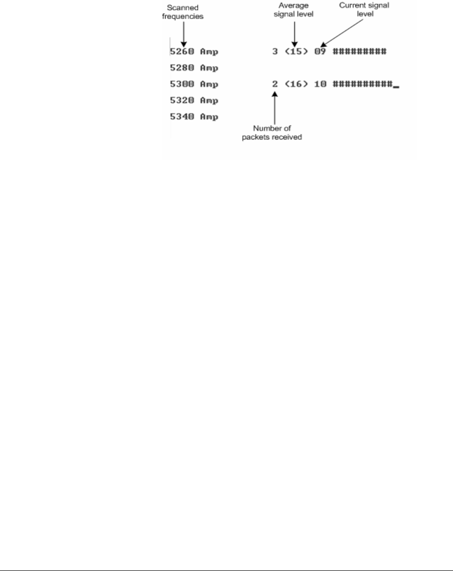
4. Interference can be a possible reason for the link quality degradation
(number of repeats increases, CPE does not register at the BS etc). Muffer
utility is used to monitor electromagnetic environment. In order to run
muffer one should turn RMA off using rma stop command. Review mode is
recommended to see the activity on all available for your radio frequencies:
muffer rf4.0 review
Figure 33 shows a sample output for this command.
Figure 33. Muffer review mode
On the figure we can see the activity on frequencies 5260 and 5300 MHz. If a
strong and permanent activity is located on the frequency that is used by your
link, it is strongly recommended to switch to another frequency which is free
from any activity.
5. If you fail to establish a link on a desired bitrate you can either change the
requested speed from CPE or turn on autobitrate mechanism. This mechanism
automatically varies the speed (from both sides) according to changing link
conditions. If the mechanism is turned on on CPE, the BS will also work with this
mechanism. If it is turned on on BS, the whole cell will switch to this mode. The
syntax for the command is the following:
rma rf4.0 autobitrate

InfiNet Wireless Router Quick start guide
Copyright © 2004-2006 by InfiNet Wireless Limited. 27
VI. Connectors soldering schemes
1. Service cable connector soldering scheme
InfiNet Wireless Router Quick start guide
Copyright © 2004-2006 by InfiNet Wireless Limited. 28
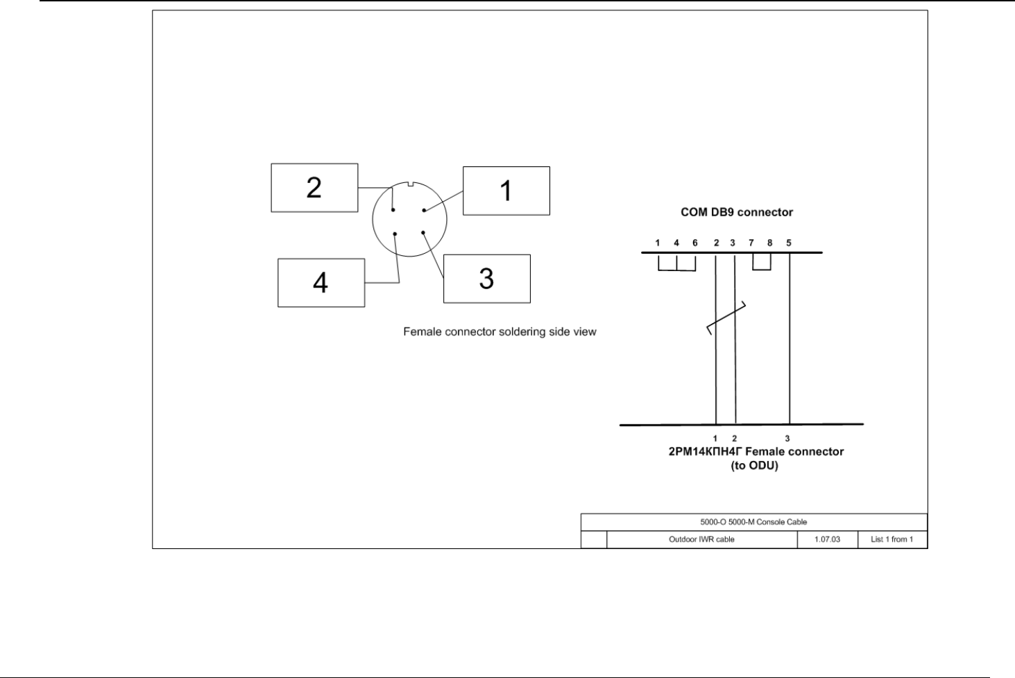
2. Console cable connector for 5000-M and 5000-O soldering scheme