Infinet Wireless R5000-L InfiNet Wireless 5.8 GHz Wireless Router User Manual InfiNet Wireless R5000 Quick Start Guide
Infinet Wireless Limited InfiNet Wireless 5.8 GHz Wireless Router InfiNet Wireless R5000 Quick Start Guide
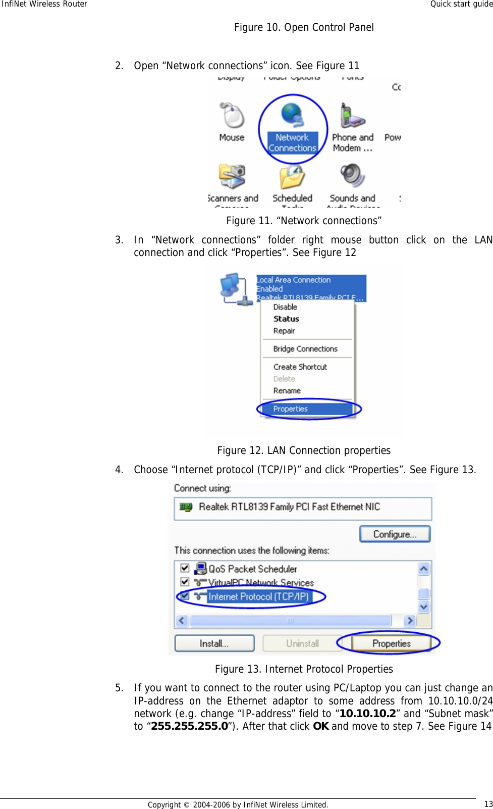
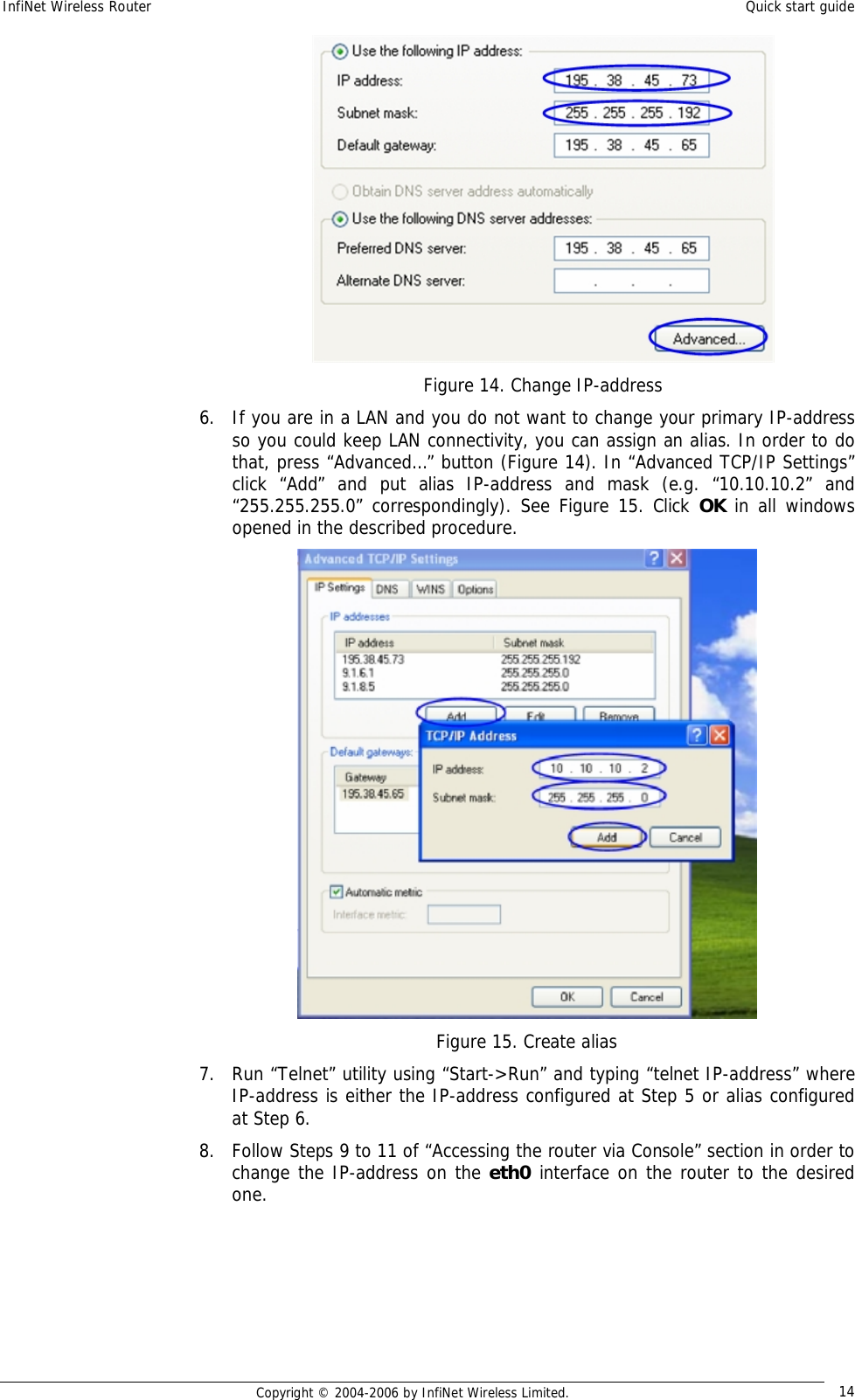
Contents
- 1. Quick Start Manual
- 2. Users Manual
Quick Start Manual
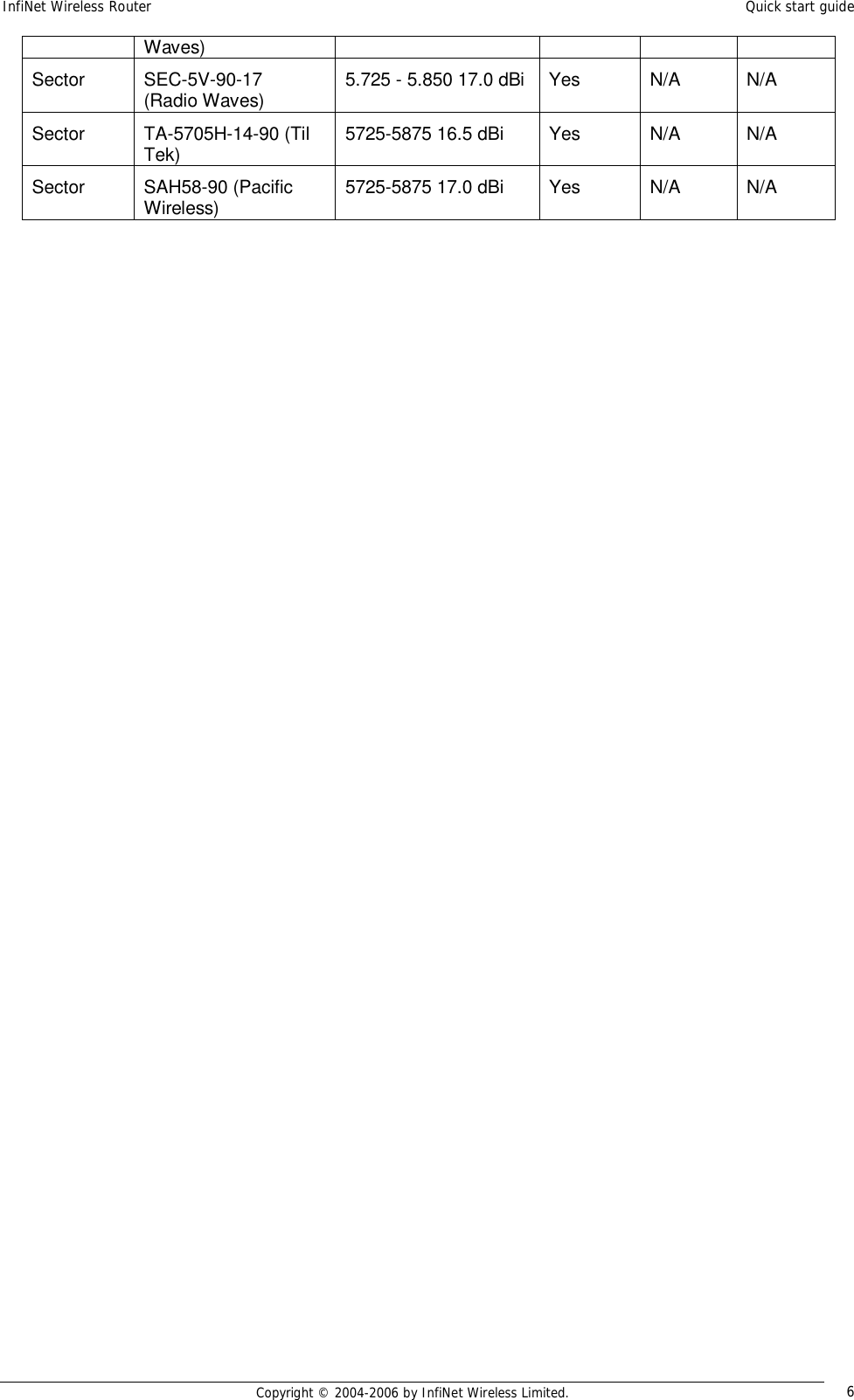
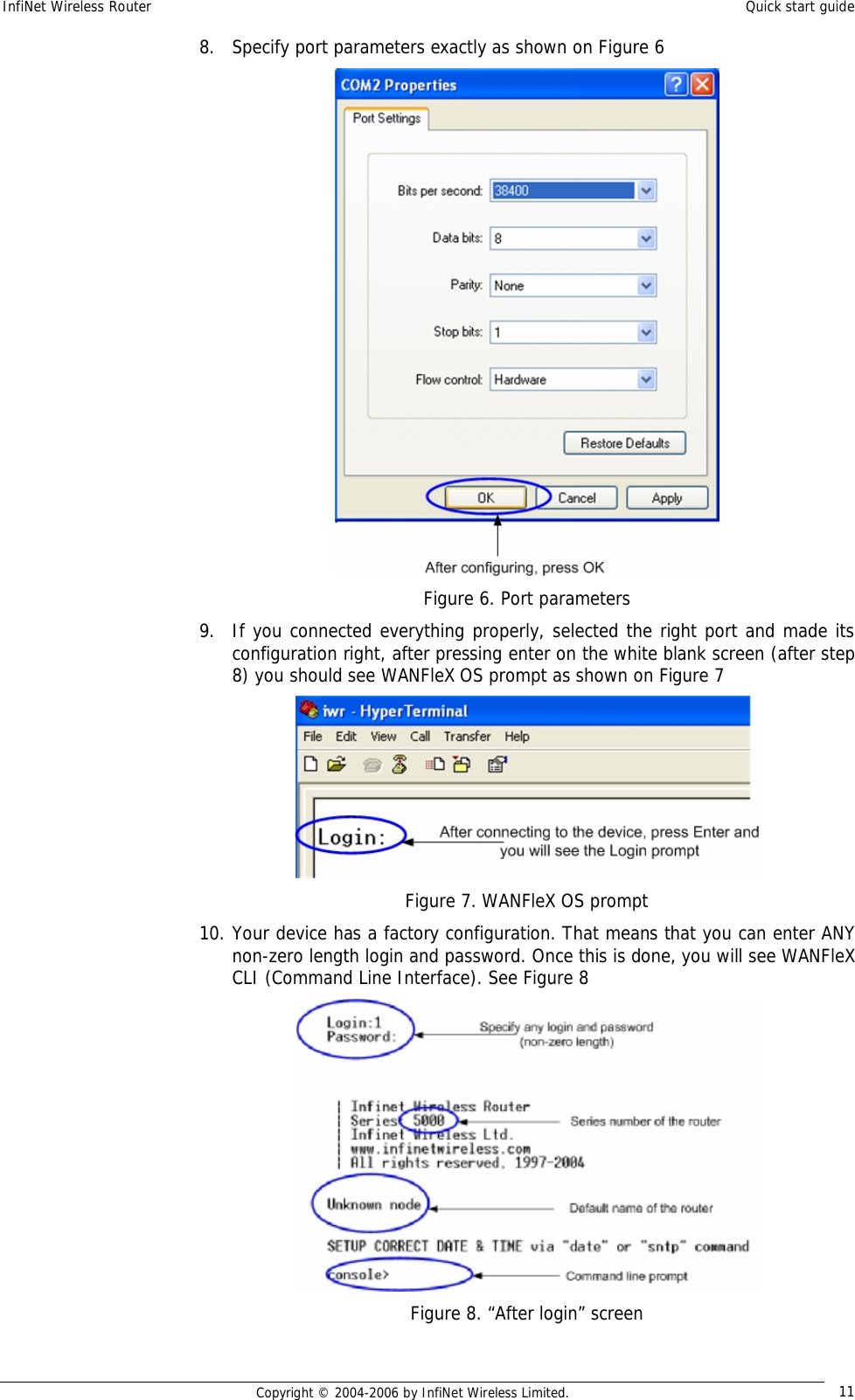
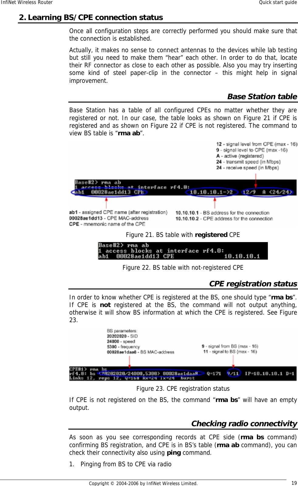
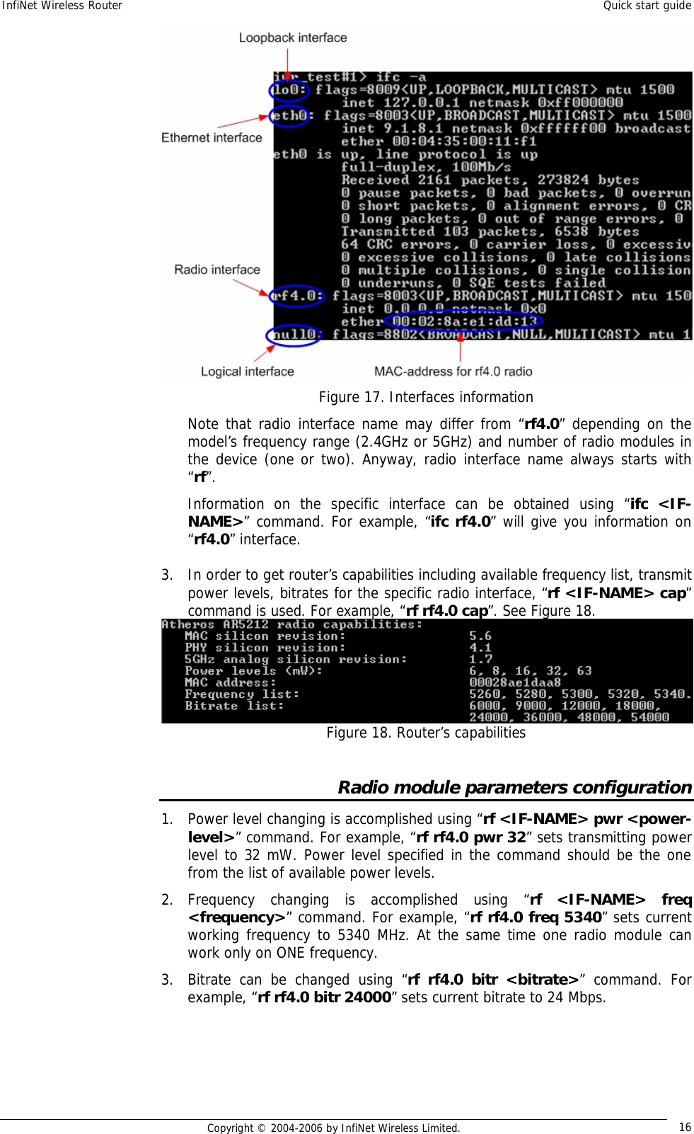
![InfiNet Wireless Router Quick start guide Copyright © 2004-2006 by InfiNet Wireless Limited. 15 2. Initial setup Once you have got the access to the router via Telnet, you can perform initial router setup. Run telnet application (Start->Run) using IP-address that was assigned on the eth0 interface of the router (for example, 9.1.8.1) First of all, let us list some useful commands that should be remembered. • “help” – lists all available commands in the router • “config show” (or “co sh” for short) – shows router’s current configuration • “config save” (or “co sa” for short) – saves router’s current configuration • “restart y” – immediate router reboot. Reboot lasts for 15 seconds (approximately) and during this time you will not be able to control it over Telnet • “quit” – finishes current configuration session The maximum number of concurrent Telnet sessions per one router is five. System parameters Once you’ve got access to the router, the most common thing to be done in the first turn is to set up some basic system parameters: • System name. System name is specified by the following command: system name [system_name] • System user. This parameter will be used as a login: system user [user_name] • System password. System password is used as a password while login: system password [password] • System prompt. This command will change current command line interface prompt: system prompt [any_word] Also, it may be useful to know firmware version that is currently available in the router and router’s serial number. “Sys ver” command can be used for this purpose (Figure 16): Figure 16. System version Learning router’s capabilities 1. In order to learn current interfaces configuration, execute “co sh ifc” command 2. In order to learn all configured interfaces, their states and statistics, execute “ifc –a” command. See Figure 17.](https://usermanual.wiki/Infinet-Wireless/R5000-L.Quick-Start-Manual/User-Guide-651429-Page-17.png)
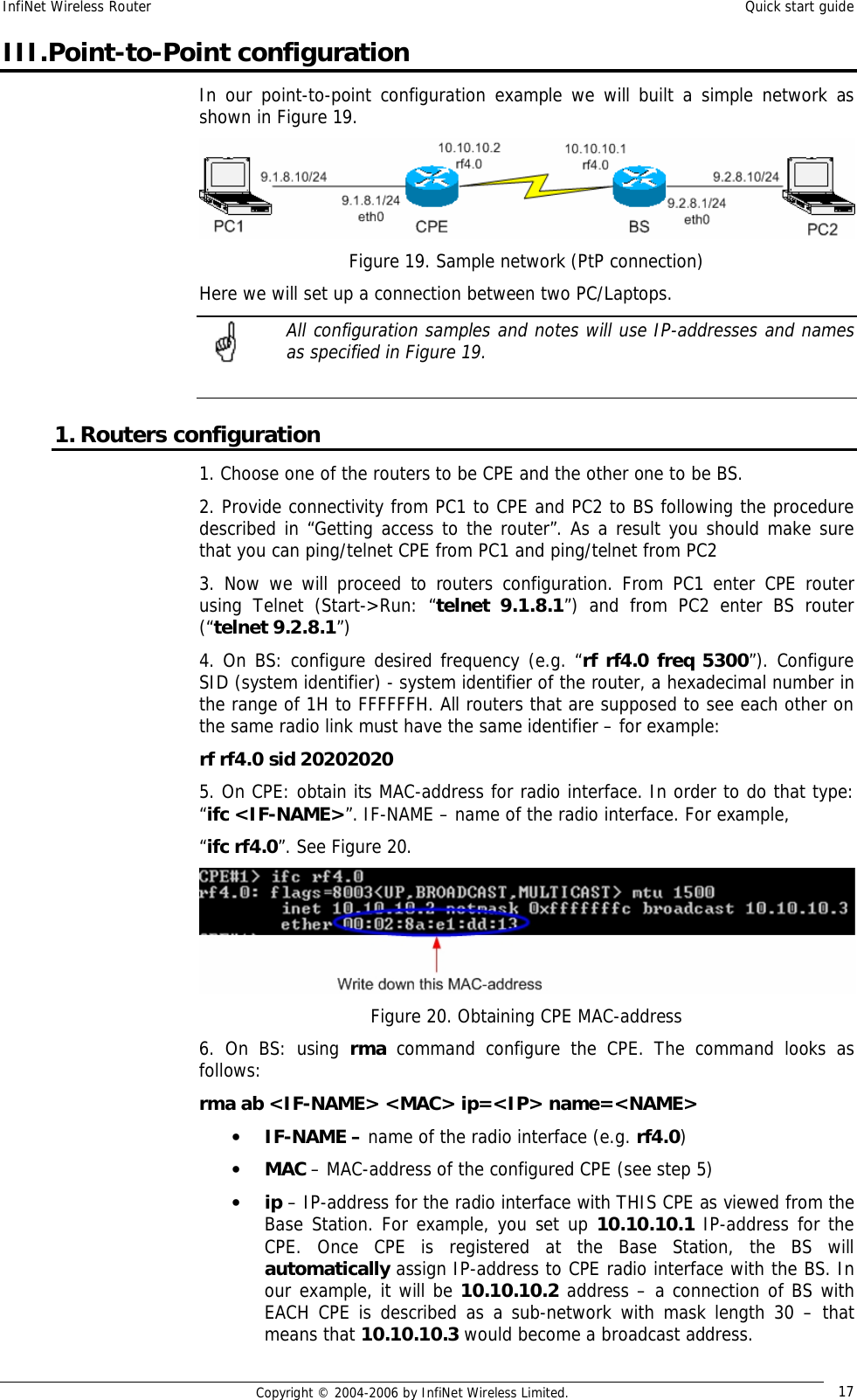
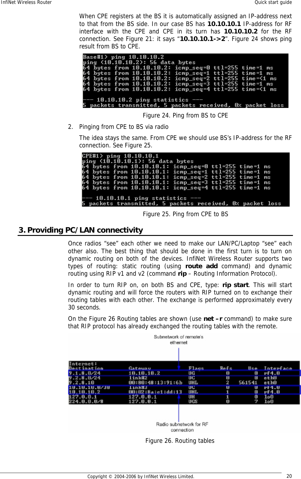
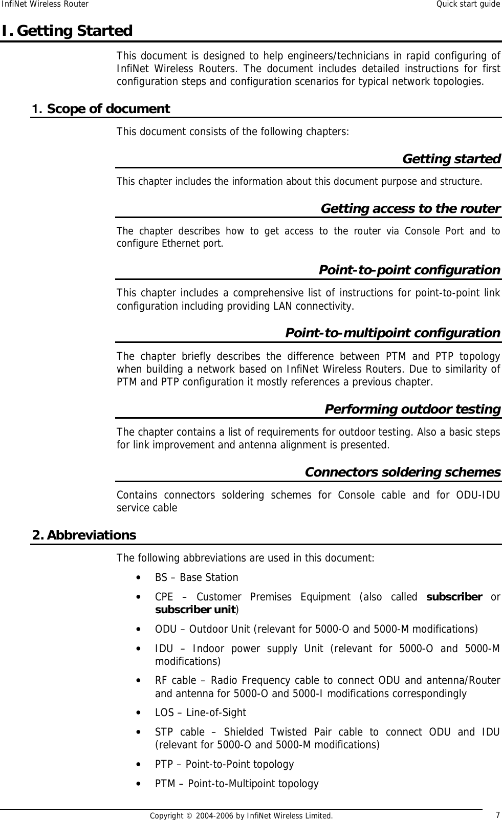
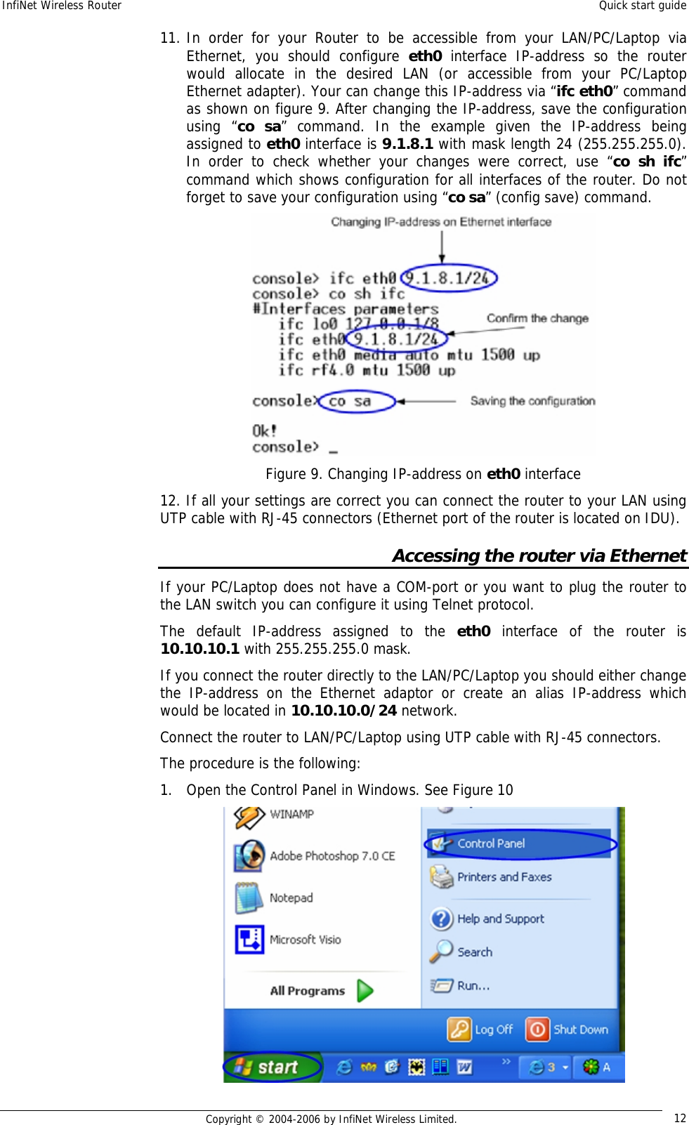
![InfiNet Wireless Router Quick start guide Copyright © 2004-2006 by InfiNet Wireless Limited. 18 • NAME – CPE’s mnemonic name. In our sample network this configuration string will look as follows: rma ab rf4.0 00028ae1dd13 ip=10.10.10.1 name=CPE VERY IMPORTANT! ETHERNET IP-ADDRESS AND IP-ADDRESS FOR RADIO INTERFACE MUST BE IN DIFFERENT NETWORKS This warning is very important. That means that if you have 10.10.10.1/24 address on the Ethernet interface you cannot have any of 10.10.10.0/24 addresses on your radio interface. 7. On BS: type “rma start”. This will run Routed Multiple Access Protocol. From this moment BS will wait for the configured CPEs (in our case it’s only one CPE) for the registration request. 8. On CPE: we need to configure our BS for this CPE. “rma bs” command is used for this purpose. Generally, each CPE can be configured for several BS. But in our example we have only one BS to establish a PTP link. The syntax for BS configuring is the following: rma bs <IF-NAME> SID/[MINSPEED/]SPEED <FREQ-LIST> • <IF-NAME> - radio interface name (e.g. rf4.0) • SID – System identifier of the BS you want to connect to. In our case it will be 20202020 (see step 4) • MINSPEED – if autobitrate mechanism is used (see below) this value will set the minimal value for the bitrate. This parameter is optional. If skipped, the lowest available bitrate will be used • SPEED – BS requested connection speed. This speed should not be higher than maximal available bitrate for the CPE (see capabilities of the router). If auotbitrate is not set, BS will work with CPE on this speed. If autobitrate is set, BS will transmit on the highest reachable (and available) bitrate and CPE will transmit on highest reachable speed but not higher than SPEED value • FREQ-LIST – list of frequencies on which the BS should be searched. It can be one or several frequencies. In our example the most evident thing that we must write is: rma rf4.0 20202020/24000 5300 9. On CPE: type “rma start”. This will start Routed Multiple Access Protocol for the CPE and it will immediately start “searching” for the configured BS by sending registration requests. 10. On BS: turn on polling mode on. Polling mode (Wireless Marker Access) is STRONGLY RECOMMENDED to be used in ALL cases as well as RMA protocol. In order to turn polling on, please type: rma <IF-NAME> poll In our case, rma rf4.0 poll Polling mode is turned on ONLY for the Base Station. This will include ALL Base Station’s CPEs into the polling circleйо! 12. Do not forget to save the configuration using “co sa” command on both CPE and BS](https://usermanual.wiki/Infinet-Wireless/R5000-L.Quick-Start-Manual/User-Guide-651429-Page-20.png)