Infinet Wireless R5000-L InfiNet Wireless 5.8 GHz Wireless Router User Manual InfiNet Wireless R5000 Technical
Infinet Wireless Limited InfiNet Wireless 5.8 GHz Wireless Router InfiNet Wireless R5000 Technical
Contents
- 1. Quick Start Manual
- 2. Users Manual
Users Manual
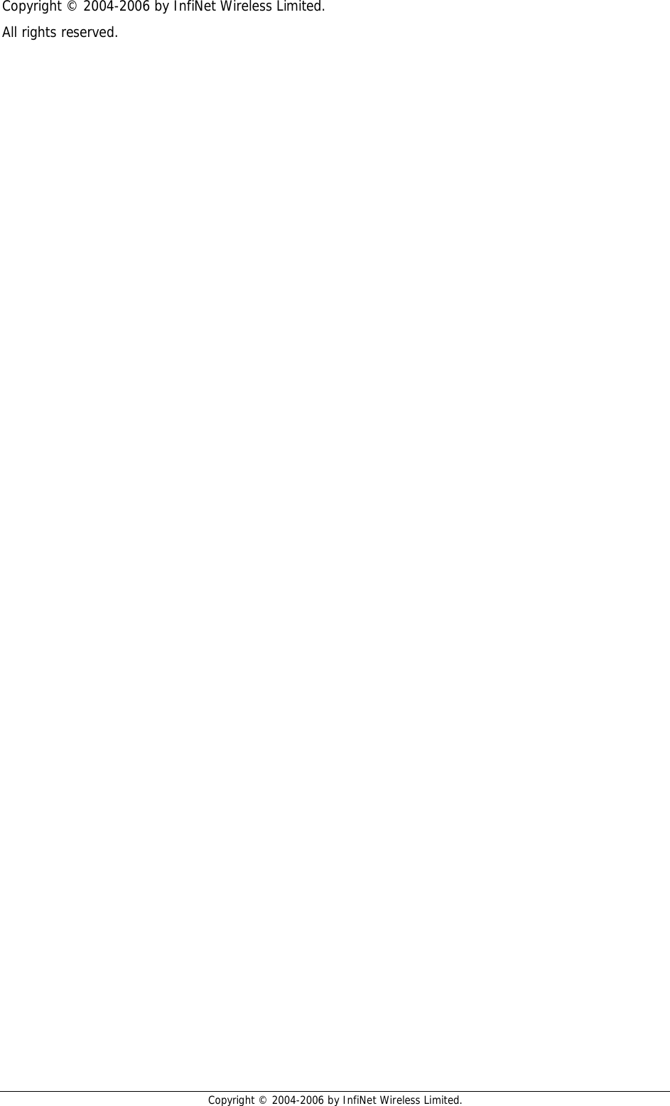
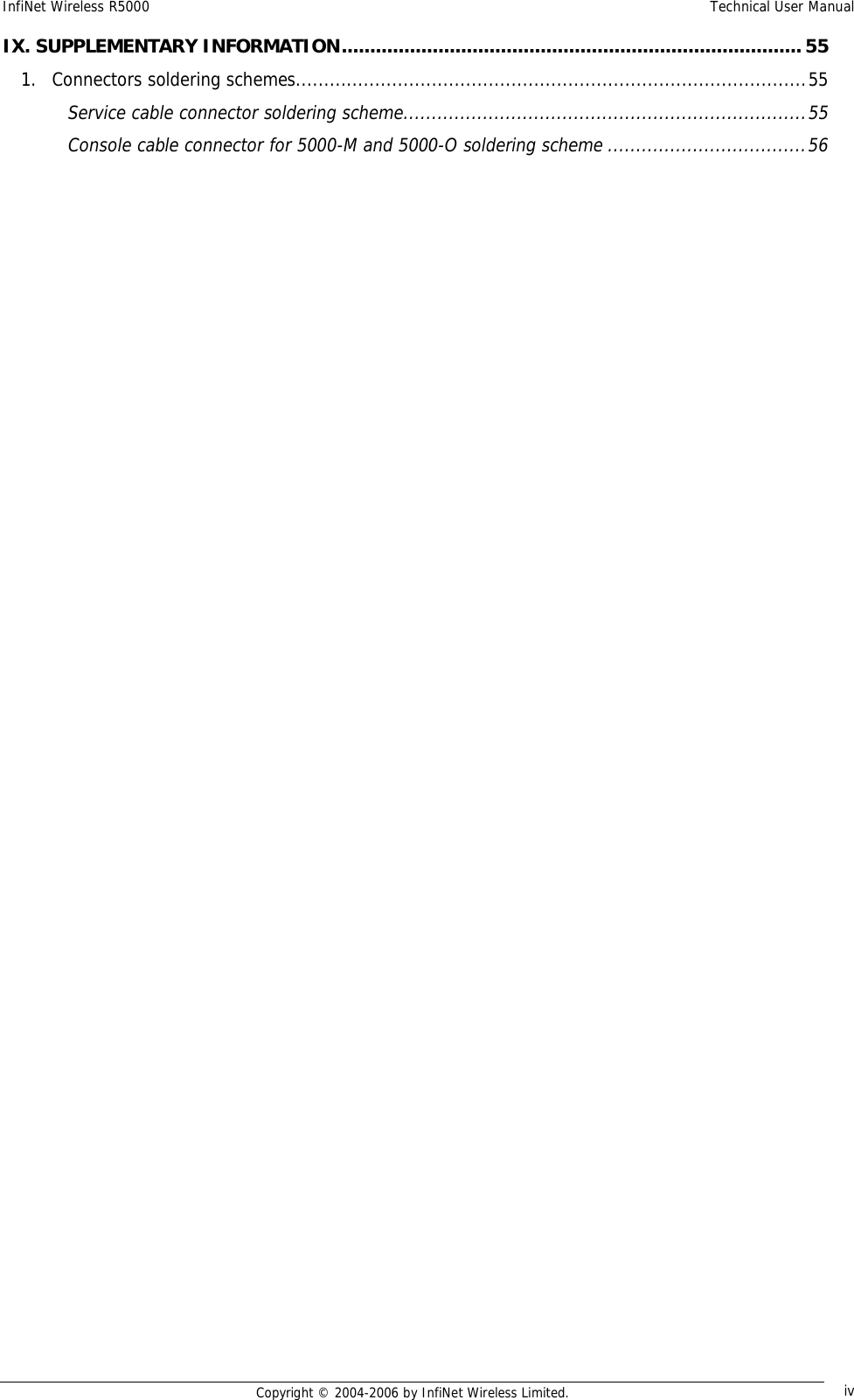
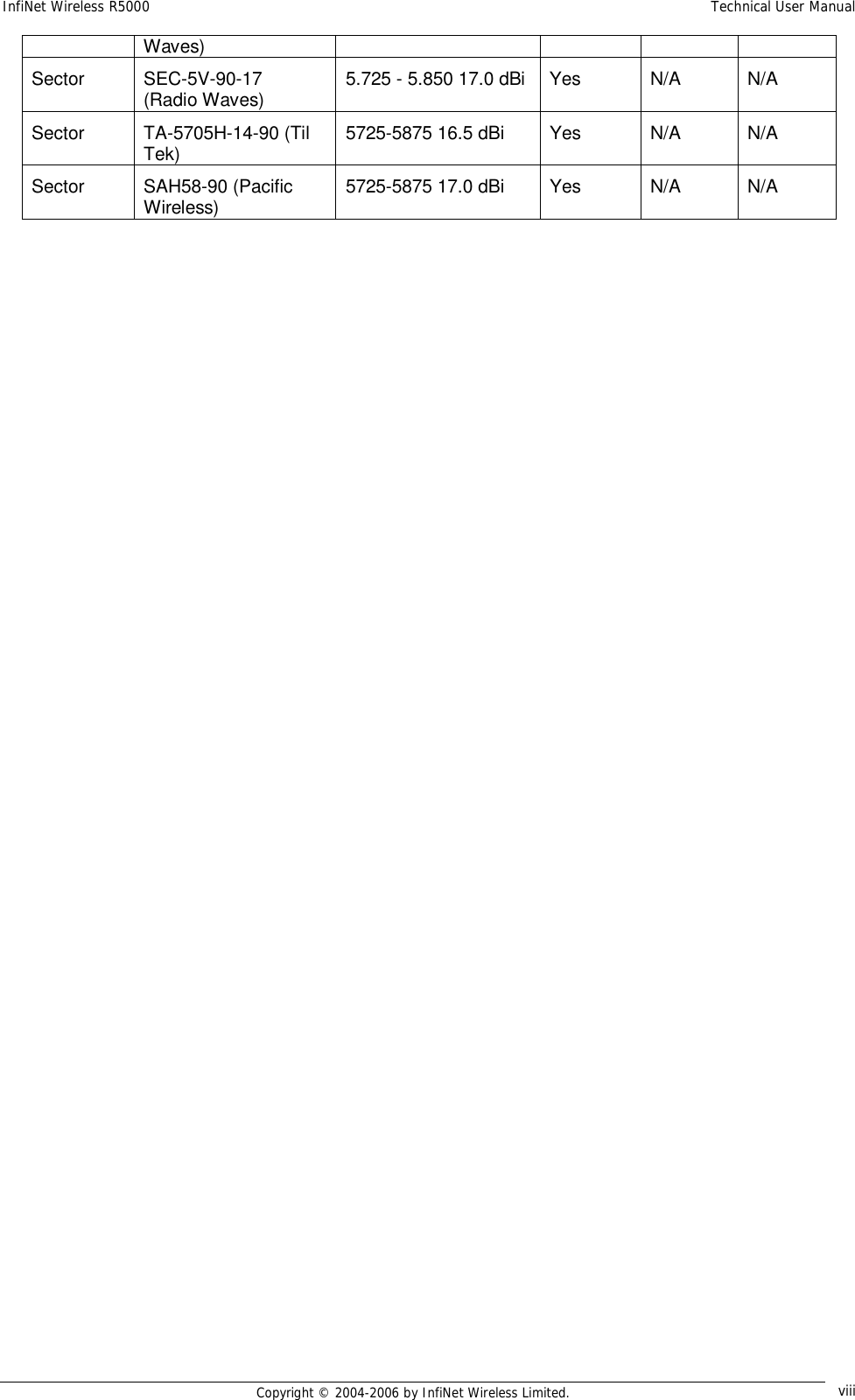
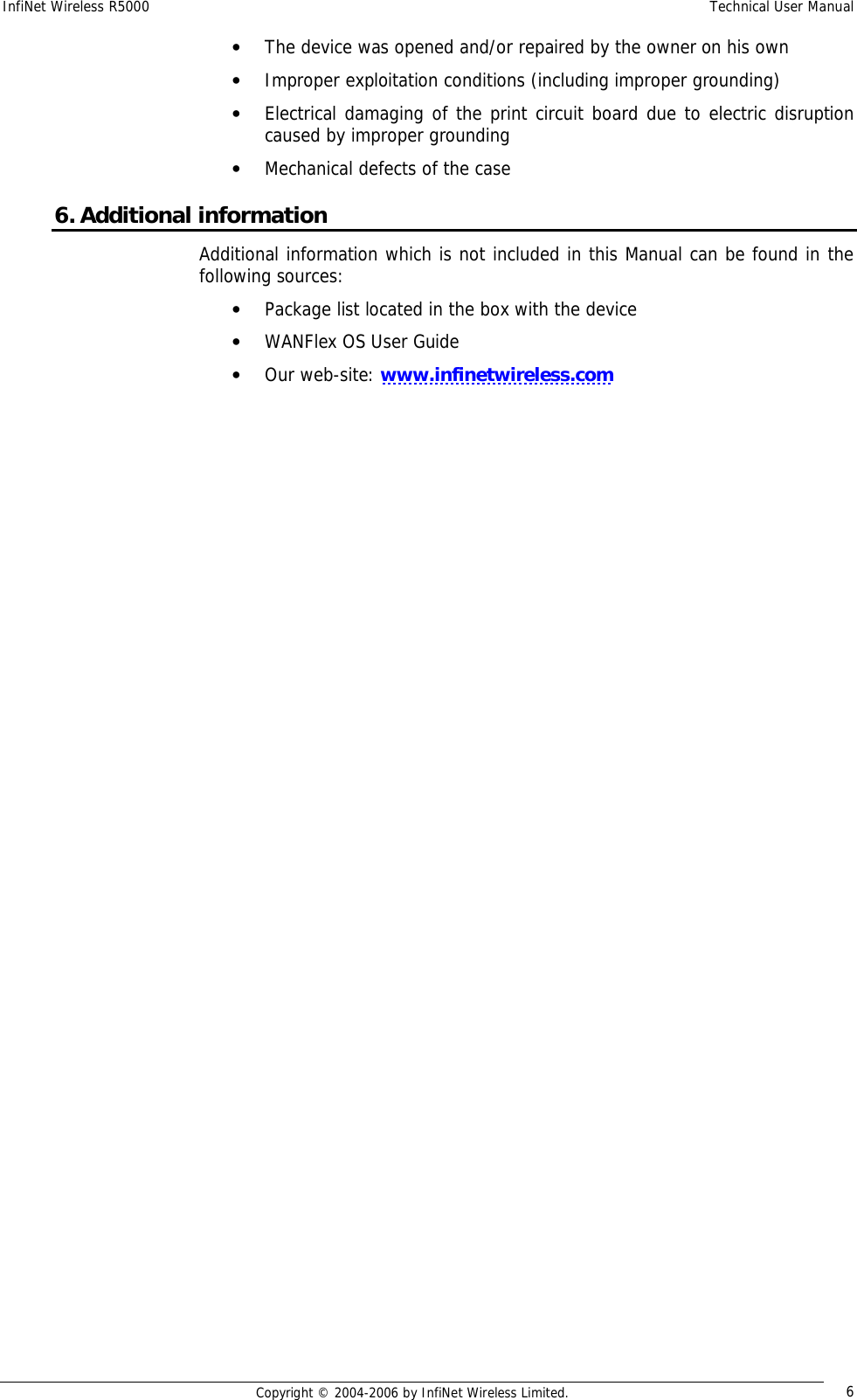
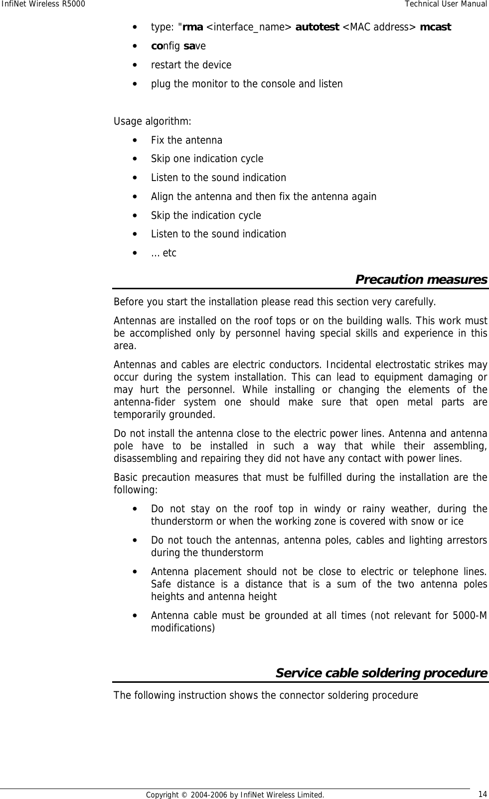
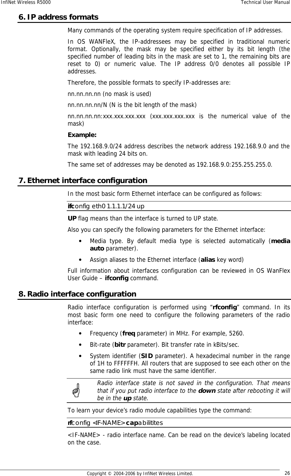
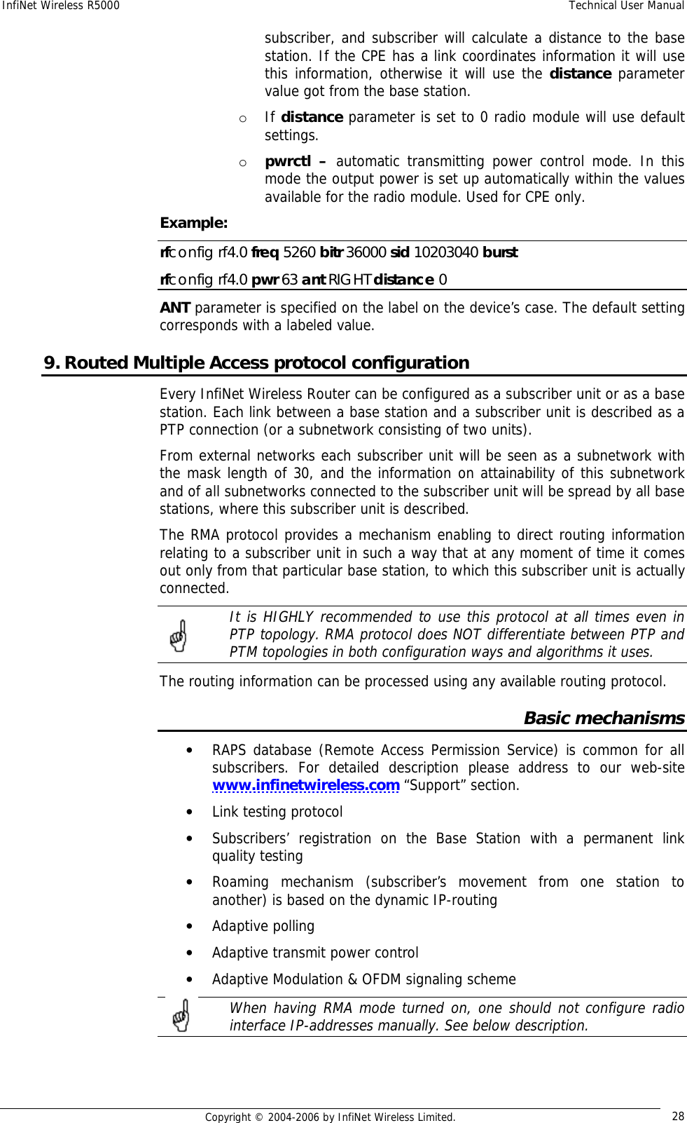
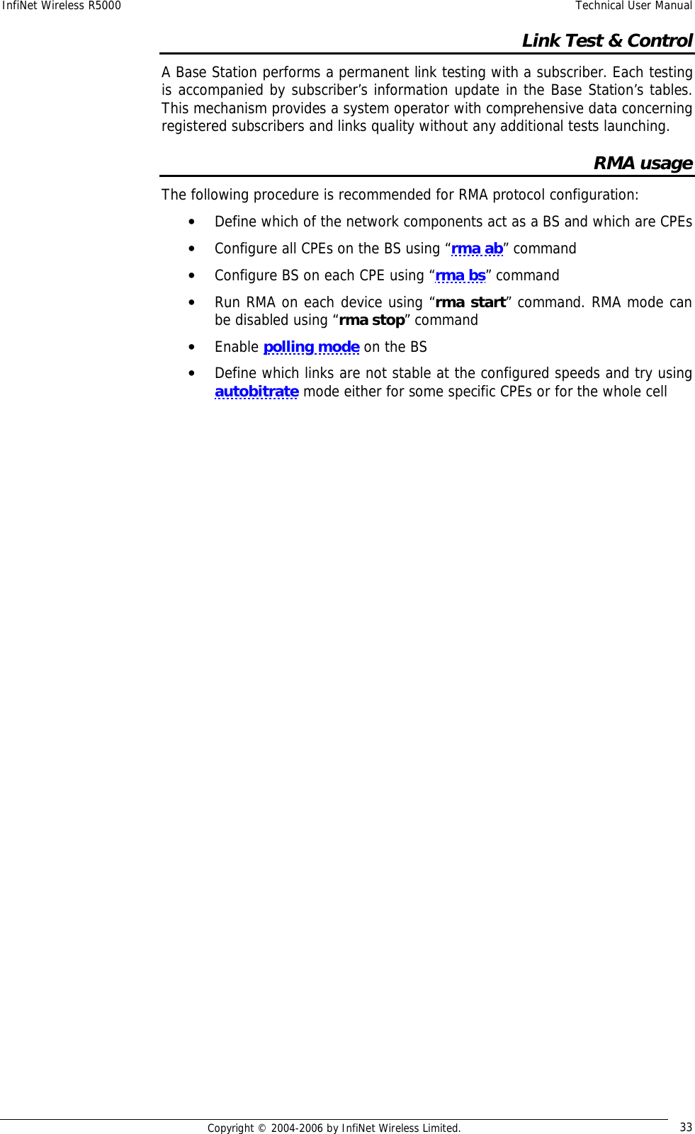
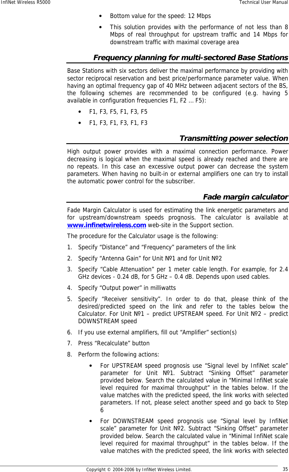
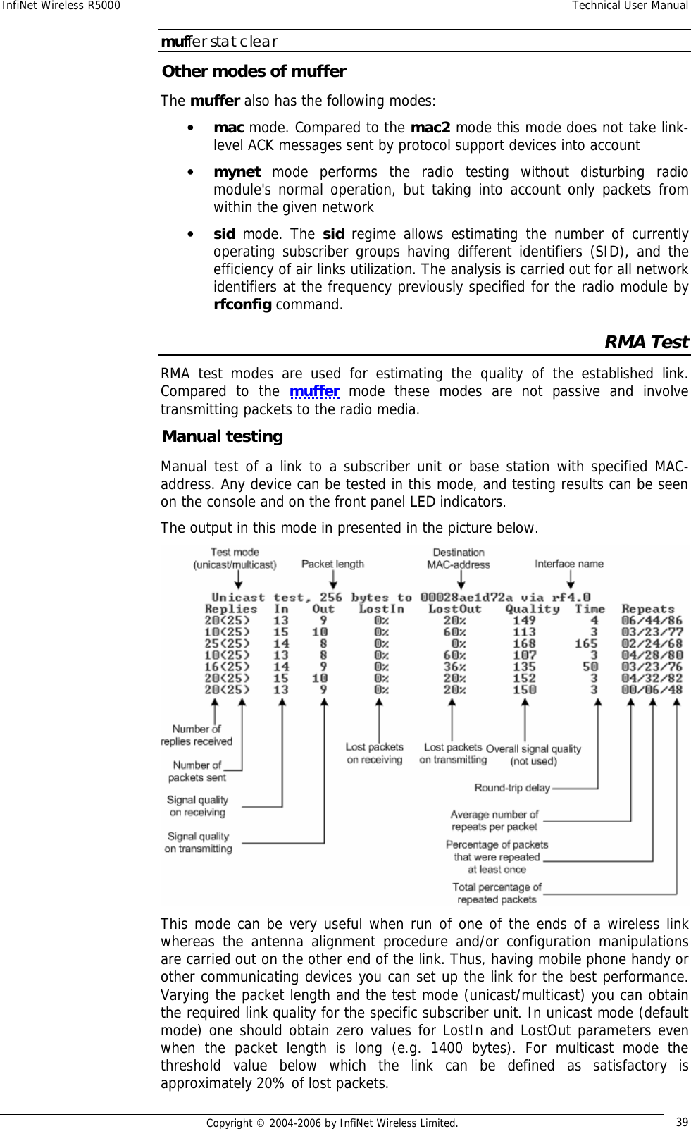
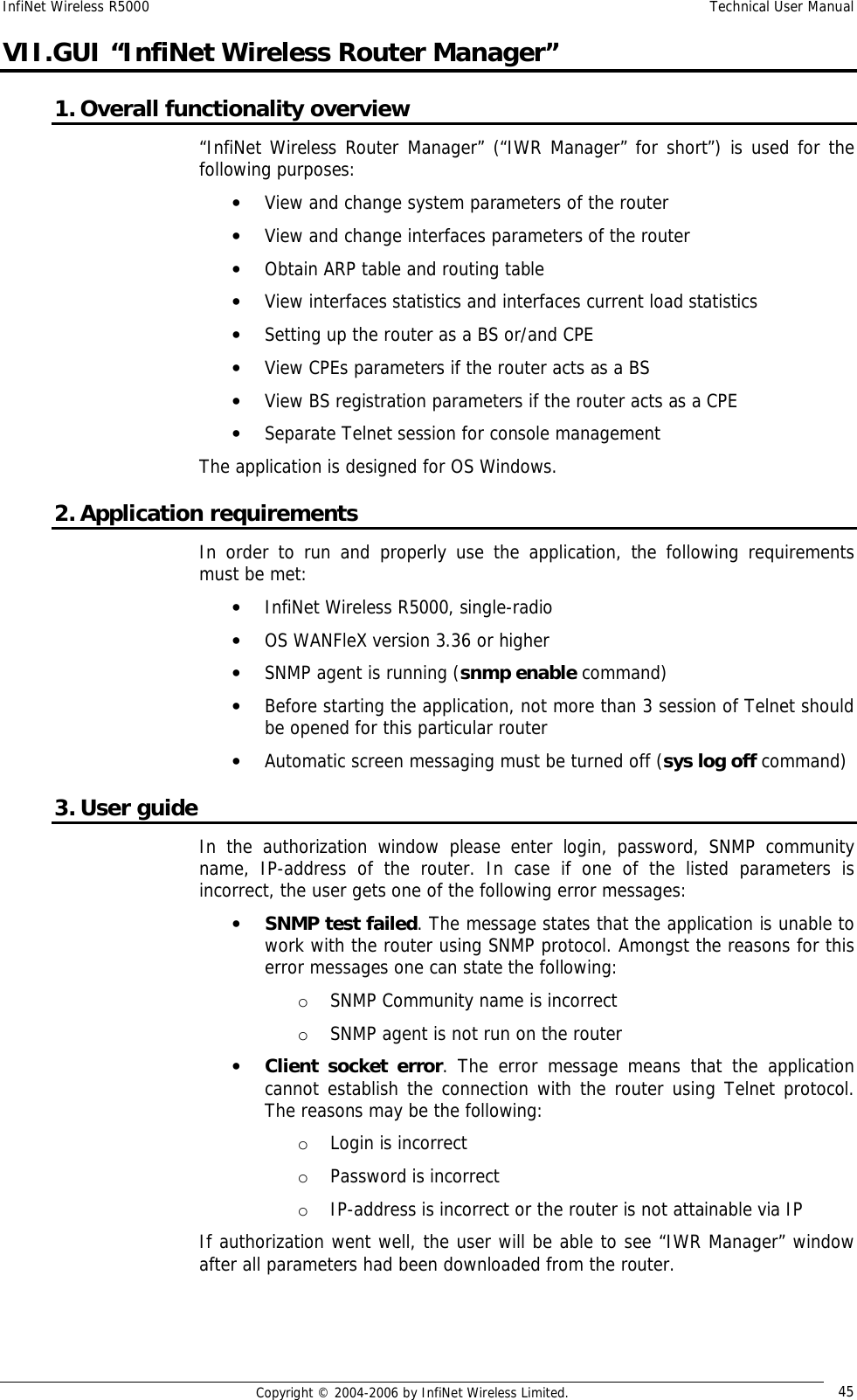
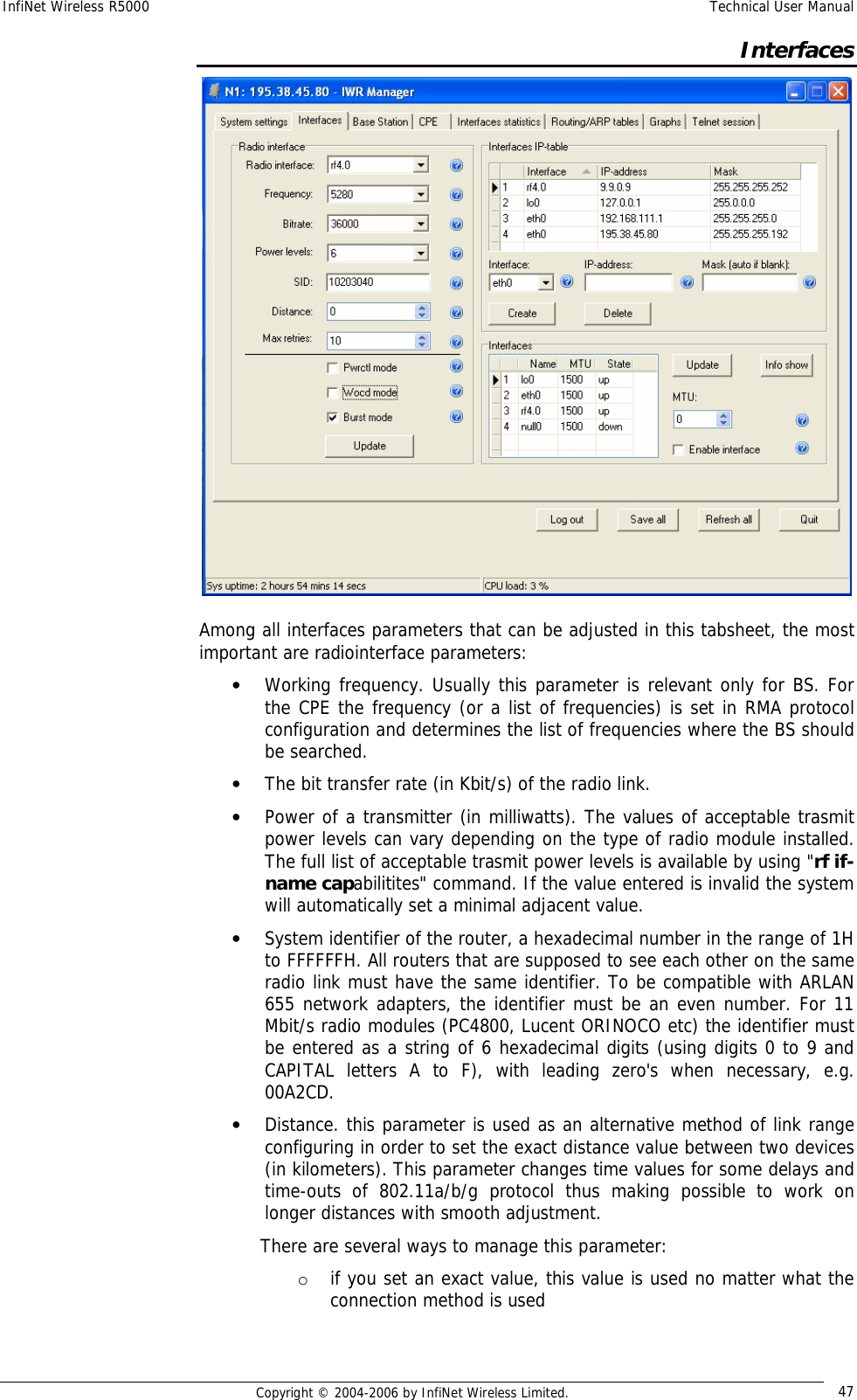
![InfiNet Wireless R5000 Technical User Manual Copyright © 2004-2006 by InfiNet Wireless Limited. 29 Base Station configuration BS is configured by specifying all of its CPEs using “rma ab” command. The command format looks as follows: rma ab <IFNAME> MAC ip=MYIP [name=NAME] [options] “Rma ab” parameters: • IFNAME – name of the radio interface • MAC – MAC-address of the CPE. In order to obtain this address please use one of the following commands on the CPE: o ifconfig –a o rfconfig <IFNAME> capabilities • MYIP – IP address of the connection as seen from the base station (mask length equals 30). IP-address for the CPE radio interface is assigned automatically • NAME - subscriber's mnemonic name (up to 20 symbols without spaces) • Options can be the following: o –disable|-enable - disables and enables the RMA mechanism for the CPE correspondingly o -del : removes the specified parameters from the BS configuration table To review current BS tables containing all its subscribers use “rma ab” command. rma ab command shows the status of all subscriber units registered on the base station and current connection quality, as shown on the following example: 1 2 3 4 5 6 7 ab1 00028ae1d72a NewRWR.0.1 9.9.0.1->2 11/8 A/B/P <18/36> ab2 00028ae1d795 NewRWR.0.5 9.9.0.5 Fields description: Field# Description 1 System assigned device’s name. Can be used instead of a MAC-address while configuring 2 Subscriber unit MAC address. 3 Unit mnemonic name. 4 IP-addresses: (base station)>(subscriber unit). The address of a subscriber unit is included into the table after successful registration of the unit. 5 Current connection quality measured in relative units from 0 to 16. 0 indicates the weakest signal quality, 16 – the strongest. <signal level from CPE>/<signal level from BS> 6 Status field. A – active](https://usermanual.wiki/Infinet-Wireless/R5000-L.Users-Manual/User-Guide-651430-Page-37.png)
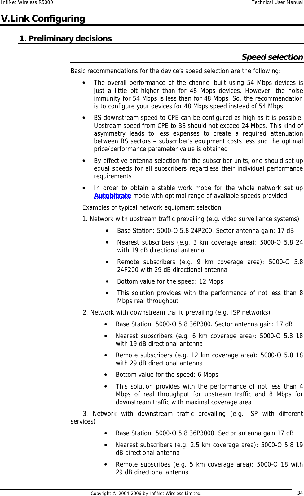
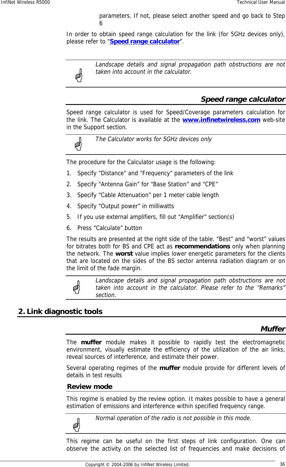
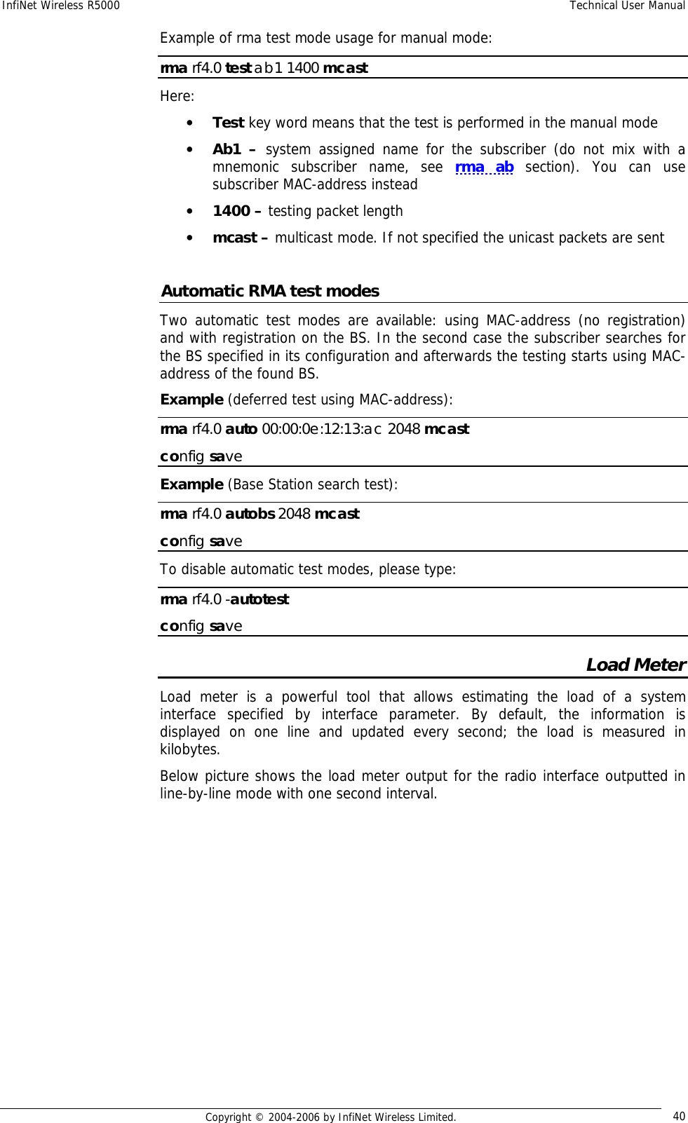
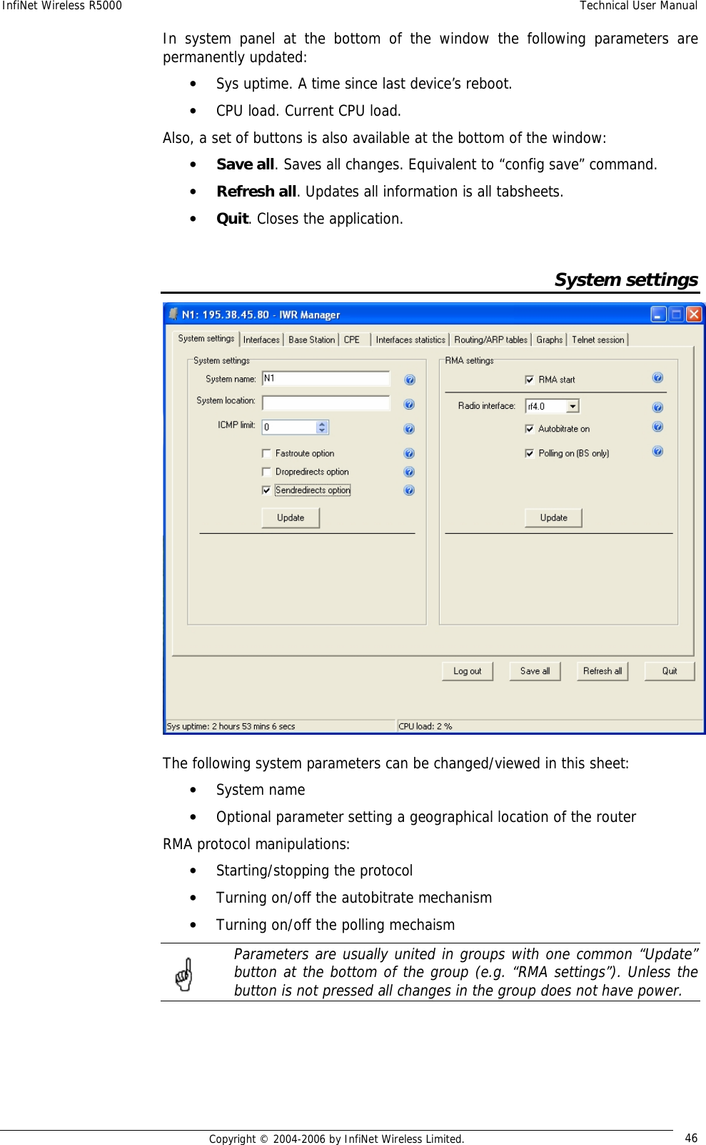
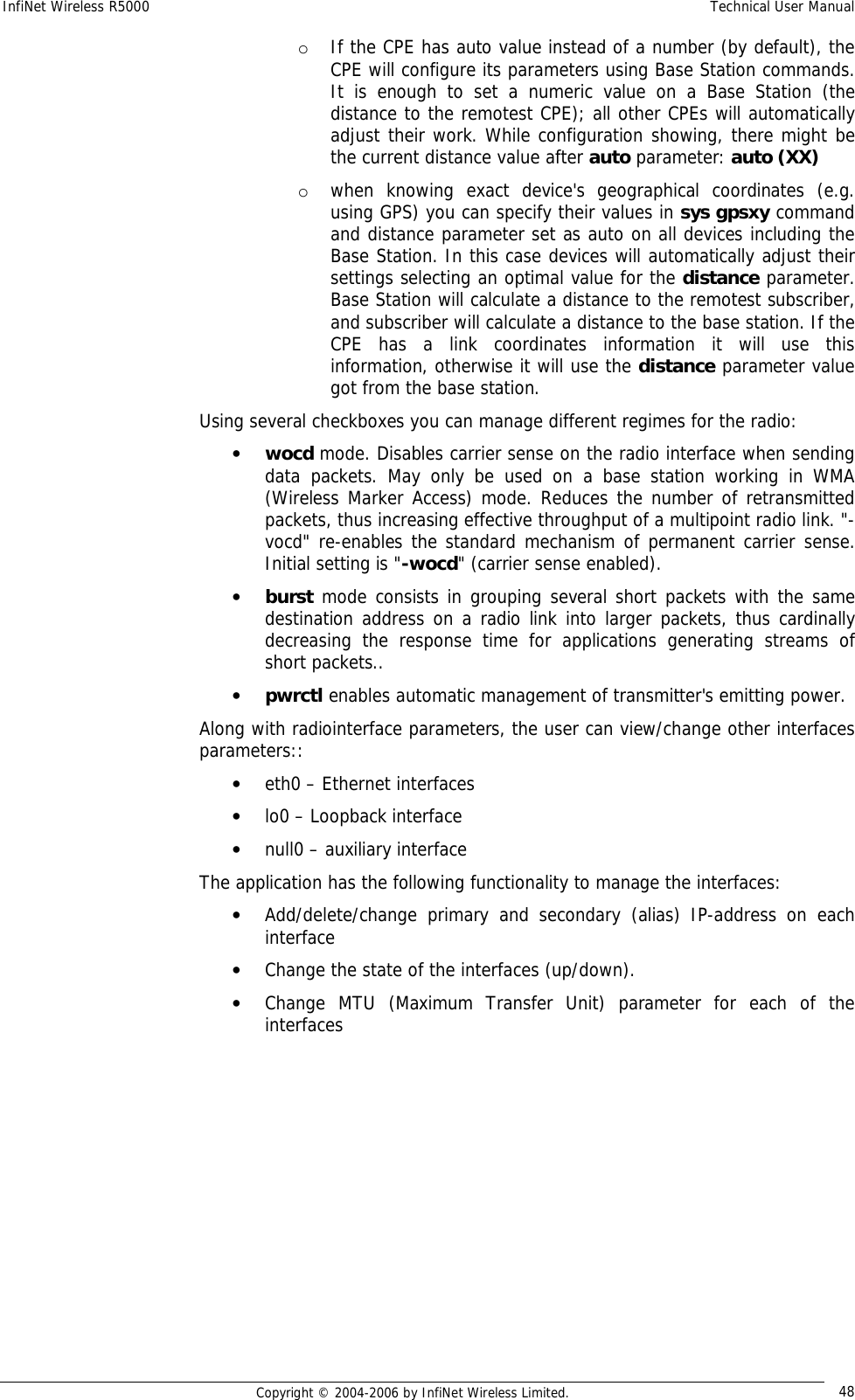
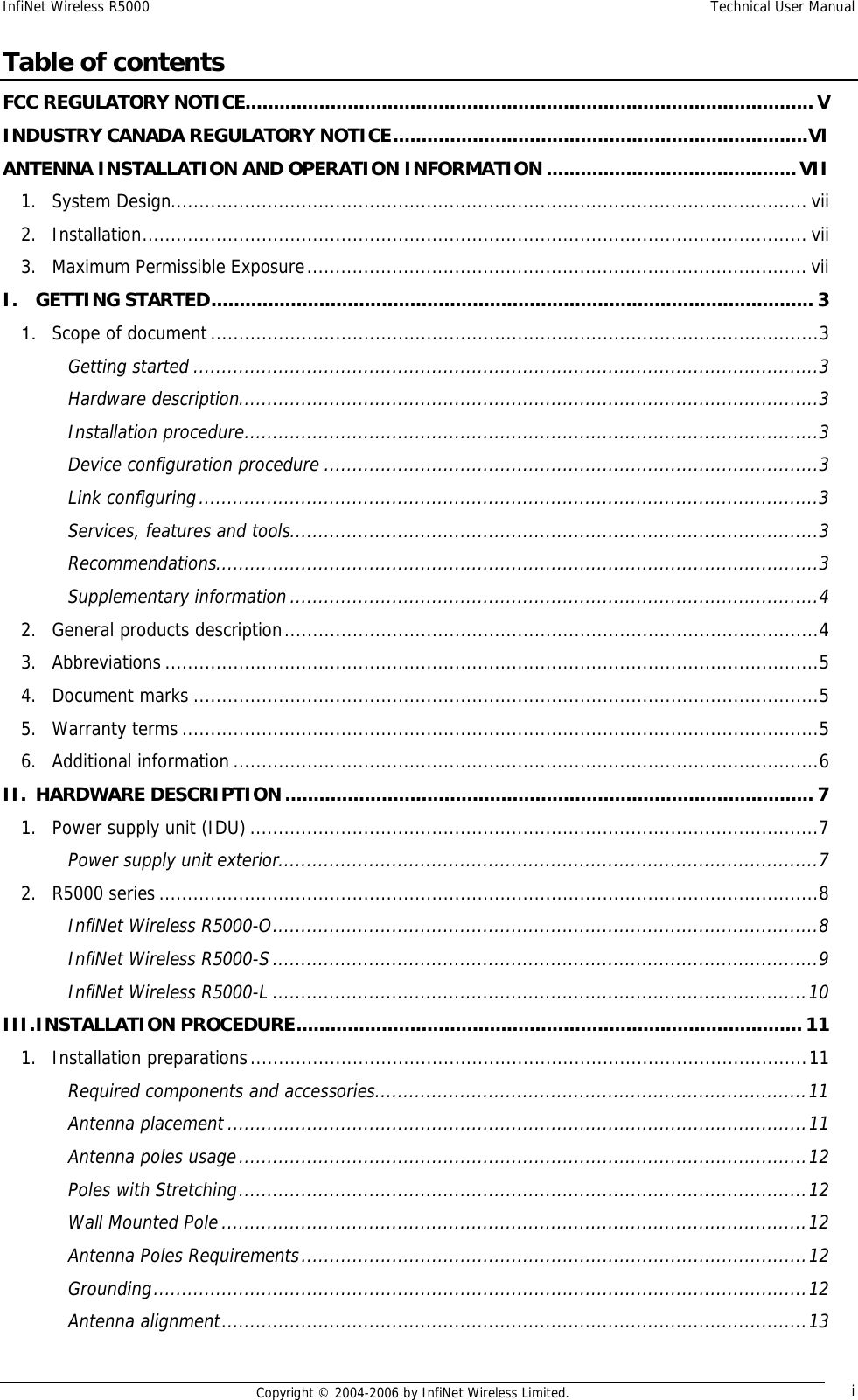
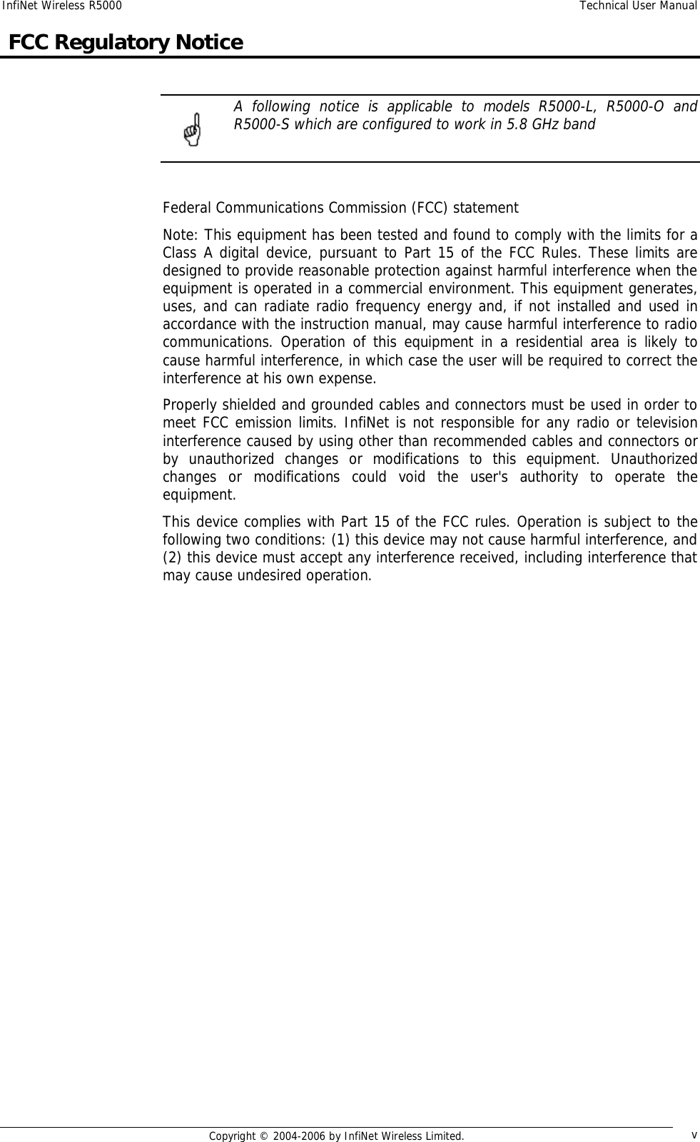
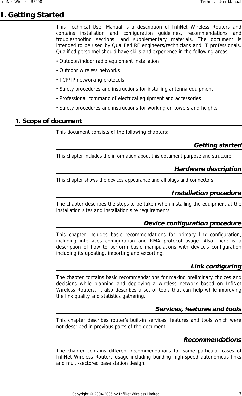
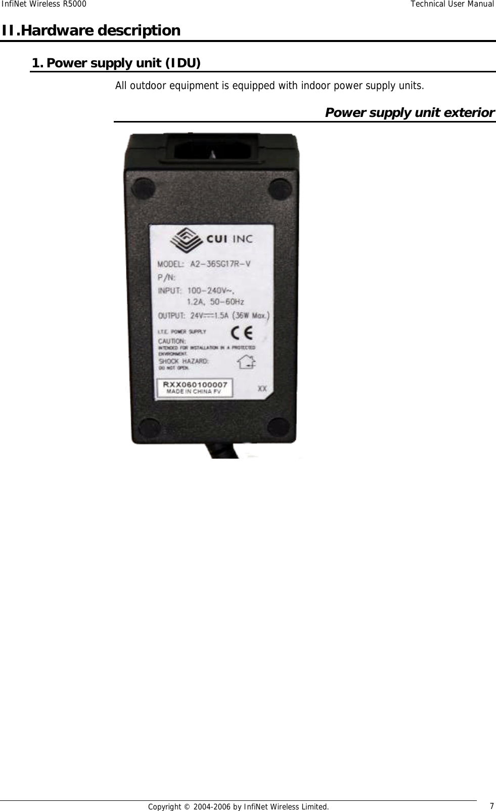
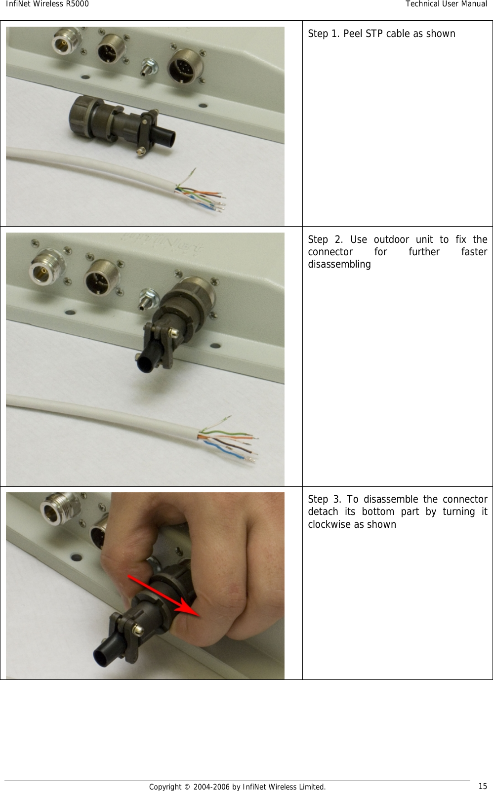
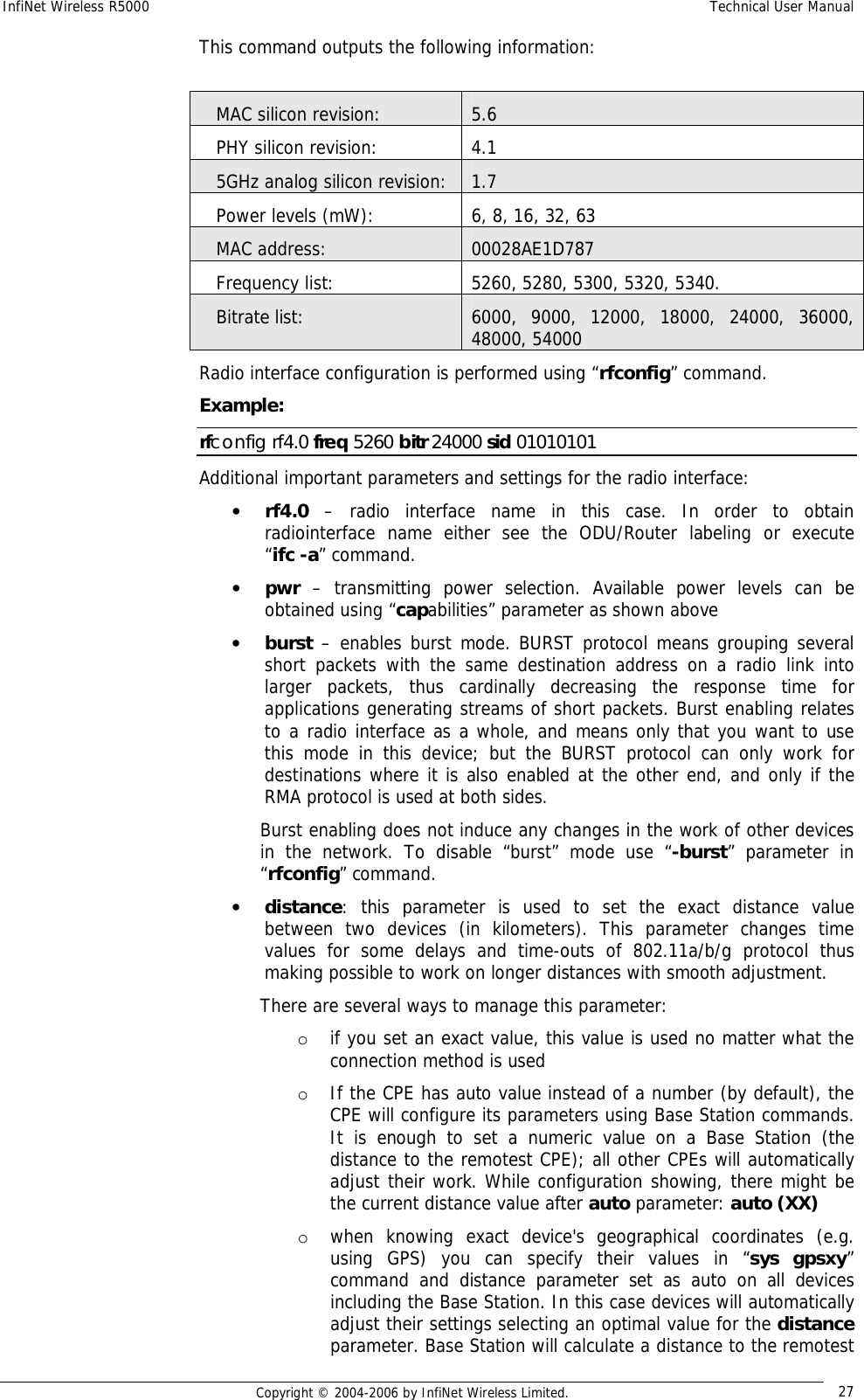
![InfiNet Wireless R5000 Technical User Manual Copyright © 2004-2006 by InfiNet Wireless Limited. 30 B – burst mode on P – polling mode on 7 <transmitting speed>/<receiving speed> CPE configuration CPE configuration is performed using “rma bs” command. For each subscriber one can specify several base stations at which the CPE can be registered (see Roaming section). The command syntax looks as follows: rma bs <IF-NAME> sid/speed[/minspeed] freq [,freq...] [-del] When executed without parameters, the RMA BS command displays the status of the base station selected and the current connection quality. The command has the following parameters: • IF-NAME - the name of a radio interface • sid - a network identifier • speed - requested connection speed (bitrate) in KBit/s (if autobitrate mode is turned on, this parameter sets the highest possible speed). The list of available speeds can be displayed by "rfconfig <IF-NAME> bitr" command and depends on radio module type. • Minspeed – optional parameter used in autobitrate mode. Sets the minimal value for the speed. • freq - the base station operating frequencies; any number of frequencies may be specified, as a list of individual frequencies and/or of frequency ranges f1-f2, separated by commas. The -DEL option is used to remove the specified parameters from the subscriber unit's configuration table. Example of BS configuration on the CPE: rma bs rf4.0 01010101/24000 5260, 5280 If you want this CPE to attempt to connect to another Base Station, you should specify it in a separate line with different frequencies and/or bitrate. “rma bs” command executed without parameters shows current registration of the CPE on the BS. Еxample: rf4.0: bs (10101011/24000,5280) 00028aeb54d4 Q=155 7/6 IP=1.1.1.1 Links 13, reps 13, Q=155 Rx=18 Tx=24 burst Here: • rf4.0 – name of the interface • 101010011 – SID • 24000 – configured maximum speed (upstream to BS) • 5280 – working frequency • 00028aeb54d4 – MAC-address of the BS at which the registration was performed • Q (1st entry)– base signal quality level • Q (2nd entry) – current signal quality level](https://usermanual.wiki/Infinet-Wireless/R5000-L.Users-Manual/User-Guide-651430-Page-38.png)