Infinet Wireless R5000-S InfiNet Wireless 5.8 GHz Wireless Router User Manual InfiNet Wireless R5000 Technical
Infinet Wireless Limited InfiNet Wireless 5.8 GHz Wireless Router InfiNet Wireless R5000 Technical
Contents
- 1. Quick Start Users Guide
- 2. Users Manual
Users Manual

Copyright © 2004-2006 by InfiNet Wireless Limited. 1
Revision date: 24 April 2006
InfiNet Wireless R5000
Technical User Manual

Copyright © 2004-2006 by InfiNet Wireless Limited. 2
Copyright © 2004-2006 by InfiNet Wireless Limited.
All rights reserved.

InfiNet Wireless R5000 Technical User Manual
Copyright © 2004-2006 by InfiNet Wireless Limited. i
Table of contents
FCC REGULATORY NOTICE....................................................................................................V
INDUSTRY CANADA REGULATORY NOTICE.........................................................................VI
ANTENNA INSTALLATION AND OPERATION INFORMATION............................................VII
1. System Design................................................................................................................vii
2. Installation.....................................................................................................................vii
3. Maximum Permissible Exposure........................................................................................vii
I. GETTING STARTED..........................................................................................................3
1. Scope of document...........................................................................................................3
Getting started..............................................................................................................3
Hardware description......................................................................................................3
Installation procedure.....................................................................................................3
Device configuration procedure.......................................................................................3
Link configuring.............................................................................................................3
Services, features and tools.............................................................................................3
Recommendations..........................................................................................................3
Supplementary information.............................................................................................4
2. General products description..............................................................................................4
3. Abbreviations...................................................................................................................5
4. Document marks..............................................................................................................5
5. Warranty terms................................................................................................................5
6. Additional information.......................................................................................................6
II. HARDWARE DESCRIPTION.............................................................................................7
1. Power supply unit (IDU)....................................................................................................7
Power supply unit exterior...............................................................................................7
2. R5000 series....................................................................................................................8
InfiNet Wireless R5000-O................................................................................................8
InfiNet Wireless R5000-S................................................................................................9
InfiNet Wireless R5000-L..............................................................................................10
III. INSTALLATION PROCEDURE.........................................................................................11
1. Installation preparations..................................................................................................11
Required components and accessories............................................................................11
Antenna placement......................................................................................................11
Antenna poles usage....................................................................................................12
Poles with Stretching....................................................................................................12
Wall Mounted Pole.......................................................................................................12
Antenna Poles Requirements.........................................................................................12
Grounding...................................................................................................................12
Antenna alignment.......................................................................................................13

InfiNet Wireless R5000 Technical User Manual
Copyright © 2004-2006 by InfiNet Wireless Limited. ii
Precaution measures....................................................................................................14
Service cable soldering procedure..................................................................................14
Connectors hermetic sealing..........................................................................................17
Tools to be available at the installation site.....................................................................18
2. InfiNet Wireless R5000-L and InfiNet Wireless R5000-O......................................................19
Installation guidelines...................................................................................................19
Wall mounting.............................................................................................................20
3. InfiNet Wireless R5000-S.................................................................................................20
Installation guidelines...................................................................................................20
Wall mounting kit assembling........................................................................................21
Pole mounting kit assembling........................................................................................22
Low diameter pole mounting kit assembling....................................................................22
IV. DEVICE CONFIGURATION INSTRUCTIONS...................................................................23
1. Initial settings configuration procedure..............................................................................23
2. Router interfaces............................................................................................................23
3. Command line interface (CLI)...........................................................................................24
4. Lost password recovery...................................................................................................24
5. Configuration manipulations.............................................................................................24
Printing and saving your configuration............................................................................24
Import/export..............................................................................................................25
New firmware uploading...............................................................................................25
6. IP address formats..........................................................................................................26
7. Ethernet interface configuration........................................................................................26
8. Radio interface configuration............................................................................................26
9. Routed Multiple Access protocol configuration....................................................................28
Basic mechanisms........................................................................................................28
Base Station configuration............................................................................................29
CPE configuration.........................................................................................................30
Bitrate control..............................................................................................................31
Roaming.....................................................................................................................31
Polling........................................................................................................................32
Link Test & Control......................................................................................................33
RMA usage..................................................................................................................33
V. LINK CONFIGURING.....................................................................................................34
1. Preliminary decisions.......................................................................................................34
Speed selection...........................................................................................................34
Frequency planning for multi-sectored Base Stations........................................................35
Transmitting power selection.........................................................................................35
Fade margin calculator.................................................................................................35
Speed range calculator.................................................................................................36

InfiNet Wireless R5000 Technical User Manual
Copyright © 2004-2006 by InfiNet Wireless Limited. iii
2. Link diagnostic tools........................................................................................................36
Muffer........................................................................................................................36
RMA Test....................................................................................................................39
Load Meter..................................................................................................................40
Acquiring interfaces statistics.........................................................................................41
VI. SERVICES, FEATURES AND TOOLS................................................................................42
1. Network services............................................................................................................42
MAC filter....................................................................................................................42
NAT............................................................................................................................42
IP firewall...................................................................................................................42
QoS............................................................................................................................43
Tunneling....................................................................................................................43
Routing core................................................................................................................43
2. Utilities and services........................................................................................................43
Telnet.........................................................................................................................43
Ping...........................................................................................................................43
Access control lists.......................................................................................................43
3. Routing protocols............................................................................................................44
Static..........................................................................................................................44
RIP.............................................................................................................................44
4. Management features......................................................................................................44
HTTP..........................................................................................................................44
RSH............................................................................................................................44
SNMP.........................................................................................................................44
Console......................................................................................................................44
VII. GUI “INFINET WIRELESS ROUTER MANAGER”.......................................................45
1. Overall functionality overview...........................................................................................45
2. Application requirements.................................................................................................45
3. User guide.....................................................................................................................45
System settings...........................................................................................................46
Interfaces...................................................................................................................47
Base Station................................................................................................................49
CPE – Customer Premises Equipment)............................................................................50
Interfaces statistics......................................................................................................51
Routing/ARP tables......................................................................................................52
Graphs........................................................................................................................52
VIII. RECOMMENDATIONS.............................................................................................54
1. Using InfiNet Devices for High Speeds (48, 54 Mbps)..........................................................54
2. Design of Multi-sectored Base Stations..............................................................................54
3. Asymmetrical System Design............................................................................................54

InfiNet Wireless R5000 Technical User Manual
Copyright © 2004-2006 by InfiNet Wireless Limited. iv
IX. SUPPLEMENTARY INFORMATION.................................................................................55
1. Connectors soldering schemes..........................................................................................55
Service cable connector soldering scheme.......................................................................55
Console cable connector for 5000-M and 5000-O soldering scheme...................................56

InfiNet Wireless R5000 Technical User Manual
Copyright © 2004-2006 by InfiNet Wireless Limited. v
FCC Regulatory Notice
A following notice is applicable to models R5000-L, R5000-O and
R5000-S which are configured to work in 5.8 GHz band
Federal Communications Commission (FCC) statement
Note: This equipment has been tested and found to comply with the limits for a
Class A digital device, pursuant to Part 15 of the FCC Rules. These limits are
designed to provide reasonable protection against harmful interference when the
equipment is operated in a commercial environment. This equipment generates,
uses, and can radiate radio frequency energy and, if not installed and used in
accordance with the instruction manual, may cause harmful interference to radio
communications. Operation of this equipment in a residential area is likely to
cause harmful interference, in which case the user will be required to correct the
interference at his own expense.
Properly shielded and grounded cables and connectors must be used in order to
meet FCC emission limits. InfiNet is not responsible for any radio or television
interference caused by using other than recommended cables and connectors or
by unauthorized changes or modifications to this equipment. Unauthorized
changes or modifications could void the user's authority to operate the
equipment.
This device complies with Part 15 of the FCC rules. Operation is subject to the
following two conditions: (1) this device may not cause harmful interference, and
(2) this device must accept any interference received, including interference that
may cause undesired operation.

InfiNet Wireless R5000 Technical User Manual
Copyright © 2004-2006 by InfiNet Wireless Limited. vi
Industry Canada Regulatory Notice
A following notice is applicable to models R5000-L, R5000-O and
R5000-S which are configured to work in 5.8 GHz band
Industry Canada compliance statement
This Class B digital apparatus meets all requirements of the Canadian
Interference-Causing Equipment Regulations.
This device complies with Industry Canada specification RSS-210. Operation is
subject to the following two conditions:
(1) this device may not cause interference, and
(2) this device must accept any interference received, including interference that
may cause undesired operation of the device.
Equipment (or its transmit antenna) that is installed outdoors is subject to
licensing.
The installer of this radio equipment must ensure that the antenna is located or
pointed such that it does not emit RF fields in excess of Health Canada limits for
the general population; consult Safety Code 6, obtainable from Health Canada’s
Web site: www.hc-sc.gc.ca/rpb.
Avis de conformité aux normes d’Industrie Canada
Cet appareil numérique de la classe B respecte toutes les exigences du
Réglement sur le matériel brouilleur du Canada.
Cet appareil est conforme а la spécification RSS-210 d'Industry Canada. Son
fonctionnement est soumis aux deux conditions suivantes:
(1) cet appareil ne peut engendrer aucune interférence et
(2) il doit accepter toute interférence qu'il reзoit, y compris celles qui peuvent
altérer son fonctionnement.
L'équipement (ou son antenne émettrice) est soumis а l'obtention d'une licence
s'il est installé а l'extérieur.
L'installateur de cet équipement radio doit veiller а ce que l'antenne soit
implantйe et dirigée de maniиre а n'émettre aucun champ HF dépassant les
limites fixées pour l'ensemble de la population par Santé Canada. Reportez-vous
au Code de sécurité 6 que vous pouvez consulter sur le site Web de Santé
Canada: www.hc-sc.gc.ca/rpb

InfiNet Wireless R5000 Technical User Manual
Copyright © 2004-2006 by InfiNet Wireless Limited. vii
Antenna installation and operation information
1. System Design
Infinet Wireless, wireless routers, can be operated in both point to point and
Point to Multipoint modes, depending on equipment and system configuration.
System designers must be aware that changes to operating power levels and
antenna selection are required depending on the mode of operation of this
equipment.
Devices used exclusively for Point to Point operation are allowed to use antenna
gains greater than 6dBi without reduction of the RF power. Point to Multi-Point
operation requires the reduction of RF Power below 1Watt by the number of dB
above 6dBi antenna gain
15.247(c)(1)(iii): The operator of the spread spectrum or digitally modulated
intentional radiator or, if the equipment is professionally installed, the installer is
responsible for ensuring that the system is used exclusively for fixed, point-to-
point operations. The instruction manual furnished with the intentional radiator
shall contain language in the installation instructions informing the operator and
the installer of this responsibility
2. Installation
External antennas for InfiNet wireless equipment must be professionally
installed, due to the hazards involved in installation of equipments on towers,
building exteriors, and rooftops. A professional installer is one who is a properly
trained person whose normal job function includes this type of work. Generally
speaking a professional installer will have credentials from Narte, various
equipment suppliers, or another recognized body.
3. Maximum Permissible Exposure
This equipment this phone has been tested and meets the FCC RF exposure
guidelines when used with the antennas indicated in Table 2 below.
Worst-case distance for MPE for this product, for any of the antennas listed, is
the separation shown in Table 1.
Table 2 – Antennas certified for use with InfiNet Wireless routers
Antenna Types Notes R5000-O R5000-L R5000-S
Directional MT-486001 (MTI) 5.15-5.975 GHz 28dBi Yes Yes N/A
Directional SP1.5 (Radio Waves) 5.725 - 5.850 25.7 dBi Yes Yes N/A
Directional DA58 (Pacific
Wireless) 5,725 – 5,850 29 dBi Yes Yes N/A
Sector MT-484032/NV (MTI) 5.15-5.875 GHz 17dBi Yes N/A N/A
Sector MT-484033/NH (MTI) 5.15-5.875 GHz
16.5dBi Yes N/A N/A
Sector SEC-5V-60-18 (Radio 5.725 - 5.850 18 dBi Yes N/A
Table 1 – Maximum Permissible Exposure Data
Model Minimum Distance (worst case antenna)
R-5000-O 1.97 Meters (197 cm)
R-5000-L 1.58 Meters (158 cm)
R-5000-S 0.502 Meters (50.2 cm)

InfiNet Wireless R5000 Technical User Manual
Copyright © 2004-2006 by InfiNet Wireless Limited. viii
Waves)
Sector SEC-5V-90-17
(Radio Waves) 5.725 - 5.850 17.0 dBi Yes N/A N/A
Sector TA-5705H-14-90 (Til
Tek) 5725-5875 16.5 dBi Yes N/A N/A
Sector SAH58-90 (Pacific
Wireless) 5725-5875 17.0 dBi Yes N/A N/A

InfiNet Wireless R5000 Technical User Manual
Copyright © 2004-2006 by InfiNet Wireless Limited. 3
I. Getting Started
This Technical User Manual is a description of InfiNet Wireless Routers and
contains installation and configuration guidelines, recommendations and
troubleshooting sections, and supplementary materials. The document is
intended to be used by Qualified RF engineers/technicians and IT professionals.
Qualified personnel should have skills and experience in the following areas:
• Outdoor/indoor radio equipment installation
• Outdoor wireless networks
• TCP/IP networking protocols
• Safety procedures and instructions for installing antenna equipment
• Professional command of electrical equipment and accessories
• Safety procedures and instructions for working on towers and heights
1. Scope of document
This document consists of the following chapters:
Getting started
This chapter includes the information about this document purpose and structure.
Hardware description
This chapter shows the devices appearance and all plugs and connectors.
Installation procedure
The chapter describes the steps to be taken when installing the equipment at the
installation sites and installation site requirements.
Device configuration procedure
This chapter includes basic recommendations for primary link configuration,
including interfaces configuration and RMA protocol usage. Also there is a
description of how to perform basic manipulations with device’s configuration
including its updating, importing and exporting.
Link configuring
The chapter contains basic recommendations for making preliminary choices and
decisions while planning and deploying a wireless network based on InfiNet
Wireless Routers. It also describes a set of tools that can help while improving
the link quality and statistics gathering.
Services, features and tools
This chapter describes router’s built-in services, features and tools which were
not described in previous parts of the document
Recommendations
The chapter contains different recommendations for some particular cases of
InfiNet Wireless Routers usage including building high-speed autonomous links
and multi-sectored base station design.

InfiNet Wireless R5000 Technical User Manual
Copyright © 2004-2006 by InfiNet Wireless Limited. 4
Supplementary information
Contains supplementary information (specifications, connectors soldering
schemes and InfiNet Wireless Routers product matrix).
2. General products description
InfiNet Wireless FBWA products offer scalable, robust, flexible and cost-effective
fixed broadband wireless access solutions for carrier-class networks. Wireless
routing equipment from InfiNet Wireless is designed to implement and expand
carrier-class networks for high-speed Internet access, enterprise campus
networks, primary links for the Last Mile and backhauling traffic between cell
towers and multiple access points.
InfiNet Wireless Routers are especially applicable to regions with complex wired
infrastructures where infrastructure upgrades require costly or time-consuming
activities. Many deployments have been accomplished in regions with a dearth of
wired infrastructure where wireless solution is the only viable option for both
voice and data networks. The deployment of InfiNet Wireless Routers minimizes
both capital and operational investments for the creation of network
infrastructure.
Key product features:
• Support 2.4 GHz and 5-6 GHz bands, based on DSSS and OFDM
technologies
• Intelligent deterministic non-collision protocol using the radio spectrum
• Powerful QoS capabilities
• Security, tunneling, NAT and firewall
• Flexible network management
• VoIP functionality
• Powerful integrated diagnostic tools
InfiNet Wireless routers are generally used to create geographically spread FBWA
transport networks. In its most basic form, a wireless network built with InfiNet
Wireless routers consists of a base station and multiple subscriber units deployed
one at each end of the wireless links. The radio link operates on a single
frequency channel using Time Division Duplex (TDD) and dynamic adaptive
polling MAC protocol. The difference between a base station unit and subscriber
unit is a matter of configuration and CPU performance. Both devices have the
same common software feature set and the same common hardware platform.
The InfiNet Wireless software is not logically limited to the number of wired
hosts on the subscriber LAN.
The InfiNet Wireless routers have been developed to operate within license
exempt frequency bands which are either 2.412-2.484 GHz or 4.920 – 6,010
GHz. Different products series supports different frequency bands.
The InfiNet Wireless routers can support flexible topologies including point-to-
point links, point-to-multipoint links, high-speed transport connections
(backbones) and relay-points building. They have been designed to prevent
internal and external interference using such product features as software
selectable transmit power control, static frequency selection, asymmetrical bit-
rate/transmit power rates selection for base and subscriber units. In order to
maintain link availability, solve the “hidden node” problem and reduce the
collision rate, the product employs dynamic adaptive non-collision polling MAC
protocol that dynamically redistributes data streams between active and inactive
subscribers. Autobitrate mechanism is an optional powerful feature that provides
link reliability in case of changing conditions on the path of the link.
InfiNet Wireless R5000 Technical User Manual
Copyright © 2004-2006 by InfiNet Wireless Limited. 5
The data network built on InfiNet Wireless products is implemented as a routed
IP network which reduces flooding and broadcast messages specific to bridged
networks and to implementation of Quality-of-Service (QoS) features set. QoS
definitions per subscriber’s data flows are effectively mapped on MAC level flow
attributes.
Each device in the network can be configured using serial console port, Telnet
protocol or HTTP (web-based).
RAPS (Remote Access Permission Service) provides a whole network with a
flexible mechanism of a centralized management, configuration and monitoring.
The software/firmware is fully upgradeable for all InfiNet Wireless routers. New
firmware images can be downloaded from the InfiNet Wireless web-site
http://www.infinetwireless.com for its further uploading on the device.
3. Abbreviations
The following abbreviations are used in this document:
• BS – Base Station
• CPE – Customer Premises Equipment (also called subscriber or
subscriber unit)
• ODU – Outdoor Unit (relevant for 5000-O and 5000-M modifications)
• IDU – Indoor power supply Unit (relevant for 5000-O and 5000-M
modifications)
• RF cable – Radio Frequency cable to connect ODU and antenna/Router
and antenna for 5000-O and 5000-I modifications correspondingly
• LOS – Line-of-Sight
• STP cable – Shielded Twisted Pair cable to connect ODU and IDU
(relevant for 5000-O and 5000-M modifications)
• PTP – Point-to-Point topology
• PTM – Point-to-Multipoint topology
• RMA – Routed Multiple Access Protocol
4. Document marks
All warnings are marked with a special warning sign. One should pay
a great deal of attention to what is written in the Warning sections.
All notes are marked with a special note sign. Notes usually contain
useful comments or hints to the described section of the document.
5. Warranty terms
The manufacturer guarantees a reliable work of the product during 12 month
from the date of product installation but no later than 15 months from the date
of delivery of equipment to distributor. The warranty is not spread for the
devices which stopped working properly due to improper usage, careless
treatment, incorrect deployment or exploitation. The warranty voids in the
following cases:

InfiNet Wireless R5000 Technical User Manual
Copyright © 2004-2006 by InfiNet Wireless Limited. 6
• The device was opened and/or repaired by the owner on his own
• Improper exploitation conditions (including improper grounding)
• Electrical damaging of the print circuit board due to electric disruption
caused by improper grounding
• Mechanical defects of the case
6. Additional information
Additional information which is not included in this Manual can be found in the
following sources:
• Package list located in the box with the device
• WANFlex OS User Guide
• Our web-site: www.infinetwireless.com
InfiNet Wireless R5000 Technical User Manual
Copyright © 2004-2006 by InfiNet Wireless Limited. 7
II.Hardware description
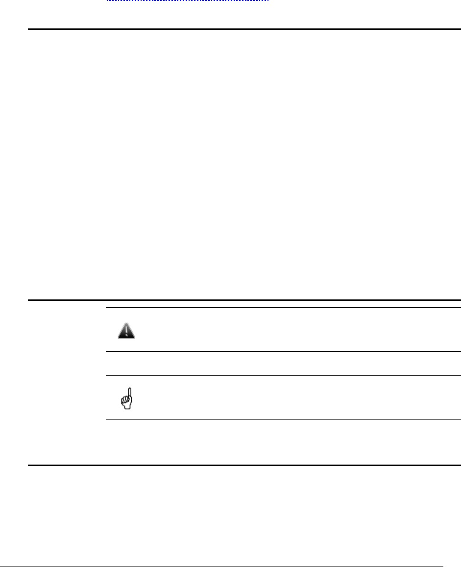
1. Power supply unit (IDU)
All outdoor equipment is equipped with indoor power supply units.
Power supply unit exterior
InfiNet Wireless R5000 Technical User Manual
Copyright © 2004-2006 by InfiNet Wireless Limited. 8
2. R5000 series
InfiNet Wireless R5000-O
Front panel
Top view
InfiNet Wireless R5000 Technical User Manual
Copyright © 2004-2006 by InfiNet Wireless Limited. 9
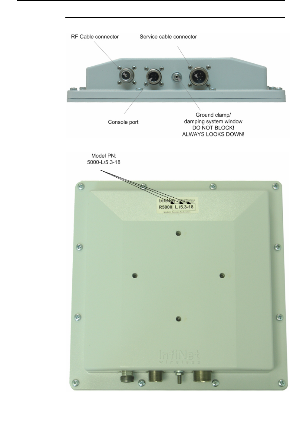
InfiNet Wireless R5000-S
Front panel
Top view
InfiNet Wireless R5000 Technical User Manual
Copyright © 2004-2006 by InfiNet Wireless Limited. 10
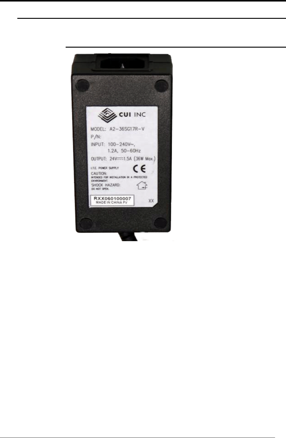
InfiNet Wireless R5000-L
Front panel
Top view

InfiNet Wireless R5000 Technical User Manual
Copyright © 2004-2006 by InfiNet Wireless Limited. 11
III.Installation procedure
1. Installation preparations
Required components and accessories
Before the installation, please make sure you have all necessary parts and
accessories:
• InfiNet Wireless Router
• Antenna
• Low loss antenna cable for the required frequency range
• Antenna pole (if necessary)
• Required grounding system
• Accessories and tools
Antenna placement
When planning an antenna placement for PTP link, in order to obtain the
maximal coverage range and best performance for the Router, one need to
consider that LOS requirements must be fulfilled for the path between two
antennas. Moreover, it is of vital importance that the certain zone that surrounds
the signal propagation path must be free from obstructions. One should
understand that the radio beam is not as thin as, for example, laser beam. Radio
beam, also called as a 1st Fresnel zone, has a profile of a rugby ball. Its exact
form and size depend upon the frequency and the signal propagation path
length.
If most of the 1st Fresnel zone is obstructed, a major part of a electromagnetic
energy will be lost which leads to a severe signal quality degradation and, as a
result, to coverage range decreasing.
Below is an incomplete list of possible obstructions on the signal propagation
path:
• Neighboring buildings
• Trees
• Bridges
• Power lines
To obtain the best results, it is necessary to perform a precise analysis of a
signal propagation path zone and possible obstructions that may cover a part of
the 1st Fresnel zone (usually the analysis is performed at the highest points of
the signal propagation path).
When planning the antenna placement for Point-to-Multipoint connections, one
must consider the necessity of a circular or sector coverage areas. In this
respect, it is not recommended to use omni-directional antennas when sector
antennas can be used.
While planning, it is strongly recommended to consult high-qualified
and experienced technicians

InfiNet Wireless R5000 Technical User Manual
Copyright © 2004-2006 by InfiNet Wireless Limited. 12
General recommendation for antennas placement are the following:
• Install antennas as high as possible over specific level. In case of flat
surface - it will be ground level, in case of vegetation and forest – it will
be tree heights, in urban environment – it will be the highest building in
the observed area (specific level definition).
• Avoid tree and vegetation along with wave propagation path, influence
of trees can increase depending on seasons (ice, dew, leaves);
• Proximity of other antennas should be avoided (at least 2 meters);
• Reflecting surfaces should be considered (building with reflective
windows, water surfaces or wet grounds);
• When installing antenna over water surface, one should tune height
bracket within 1-3 meter range variation, because it can yield signal level
variation from minimum to maximum.
• If seasonal changes influence on the signal quality, so then the most
probable reasons would be either the connectors are not protected
enough from humidity, summer vegetation or ice covered cabling and
connectors during winter.
Antenna poles usage
Antenna installation is performed on a special facility called antenna pole. The
pole is used for strong antenna tightening at the installation site. Poles might
have different modifications depending on the installation requirements.
Poles with Stretching
Usually this kind of poles are used when installing antenna on a flat surface and
permits one to raise it to a significant height for providing optimal conditions for
signal propagation.
Wall Mounted Pole
Usually these kinds of poles are used when there is no need to elevate antenna
to the rooftop and there is the possibility to mounting it on a wall. This
installation is significantly simpler than that implementation with poles. Mostly it
is used for subscriber side deployments.
Antenna Poles Requirements
Ease of antenna mounting and sufficient mechanical durability should provide
reliable fastening in conditions of high windy loads. Poles should have round
profile for ease of azimuth adjustment. Typical pole diameter is 30 to 50 mm.
Grounding
Antenna should be placed on the mast on the level that is at least 1 meter lower
than a mast’s top. In this case it is of big probability that the lightning strikes the
mast and not the antenna. The mast is to be grounded on the grounding contour
according to your local standards. When the lightning strikes the antenna, the
current goes through the coaxial cable which grounds ODU clamp with the mast
– the mast is grounded via the grounding contour. The direct lightning strike to
the STP service cable (ODU-IDU) is partially terminated on the grounded IDU
case. Partial termination means that the direct lightning strike will probably
destroy an STP cable. The service cable pickups from the electromagnetic

InfiNet Wireless R5000 Technical User Manual
Copyright © 2004-2006 by InfiNet Wireless Limited. 13
impulses are terminated on the IDU case by the winding shield, and further – on
the grounding contour. The data & power wires pickups on the top are
terminated via ODU protection scheme; on the bottom – via IDU protection
scheme (discharger and additional air gap). ODU and IDU grounding contours
are connected with 100 kOhm resistor, and that provides no static charge
accumulation on the ODU case if there are some problems with its connection to
the grounding contour.
Antenna pole, tower, ODU and lightning arrestor should be connected
to the first common grounding contour. Cable thickness should be no
less than 10AWG using corrosion-steady connectors. It is highly
recommended to entrust grounding contour development to the
skilled personnel. IDU should be grounded to the same contour as
customer LAN, having the second common grounding contour.
Antenna should be grounded
Antenna alignment
To obtain maximal system performance antennas must be precisely aligned one
towards another according to LOS requirements. General recommendations for
antenna alignment are the following:
• Align antennas using optical equipment (binoculars, spyglass)
accompanied by mobile phone actions coordination
• Use GPS receiver and area map
• Use build-in InfiNet Wireless Router features. These features allow
evaluating current channel/signal quality and perform precise antenna
alignment
Omni-directional and sector antennas have a wide radiation diagram width, thus
usually they either do not require a very precise alignment or it is just not
necessary due to radio link requirements.
Antenna polarization must be taken into consideration while installation. In most
cases omni-directional and sector antennas have a vertical polarization.
Directional antennas can be installed either with vertical or horizontal
polarization. Please check a corresponding labeling on the antenna and address
to the antenna technical documentation.
Sound indication usage
Sound indication is performed in channel testing mode (RMA command with
Autotest option). The device is intended to be used while preliminary link
establishing and antenna alignment procedure in order to obtain the maximum
signal level from the remote side.
When having AudioMonitor plugged into the console port of the device with
headphones plugged in, the sound signals will be sent to the headphones. The
AudioMonitor or the console cable must be plugged in when the device is
powered off.
No return packets state on the testing device input (no link) with described
testing mode turned on is indicated by seldom tones in the headphones.
If there is a link established, the signal level is indicated by the set of clicks. The
higher the signal level, the higher is the frequency of the clicks and their number
in the set. The durability of the set and the interval between the sets is always
the same and has a value of 2 and 0.5 seconds correspondingly. The indication
cycle always corresponds with a PREVIOUS measurement cycle. That means that
the sound indication has a delay of 2.5 seconds.
The maximum signal level (16) is indicated by a permanent tone.
Steps to be taken in WANFlex OS:

InfiNet Wireless R5000 Technical User Manual
Copyright © 2004-2006 by InfiNet Wireless Limited. 14
• type: "rma <interface_name> autotest <MAC address> mcast
• config save
• restart the device
• plug the monitor to the console and listen
Usage algorithm:
• Fix the antenna
• Skip one indication cycle
• Listen to the sound indication
• Align the antenna and then fix the antenna again
• Skip the indication cycle
• Listen to the sound indication
• … etc
Precaution measures
Before you start the installation please read this section very carefully.
Antennas are installed on the roof tops or on the building walls. This work must
be accomplished only by personnel having special skills and experience in this
area.
Antennas and cables are electric conductors. Incidental electrostatic strikes may
occur during the system installation. This can lead to equipment damaging or
may hurt the personnel. While installing or changing the elements of the
antenna-fider system one should make sure that open metal parts are
temporarily grounded.
Do not install the antenna close to the electric power lines. Antenna and antenna
pole have to be installed in such a way that while their assembling,
disassembling and repairing they did not have any contact with power lines.
Basic precaution measures that must be fulfilled during the installation are the
following:
• Do not stay on the roof top in windy or rainy weather, during the
thunderstorm or when the working zone is covered with snow or ice
• Do not touch the antennas, antenna poles, cables and lighting arrestors
during the thunderstorm
• Antenna placement should not be close to electric or telephone lines.
Safe distance is a distance that is a sum of the two antenna poles
heights and antenna height
• Antenna cable must be grounded at all times (not relevant for 5000-M
modifications)
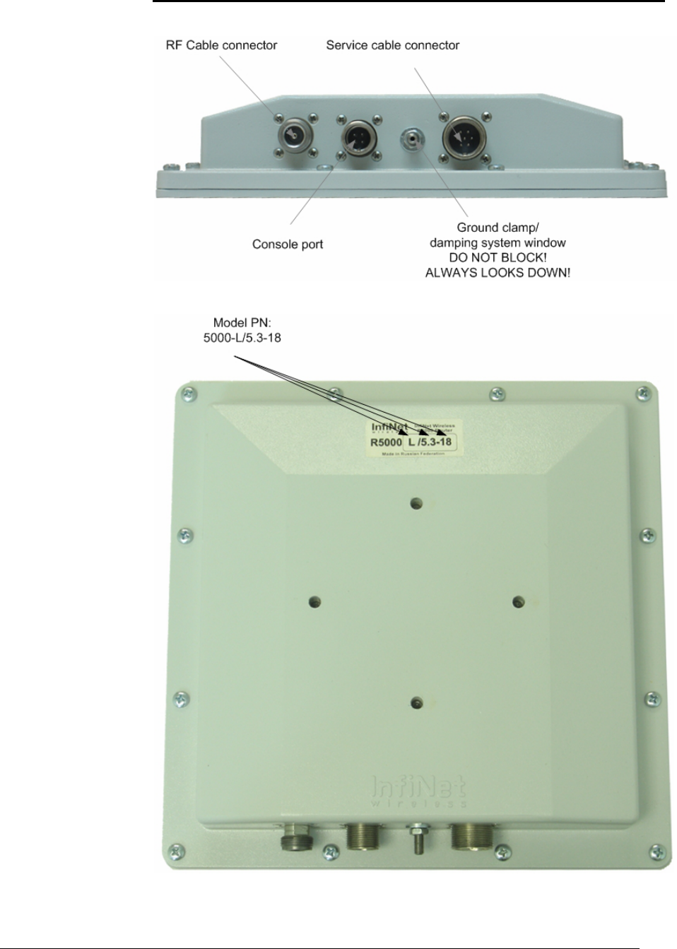
Service cable soldering procedure
The following instruction shows the connector soldering procedure
InfiNet Wireless R5000 Technical User Manual
Copyright © 2004-2006 by InfiNet Wireless Limited. 15
Step 1. Peel STP cable as shown
Step 2. Use outdoor unit to fix the
connector for further faster
disassembling
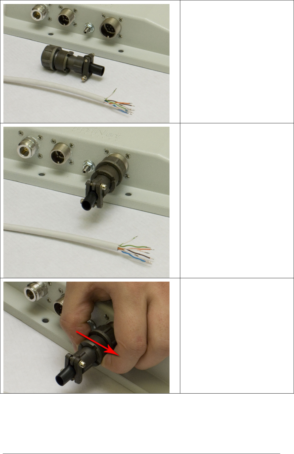
Step 3. To disassemble the connector
detach its bottom part by turning it
clockwise as shown
InfiNet Wireless R5000 Technical User Manual
Copyright © 2004-2006 by InfiNet Wireless Limited. 16
Step 4. Disassembled connector is
shown on the picture
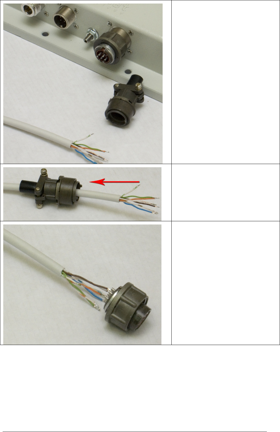
Step 5. Insert the cable into the
bottom part of the connector
Step 6. Solder the top side of the
connector according to the soldering
scheme. Unscrew the top side of the
connector from the unit
InfiNet Wireless R5000 Technical User Manual
Copyright © 2004-2006 by InfiNet Wireless Limited. 17
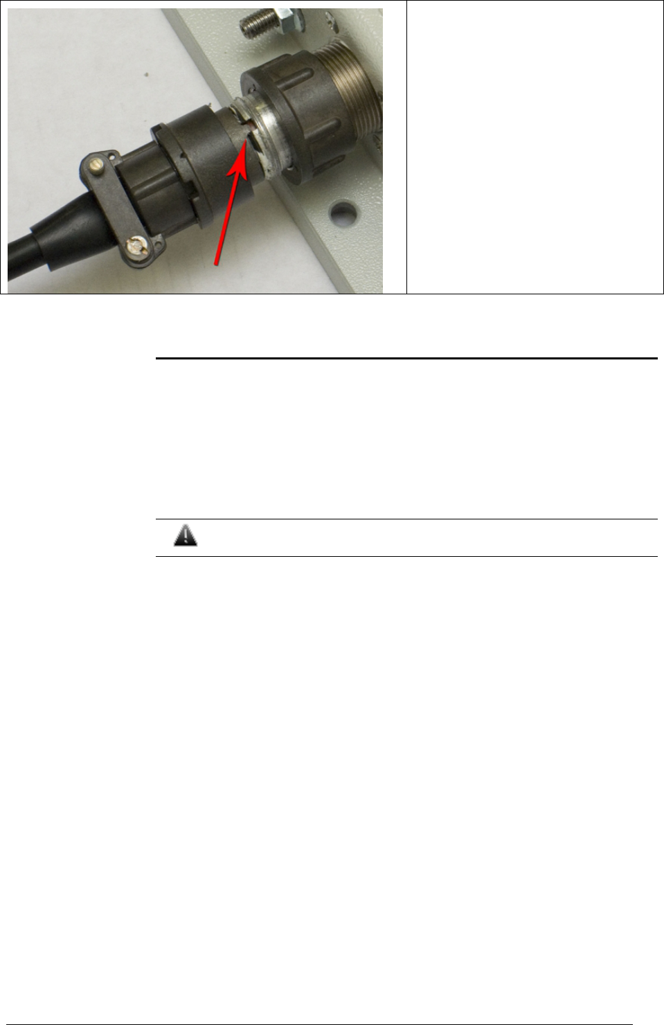
Step 7. Using outdoor unit as a holder
assemble the connector
Connectors hermetic sealing
A big number of problems with link signal quality in case of outdoor installations
result from RF cable and connectors corrosion. In order to avoid these problems
it is necessary to isolate all the connections that are situated outdoors. One
needs to use either thermal shrinkage with gel stuff or special waterproof tape.
Once the antenna alignment is not complete it is not recommended to perform
isolating. This method prevents you to remove the isolation when there is a need
to reallocate the antenna or the cable. The isolation with thermal shrinkage
usage is performed with a special fan.
Obey all precaution measures while using the fan as it is written in its
manual
The isolation using the waterproof tape is performed by its winding with
intersection around the connection.
Please keep in mind the following recommendations:
• Clean all the surfaces to be isolated and keep them free from the dust
and water
• Isolating material must cover the whole connector and the cable with a
gap of at least 2-3 cm from the connection place
• Isolating material must cover the surfaces as tight as possible
To protect the isolation material from the sun rays, it is recommended to cover it
with vinyl isolation tape.
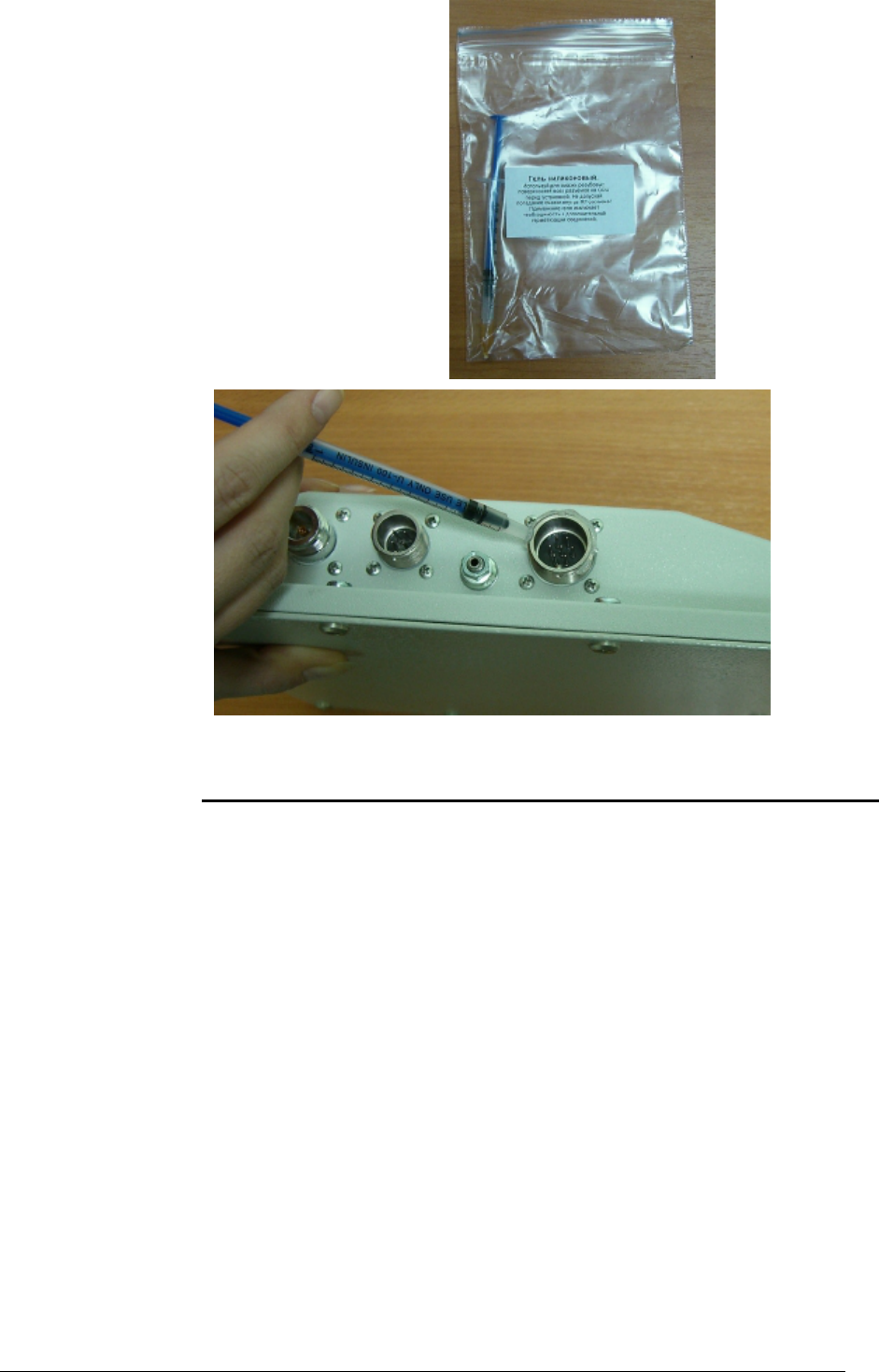
From March 2006 all units are staffed with a silicon gel which is used for a
reliable outdoor connectors sealing. With gel usage no additional sealing is
required. Even if connection was disassembled afterwards no additional gel is
required. Please see the photos below to learn who gel is put onto the
connector.
InfiNet Wireless R5000 Technical User Manual
Copyright © 2004-2006 by InfiNet Wireless Limited. 18
Tools to be available at the installation site
1. Screwdrivers set
2. Pliers
3. Soldering iron 40 W
4. Spanners set
5. Connectors isolating set
• Raw rubber
• Thermal shrinkage tube
• Scissors
• Fan
• Mantling gun
6. Additional equipment
• GPS receiver or area map (with compass and alidade)
• Big zoom binoculars
InfiNet Wireless R5000 Technical User Manual
Copyright © 2004-2006 by InfiNet Wireless Limited. 19
2. InfiNet Wireless R5000-L and InfiNet Wireless R5000-O
Installation guidelines
1. Unpack the equipment
2. Check items integrity
3. Prepare RF-cables of the
required length. For 5GHz
devices the recommended
maximal RF cable length is
1 meter.
4. Install and isolate the
connectors on the RF cable
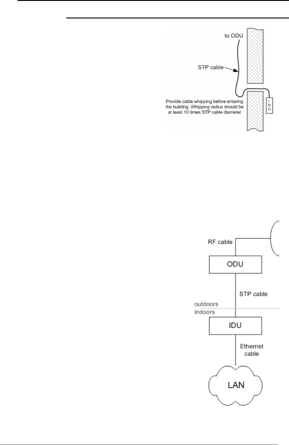
5. Determine the STP cable
length that is used to
connect IDU and ODU. The
total cable length between
LAN (behind IDU) and ODU should not be longer than 100 meters.
6. Install (solder) connector for ODU side on the STP cable and isolate it
7. Lay the STP cable “from top to bottom” – from ODU to IDU
8. After the STP cable has been laid, use distribution box to switch from STP
cable to UTP cable with RJ-45 connectors.
9. Install ODU on the mounting bracket connectors down and tighten it
10. Connect the ODU-IDU cable to the ODU
11. Isolate the ODU connector joint place
12. Once the antenna and antenna pole are
installed they must be grounded via
lightning protection grounding contour.
Antenna’s position must be lower than
the highest antenna pole point at least
by 2 antenna heights. If antenna is NOT
DC-shorted (see antenna technical
documentation), the additional lightning
arrestor must be used which is placed
between ODU and antenna and is
grounded to the antenna pole grounding
contour.
13. Connect RF cable to the antenna. Twist
the connector tightly
14. Connect RF cable to the ODU previously
having touched RF cable connector case
with ODU connector case
15. Isolate RF connectors from both sides
(ODU and antenna)
16. Connect the UTP cable to IDU
17. Provide grounding for IDU
18. Connect Ethernet cable to IDU
19. Provide power supply for IDU
20. Connect to the Router using Telnet protocol
InfiNet Wireless R5000 Technical User Manual
Copyright © 2004-2006 by InfiNet Wireless Limited. 20
It is extremely important to install ODU connectors down!
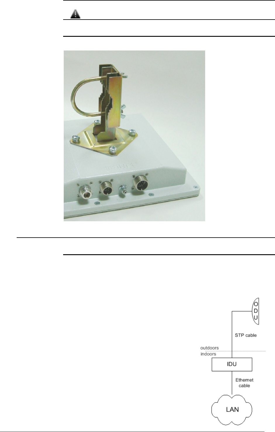
Wall mounting
Assembled mounting kit is shown on the picture below.
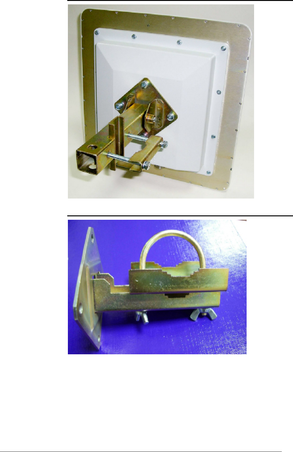
3. InfiNet Wireless R5000-S
Installation guidelines
1. Unpack the equipment
2. Check items integrity
3. Determine the STP cable length that is used to connect IDU and ODU. The
total cable length between LAN (behind IDU)
and ODU should not be longer than 100
meters.
4. Install (solder) connector for ODU on the STP
cable and isolate it
5. Lay the STP cable “from top to bottom” – from
ODU to IDU
6. After the STP cable has been laid, use
distribution box to switch from STP cable to
UTP cable with RJ-45 connectors.
7. Install ODU on the mounting bracket
according to the direction required for the link.
Do not tight it too hard unless the antenna
alignment is not complete. Install ODU
connectors down.
8. Connect the ODU-IDU cable to the ODU
InfiNet Wireless R5000 Technical User Manual
Copyright © 2004-2006 by InfiNet Wireless Limited. 21
9. Isolate the ODU connector joint place
10. Once the ODU and antenna pole are installed they must be grounded via
lightning protection grounding contour. ODU position must be lower than the
highest antenna pole point at least by 2 ODU heights
11. Connect the UTP cable to IDU
12. Provide grounding for IDU
13. Connect Ethernet cable to IDU
14. Provide power supply for IDU
15. Connect to the Router using
Telnet protocol
It is extremely important to install ODU connectors down!
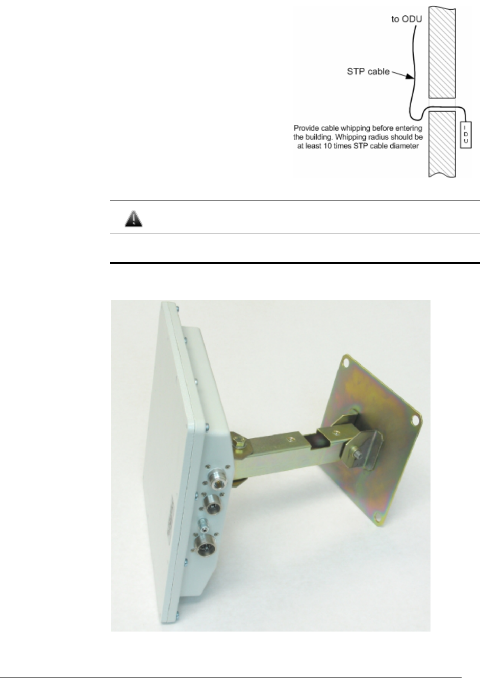
Wall mounting kit assembling
Attention! By default, the mounting kit for R5000-S does NOT contain a
plate for wall mounting – it should be ordered separately.
InfiNet Wireless R5000 Technical User Manual
Copyright © 2004-2006 by InfiNet Wireless Limited. 22
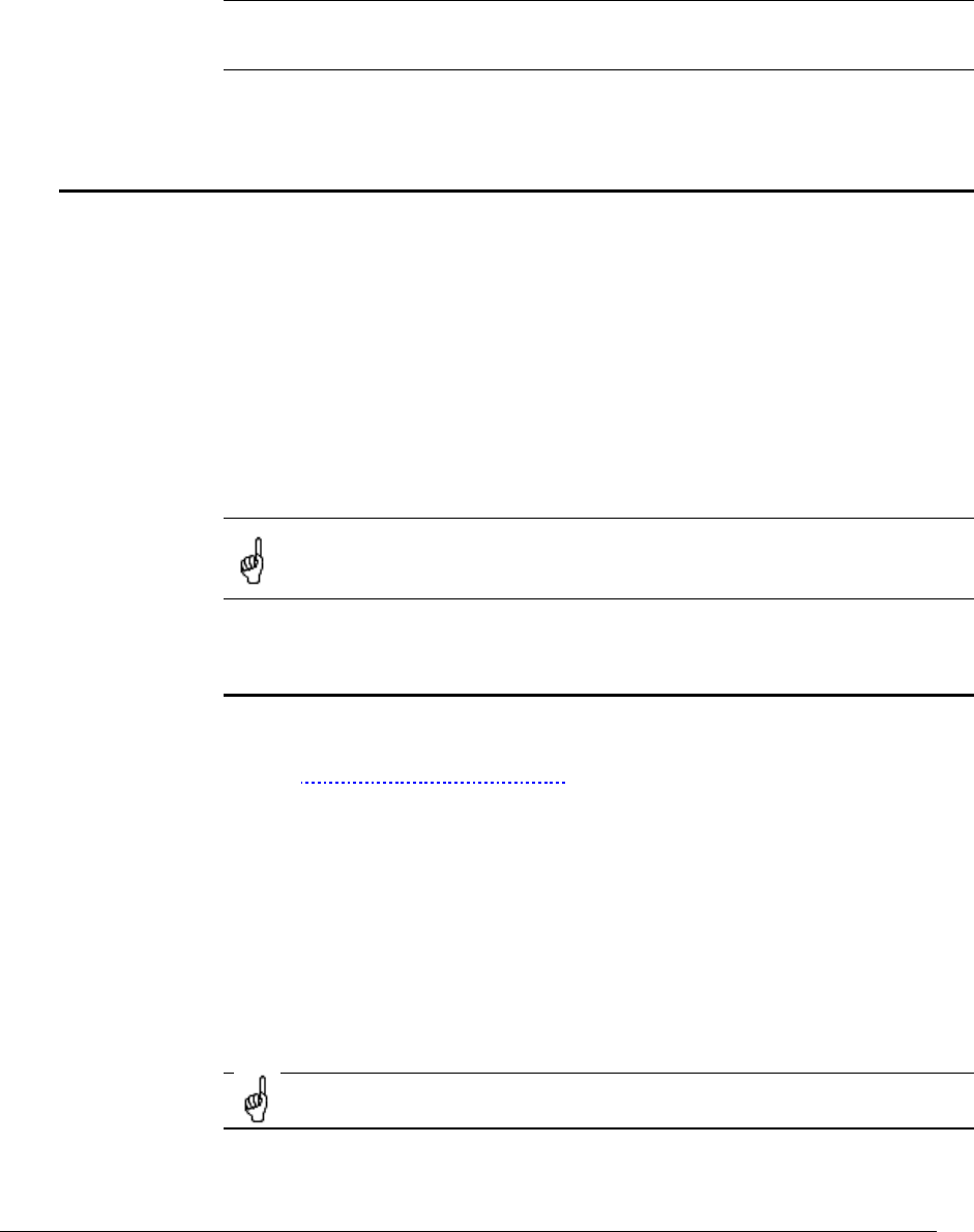
Pole mounting kit assembling
Low diameter pole mounting kit assembling

InfiNet Wireless R5000 Technical User Manual
Copyright © 2004-2006 by InfiNet Wireless Limited. 23
IV. Device configuration instructions
1. Initial settings configuration procedure
Before starting new device, one should perform initial configuration. The
configuration can be performed either using serial console port or using Telnet
protocol. In order to configure the device using Console port, follow the
instructions below:
• Device should be connected with host serial interface, using InfiNet
Console cable
• Start any terminal emulation software (e.g. Hyper Terminal)
• Set serial interface properties to 38400 baud rate, 8 bit, 1 stop bit, parity
off, flow control disabled
• Enable emulation mode ANSI or VT100, keyboard VT100
To connect using Telnet protocol from the wired LAN run Telnet with 10.10.10.1
IP-address that is configured for the Ethernet interface of the device by default.
If all above procedures are completed correctly, you will see the WanFlex OS
prompt:
Login:
Every new device has no initial login and password settings, so you can use any
non-zero length login and password to enter the device:
Login: root
Password: 1234
After default authorization there will be standard console prompt:
console>
Now the device is ready for the initial configuration procedure. The most relevant
thing to be done at this phase is to define device name/user/password.
system name Test Base Station
system user root
system password qwerty
Part of commands in bold must be typed in CLI (Command Line
Interface). The rest of the command name is optional and can be
skipped while typing.
Since this is made ONLY specified username and password can be used to access
the device. DO NOT FORGET THESE PARAMETERS.
2. Router interfaces
The Router has several physical and logical interfaces:
• lo0 - loopback interface, used for system interaction needs
• null0 – logical interface, can be used for auxiliary addresses assignation
(for NAT module, for example); for routes aggregation for RIP protocol.
Addresses (subnet) are announced to the network but every packet
transmitted through this interface is destroyed
• eth0 - Ethernet 10/100 Mbit interface

InfiNet Wireless R5000 Technical User Manual
Copyright © 2004-2006 by InfiNet Wireless Limited. 24
• rf3.0, rf4.0 - radio interface. See device’s labeling it learn your radio
interface name
• pppX – point-to-point interfaces
• tunX - interfaces used for IPIP tunnels building
• vlanX – interfaces supporting VLAN 802.1q tagging
All configures interfaces of the router can be reviewed using the following
command:
ifconfig -a
3. Command line interface (CLI)
For device’s management and configuration a Unix-like command line language
is used. Every command starts having the power right after Enter key is pressed.
However, each command lifetime duration is limited within one configuration
session. In order to save a current configuration “config save” command is
used.
Several commands can be grouped in one line using “;” character. If a wrong-
syntax line is met in the group, the rest of the string is checked anyway and the
wrong command is ignored. Command name can be shortened unless the
ambiguity occurs.
If your terminal supports VT100 or ANSI standard you can move around the list
of recently executed commands using cursor keys. Numbered list of these
commands can be reviewed by “!h” command. Any command from this list can
be available using “!<NUMBER>” command. TAB key performs substring
search of recently executed commands.
Ctrl/R combination refreshes the command string if its content was disturbed by
system messages.
The command executed with no arguments prints a short hint about its keys,
parameters and syntax.
Context help can be obtained by printing “?” in any position of the line.
4. Lost password recovery
Starting from WANFlex OS 3.32 firmware version, the password can be
recovered remotely. The procedure is the following:
1. Locate your device’s serial number
2. Send this SN to the InfiNet Wireless Technical Support
3. You will be given a special key
4. Enter the device and use SN as a login and received key as a password
5. Reconfigure the username and password
5. Configuration manipulations
Printing and saving your configuration
You c
an easily review your current device’s configuration by executing
“config show” command. The output of the command is sorted by the
configuration sections (e.g. “System parameters”, “Interfaces configuration” etc).
You can review some particular parts of the configuration specifying the part of
the configuration you want to see.

InfiNet Wireless R5000 Technical User Manual
Copyright © 2004-2006 by InfiNet Wireless Limited. 25
Example:
config show ifc
This command will print the interfaces configuration. You can specify several
parts of the configuration separating them with a space bar.
Example:
config show rip nat
In order to save your configuration “config save” command is used. It saves the
current system configuration in the router's flash memory for subsequent
permanent use. All modifications to the system parameters, if not saved by this
command, are valid only during the current session (until the system reset
occurs).
Import/export
Export/import of the device’s configuration is performed using “config export”
and “config import” commands correspondingly. “Config export” saves the
router configuration on a remote server and “config import” reloads it from a
remote server. The information is transferred using FTP.
Example:
config export user:secret@192.168.1.1/var/conf/test.cfg
“Config import” command writes the uploaded file directly into the Flash
memory without changing the active configuration in RAM. In order to make a
new configuration active, right after “config import” command implementation
finishes the device should be rebooted. If “config save” command is run before
rebooting, Flash memory is overwritten by the copy of the active configuration.
This action will erase the uploaded configuration file.
New firmware uploading
The latest firmware version can be downloaded from
www.infinetwireless.com web-site “Support/Downloads” section.
Command “flashnet” uploads specified firmware version to the Router.
Download is performed using FTP and FTP server should be installed somewhere
in the network or on a local host from where download being performed.
File name is a full path including IP address of FTP server:
flashnet get upgrade@192.168.1.1/conf/infinet/infinet_new.bin
Where 192.168.1.1 is IP-address of FTP server and
.../conf/infinet/infinet_new.bin is a full path to firmware version.
The download process has two phases:
• File uploading into RAM of InfiNet device.
• Programming InfiNet device flash memory from RAM firmware image. This
phase is indicated by “O.O.O.O.O.O…” sequence.
Do not interrupt this process, otherwise device will be brought into
invalid state and it recovery will be possible only at manufacturer
premises.
During installation process all system events should be observed in the system
journal (command “sys log”).

InfiNet Wireless R5000 Technical User Manual
Copyright © 2004-2006 by InfiNet Wireless Limited. 26
6. IP address formats
Many commands of the operating system require specification of IP addresses.
In OS WANFleX, the IP-addressees may be specified in traditional numeric
format. Optionally, the mask may be specified either by its bit length (the
specified number of leading bits in the mask are set to 1, the remaining bits are
reset to 0) or numeric value. The IP address 0/0 denotes all possible IP
addresses.
Therefore, the possible formats to specify IP-addresses are:
nn.nn.nn.nn (no mask is used)
nn.nn.nn.nn/N (N is the bit length of the mask)
nn.nn.nn.nn:xxx.xxx.xxx.xxx (xxx.xxx.xxx.xxx is the numerical value of the
mask)
Example:
The 192.168.9.0/24 address describes the network address 192.168.9.0 and the
mask with leading 24 bits on.
The same set of addresses may be denoted as 192.168.9.0:255.255.255.0.
7. Ethernet interface configuration
In the most basic form Ethernet interface can be configured as follows:
ifconfig eth0 1.1.1.1/24 up
UP flag means than the interface is turned to UP state.
Also you can specify the following parameters for the Ethernet interface:
• Media type. By default media type is selected automatically (media
auto parameter).
• Assign aliases to the Ethernet interface (alias key word)
Full information about interfaces configuration can be reviewed in OS WanFlex
User Guide – ifconfig command.
8. Radio interface configuration
Radio interface configuration is performed using “rfconfig” command. In its
most basic form one need to configure the following parameters of the radio
interface:
• Frequency (freq parameter) in MHz. For example, 5260.
• Bit-rate (bitr parameter). Bit transfer rate in kBits/sec.
• System identifier (SID parameter). A hexadecimal number in the range
of 1H to FFFFFFH. All routers that are supposed to see each other on the
same radio link must have the same identifier.
Radio interface state is not saved in the configuration. That means
that if you put radio interface to the down state after rebooting it will
be in the up state.
To learn your device’s radio module capabilities type the command:
rfconfig <IF-NAME> capabilitites
<IF-NAME> - radio interface name. Can be read on the device’s labeling located
on the case.

InfiNet Wireless R5000 Technical User Manual
Copyright © 2004-2006 by InfiNet Wireless Limited. 27
This command outputs the following information:
MAC silicon revision:
5.6
PHY silicon revision:
4.1
5GHz analog
silicon revision:
1.7
Power levels (mW):
6, 8, 16, 32, 63
MAC address:
00028AE1D787
Frequency list:
5260, 5280, 5300, 5320, 5340.
Bitrate list: 6000, 9000, 12000, 18000, 24000, 36000,
48000, 54000
Radio interface configuration is performed using “rfconfig” command.
Example:
rfconfig rf4.0 freq 5260 bitr 24000 sid 01010101
Additional important parameters and settings for the radio interface:
• rf4.0 – radio interface name in this case. In order to obtain
radiointerface name either see the ODU/Router labeling or execute
“ifc -a” command.
• pwr – transmitting power selection. Available power levels can be
obtained using “capabilities” parameter as shown above
• burst – enables burst mode. BURST protocol means grouping several
short packets with the same destination address on a radio link into
larger packets, thus cardinally decreasing the response time for
applications generating streams of short packets. Burst enabling relates
to a radio interface as a whole, and means only that you want to use
this mode in this device; but the BURST protocol can only work for
destinations where it is also enabled at the other end, and only if the
RMA protocol is used at both sides.
Burst enabling does not induce any changes in the work of other devices
in the network. To disable “burst” mode use “-burst” parameter in
“rfconfig” command.
• distance: this parameter is used to set the exact distance value
between two devices (in kilometers). This parameter changes time
values for some delays and time-outs of 802.11a/b/g protocol thus
making possible to work on longer distances with smooth adjustment.
There are several ways to manage this parameter:
o if you set an exact value, this value is used no matter what the
connection method is used
o If the CPE has auto value instead of a number (by default), the
CPE will configure its parameters using Base Station commands.
It is enough to set a numeric value on a Base Station (the
distance to the remotest CPE); all other CPEs will automatically
adjust their work. While configuration showing, there might be
the current distance value after auto parameter: auto (XX)
o when knowing exact device's geographical coordinates (e.g.
using GPS) you can specify their values in “sys gpsxy”
command and distance parameter set as auto on all devices
including the Base Station. In this case devices will automatically
adjust their settings selecting an optimal value for the distance
parameter. Base Station will calculate a distance to the remotest
InfiNet Wireless R5000 Technical User Manual
Copyright © 2004-2006 by InfiNet Wireless Limited. 28
subscriber, and subscriber will calculate a distance to the base
station. If the CPE has a link coordinates information it will use
this information, otherwise it will use the distance parameter
value got from the base station.
o If distance parameter is set to 0 radio module will use default
settings.
o pwrctl – automatic transmitting power control mode. In this
mode the output power is set up automatically within the values
available for the radio module. Used for CPE only.
Example:
rfconfig rf4.0 freq 5260 bitr 36000 sid 10203040 burst
rfconfig rf4.0 pwr 63 ant RIGHT distance 0
ANT parameter is specified on the label on the device’s case. The default setting
corresponds with a labeled value.
9. Routed Multiple Access protocol configuration
Every InfiNet Wireless Router can be configured as a subscriber unit or as a base
station. Each link between a base station and a subscriber unit is described as a
PTP connection (or a subnetwork consisting of two units).
From external networks each subscriber unit will be seen as a subnetwork with
the mask length of 30, and the information on attainability of this subnetwork
and of all subnetworks connected to the subscriber unit will be spread by all base
stations, where this subscriber unit is described.
The RMA protocol provides a mechanism enabling to direct routing information
relating to a subscriber unit in such a way that at any moment of time it comes
out only from that particular base station, to which this subscriber unit is actually
connected.
It is HIGHLY recommended to use this protocol at all times even in
PTP topology. RMA protocol does NOT differentiate between PTP and
PTM topologies in both configuration ways and algorithms it uses.
The routing information can be processed using any available routing protocol.
Basic mechanisms
• RAPS database (Remote Access Permission Service) is common for all
subscribers. For detailed description please address to our web-site
www.infinetwireless.com “Support” section.
• Link testing protocol
• Subscribers’ registration on the Base Station with a permanent link
quality testing
• Roaming mechanism (subscriber’s movement from one station to
another) is based on the dynamic IP-routing
• Adaptive polling
• Adaptive transmit power control
• Adaptive Modulation & OFDM signaling scheme
When having RMA mode turned on, one should not configure radio
interface IP-addresses manually. See below description.

InfiNet Wireless R5000 Technical User Manual
Copyright © 2004-2006 by InfiNet Wireless Limited. 29
Base Station configuration
BS is configured by specifying all of its CPEs using “rma ab” command. The
command format looks as follows:
rma ab <IFNAME> MAC ip=MYIP [name=NAME] [options]
“Rma ab” parameters:
• IFNAME – name of the radio interface
• MAC – MAC-address of the CPE. In order to obtain this address please
use one of the following commands on the CPE:
o ifconfig –a
o rfconfig <IFNAME> capabilities
• MYIP – IP address of the connection as seen from the base station
(mask length equals 30). IP-address for the CPE radio interface is
assigned automatically
• NAME - subscriber's mnemonic name (up to 20 symbols without spaces)
• Options can be the following:
o –disable|-enable - disables and enables the RMA mechanism for
the CPE correspondingly
o -del : removes the specified parameters from the BS
configuration table
To review current BS tables containing all its subscribers use “rma ab” command.
rma ab command shows the status of all subscriber units registered on the base
station and current connection quality, as shown on the following example:
1 2 3 4 5 6 7
ab1
00028ae1d72a
NewRWR.0.1
9.9.0.1->2
11/8
A/B/P <18/36>
ab2 00028ae1d795
NewRWR.0.5
9.9.0.5
Fields description:
Field#
Description
1 System assigned device’s name. Can be used instead of a MAC-
address while configuring
2 Subscriber unit MAC address.
3 Unit mnemonic name.
4 IP-addresses: (base station)>(subscriber unit). The address of a
subscriber unit is included into the table after successful registration
of the unit.
5 Current connection quality measured in relative units from 0 to 16.
0 indicates the weakest signal quality, 16 – the strongest.
<signal level from CPE>/<signal level from BS>
6 Status field.
A – active

InfiNet Wireless R5000 Technical User Manual
Copyright © 2004-2006 by InfiNet Wireless Limited. 30
B – burst mode on
P – polling mode on
7 <transmitting speed>/<receiving speed>
CPE configuration
CPE configuration is performed using “rma bs” command. For each subscriber
one can specify several base stations at which the CPE can be registered (see
Roaming section). The command syntax looks as follows:
rma bs <IF-NAME> sid/speed[/minspeed] freq [,freq...] [-del]
When executed without parameters, the RMA BS command displays the status of
the base station selected and the current connection quality.
The command has the following parameters:
• IF-NAME - the name of a radio interface
• sid - a network identifier
• speed - requested connection speed (bitrate) in KBit/s (if autobitrate
mode is turned on, this parameter sets the highest possible speed). The
list of available speeds can be displayed by "rfconfig <IF-NAME> bitr"
command and depends on radio module type.
• Minspeed – optional parameter used in autobitrate mode. Sets the
minimal value for the speed.
• freq - the base station operating frequencies; any number of
frequencies may be specified, as a list of individual frequencies and/or of
frequency ranges f1-f2, separated by commas.
The -DEL option is used to remove the specified parameters from the subscriber
unit's configuration table.
Example of BS configuration on the CPE:
rma bs rf4.0 01010101/24000 5260, 5280
If you want this CPE to attempt to connect to another Base Station, you should
specify it in a separate line with different frequencies and/or bitrate.
“rma bs” command executed without parameters shows current registration of
the CPE on the BS.
Еxample:
rf4.0: bs (10101011/24000,5280) 00028aeb54d4 Q=155 7/6 IP=1.1.1.1
Links 13, reps 13, Q=155 Rx=18 Tx=24 burst
Here:
• rf4.0 – name of the interface
• 101010011 – SID
• 24000 – configured maximum speed (upstream to BS)
• 5280 – working frequency
• 00028aeb54d4 – MAC-address of the BS at which the registration was
performed
• Q (1st entry)– base signal quality level
• Q (2nd entry) – current signal quality level

InfiNet Wireless R5000 Technical User Manual
Copyright © 2004-2006 by InfiNet Wireless Limited. 31
• 7/6 – “signal level from the subscriber”/”signal level from the BS”.
Measured according to the relative InfiNet scale from 0 to 16 (0 – min,
16 – max)
• IP – IP-address for the radio interface from the BS side
• Links – number of testing packets sent
• Reps – number of testing packets acknowledgments received
• Rx – data rate on receiving in Mbit/sec
• Tx – data rate on transmitting in Mbit/sec
• Burst – Burst mode is turned on
Bitrate control
Traditional ways of InfiNet router's usage imply a fixed connection speed
between a base station and a subscriber. A subscriber while searching and
registering on a base station chooses an optimal mode which is available in the
configuration and afterwards does not change connection parameters even if
radio channel characteristics (signal levels, noise level) are changing. The speed
in both directions is set as it is configured on the subscriber's side. If the
conditions worsen so much that further work is impossible the connection breaks
and a new base station search runs or new work parameters are being chosen.
This way of configuration is logical when one needs to get a reliable channel with
previously known characteristics and when all radio channel parameters are
thoroughly designed.
However in some cases when there is a need in fast channel making (if it has
non-critical parameters) it is more convenient to switch to an automatic mode.
The automatic speed control mode solves this problem. In this mode every
device controls the connection parameters independently (amplitude of the
received signal, SNR on the opposite side etc) and chooses such transmitting
speed which provides necessary conditions for a reliable work with minimum
number of ARQs and losses. Speed values can be different for each direction but
it will be optimal.
If this mode is turned on at the subscriber's side the base station will turn it on
also for this particular subscriber. In this case the base station search is
performed on the minimal for the subscriber speed and then the speed is
increased to its maximum value (it can be limited by the speed specified in rma
bs command or by limitations for the specific device model). If autobitrate mode
is turned on at the base station all subscriber devices that work with it will
automatically switch to this mode.
The speed ranges for the autobitrate algorithm are specified in CPE
configuration by specifying speed and minspeed parameters.
In order to turn this mode on (either on BS or CPE), type:
rma <IF-NAME> autobitrate
In order to turn this mode off (either on BS or CPE), type:
rma <IF-NAME> -autobitrate
Roaming
Roaming means that for each CPE several base stations with which it can
potentially interact can be specified. If there are several BS configured for the
CPE, it will measure signal quality level with each of those BS and choose the BS
with the best integral characteristic. In order for the CPE to have a roaming
feature one should:

InfiNet Wireless R5000 Technical User Manual
Copyright © 2004-2006 by InfiNet Wireless Limited. 32
• Specify using “rma bs” command all BS that CPE can potentially work
with
• On each BS that is specified in CPE’s configuration one need to configure
the CPE
Subscriber’s LAN switching from one base station to another takes place with no
LAN Ethernet interface IP-addresses changing.
Router’s configuration rebuilding takes not more than 15 seconds when the base
station changing is performed.
IP-routing is used as a roaming mechanism and this feature allows subscriber’s
relocation within the whole network and switching between different base
stations.
Polling
The WMA/CD (polling) regime is a method of accessing common radio channel
under base station control, which means a centralized distribution of
transmission authorization markers by a base station to subscriber units. This
regime greatly improves operational stability and throughput of base stations
under conditions of heavy load and signal level misbalance between different
subscriber units. It is particularly useful when subscriber units are at long range
from a base station and not in the direct visibility of each other, so that they
cannot avoid mutual collisions in the radio channel by listening each other's
transmission. The polling regime makes it possible to establish reliable
communication between subscribers when the ordinary CSMA/CA wireless access
method does not work at all.
Despite a slight decrease in the maximum transmission speed, the polling regime
substantially increases the total throughput of a base station and provides for its
fair distribution between subscriber units.
Among the drawbacks of wireless polling method one can mention comparatively
greater initial delay and greater response delay variations for series of short
packets, which is adversely affecting such applications as telemetry and on-line
games.
The polling regime is enabled on the base station only. Configuration of
subscriber units needs not to be modified. All those units, however, shall have
RMA protocol enabled.
A base station with polling regime enabled may simultaneously serve both polling
and non-polling subscriber units; presence of non-polling units (dumb units,
relay-points which combine both BS and CPE configuration), however,
substantially reduces the whole system's effectiveness.
To turn polling regime on the BS, type:
rma <IF-NAME> poll
To turn polling regime off, type:
rma <IF-NAME> -poll
Polling mode is recommended to be used with RMA protocol as it
determines the radio environment and makes it predictable. The
competitive results of CSMA/CA and polling protocols are presented
on our web-site
Polling mode can significantly increase a ping round trip time. In this
case this time is not a measure of a link quality.

InfiNet Wireless R5000 Technical User Manual
Copyright © 2004-2006 by InfiNet Wireless Limited. 33
Link Test & Control
A Base Station performs a permanent link testing with a subscriber. Each testing
is accompanied by subscriber’s information update in the Base Station’s tables.
This mechanism provides a system operator with comprehensive data concerning
registered subscribers and links quality without any additional tests launching.
RMA usage
The following procedure is recommended for RMA protocol configuration:
• Define which of the network components act as a BS and which are CPEs
• Configure all CPEs on the BS using “rma ab” command
• Configure BS on each CPE using “rma bs” command
• Run RMA on each device using “rma start” command. RMA mode can
be disabled using “rma stop” command
• Enable polling mode on the BS
• Define which links are not stable at the configured speeds and try using
autobitrate mode either for some specific CPEs or for the whole cell

InfiNet Wireless R5000 Technical User Manual
Copyright © 2004-2006 by InfiNet Wireless Limited. 34
V. Link Configuring
1. Preliminary decisions
Speed selection
Basic recommendations for the device’s speed selection are the following:
• The overall performance of the channel built using 54 Mbps devices is
just a little bit higher than for 48 Mbps devices. However, the noise
immunity for 54 Mbps is less than for 48 Mbps. So, the recommendation
is to configure your devices for 48 Mbps speed instead of 54 Mbps
• BS downstream speed to CPE can be configured as high as it is possible.
Upstream speed from CPE to BS should not exceed 24 Mbps. This kind of
asymmetry leads to less expenses to create a required attenuation
between BS sectors – subscriber’s equipment costs less and the optimal
price/performance parameter value is obtained
• By effective antenna selection for the subscriber units, one should set up
equal speeds for all subscribers regardless their individual performance
requirements
• In order to obtain a stable work mode for the whole network set up
Autobitrate mode with optimal range of available speeds provided
Examples of typical network equipment selection:
1. Network with upstream traffic prevailing (e.g. video surveillance systems)
• Base Station: 5000-O 5.8 24P200. Sector antenna gain: 17 dB
• Nearest subscribers (e.g. 3 km coverage area): 5000-O 5.8 24
with 19 dB directional antenna
• Remote subscribers (e.g. 9 km coverage area): 5000-O 5.8
24P200 with 29 dB directional antenna
• Bottom value for the speed: 12 Mbps
• This solution provides with the performance of not less than 8
Mbps real throughput
2. Network with downstream traffic prevailing (e.g. ISP networks)
• Base Station: 5000-O 5.8 36P300. Sector antenna gain: 17 dB
• Nearest subscribers (e.g. 6 km coverage area): 5000-O 5.8 18
with 19 dB directional antenna
• Remote subscribers (e.g. 12 km coverage area): 5000-O 5.8 18
with 29 dB directional antenna
• Bottom value for the speed: 6 Mbps
• This solution provides with the performance of not less than 4
Mbps of real throughput for upstream traffic and 8 Mbps for
downstream traffic with maximal coverage area
3. Network with downstream traffic prevailing (e.g. ISP with different
services)
• Base Station: 5000-O 5.8 36P3000. Sector antenna gain 17 dB
• Nearest subscribers (e.g. 2.5 km coverage area): 5000-O 5.8 19
dB directional antenna
• Remote subscribes (e.g. 5 km coverage area): 5000-O 18 with
29 dB directional antenna

InfiNet Wireless R5000 Technical User Manual
Copyright © 2004-2006 by InfiNet Wireless Limited. 35
• Bottom value for the speed: 12 Mbps
• This solution provides with the performance of not less than 8
Mbps of real throughput for upstream traffic and 14 Mbps for
downstream traffic with maximal coverage area
Frequency planning for multi-sectored Base Stations
Base Stations with six sectors deliver the maximal performance by providing with
sector reciprocal reservation and best price/performance parameter value. When
having an optimal frequency gap of 40 MHz between adjacent sectors of the BS,
the following schemes are recommended to be configured (e.g. having 5
available in configuration frequencies F1, F2 … F5):
• F1, F3, F5, F1, F3, F5
• F1, F3, F1, F3, F1, F3
Transmitting power selection
High output power provides with a maximal connection performance. Power
decreasing is logical when the maximal speed is already reached and there are
no repeats. In this case an excessive output power can decrease the system
parameters. When having no built-in or external amplifiers one can try to install
the automatic power control for the subscriber.
Fade margin calculator
Fade Margin Calculator is used for estimating the link energetic parameters and
for upstream/downstream speeds prognosis. The calculator is available at
www.infinetwireless.com web-site in the Support section.
The procedure for the Calculator usage is the following:
1. Specify “Distance” and “Frequency” parameters of the link
2. Specify “Antenna Gain” for Unit №1 and for Unit №2
3. Specify “Cable Attenuation” per 1 meter cable length. For example, for 2.4
GHz devices - 0.24 dB, for 5 GHz – 0.4 dB. Depends upon used cables.
4. Specify “Output power” in milliwatts
5. Specify “Receiver sensitivity”. In order to do that, please think of the
desired/predicted speed on the link and refer to the tables below the
Calculator. For Unit №1 – predict UPSTREAM speed. For Unit №2 – predict
DOWNSTREAM speed
6. If you use external amplifiers, fill out “Amplifier” section(s)
7. Press “Recalculate” button
8. Perform the following actions:
• For UPSTREAM speed prognosis use “Signal level by InfiNet scale”
parameter for Unit №1. Subtract “Sinking Offset” parameter
provided below. Search the calculated value in “Minimal InfiNet scale
level required for maximal throughput” in the tables below. If the
value matches with the predicted speed, the link works with selected
parameters. If not, please select another speed and go back to Step
6
• For DOWNSTREAM speed prognosis use “Signal level by InfiNet
scale” parameter for Unit №2. Subtract “Sinking Offset” parameter
provided below. Search the calculated value in “Minimal InfiNet scale
level required for maximal throughput” in the tables below. If the
value matches with the predicted speed, the link works with selected

InfiNet Wireless R5000 Technical User Manual
Copyright © 2004-2006 by InfiNet Wireless Limited. 36
parameters. If not, please select another speed and go back to Step
6
In order to obtain speed range calculation for the link (for 5GHz devices only),
please refer to “Speed range calculator”.
Landscape details and signal propagation path obstructions are not
taken into account in the calculator.
Speed range calculator
Speed range calculator is used for Speed/Coverage parameters calculation for
the link. The Calculator is available at the www.infinetwireless.com web-site
in the Support section.
The Calculator works for 5GHz devices only
The procedure for the Calculator usage is the following:
1. Specify “Distance” and “Frequency” parameters of the link
2. Specify “Antenna Gain” for “Base Station” and “CPE”
3. Specify “Cable Attenuation” per 1 meter cable length
4. Specify “Output power” in milliwatts
5. If you use external amplifiers, fill out “Amplifier” section(s)
6. Press “Calculate” button
The results are presented at the right side of the table. “Best” and “worst” values
for bitrates both for BS and CPE act as recommendations only when planning
the network. The worst value implies lower energetic parameters for the clients
that are located on the sides of the BS sector antenna radiation diagram or on
the limit of the fade margin.
Landscape details and signal propagation path obstructions are not
taken into account in the calculator. Please refer to the “Remarks”
section.
2. Link diagnostic tools
Muffer
The muffer module makes it possible to rapidly test the electromagnetic
environment, visually estimate the efficiency of the utilization of the air links,
reveal sources of interference, and estimate their power.
Several operating regimes of the muffer module provide for different levels of
details in test results
Review mode
This regime is enabled by the review option. It makes possible to have a general
estimation of emissions and interference within specified frequency range.
Normal operation of the radio is not possible in this mode.
This regime can be useful on the first steps of link configuration. One can
observe the activity on the selected list of frequencies and make decisions of
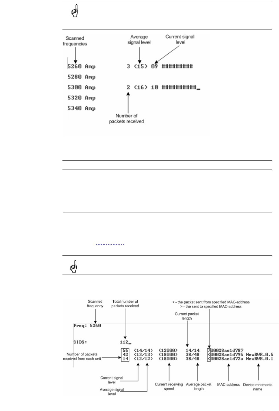
InfiNet Wireless R5000 Technical User Manual
Copyright © 2004-2006 by InfiNet Wireless Limited. 37
what frequencies can be used for the link so that the link did not interfere with
other sources of signals.
The scan is performed only for the packets corresponding with the
standard of the radio module (802.11a for 5GHz devices and 802.11b
for 2.4 GHz devices. Other sources of signals on the scanned
frequencies stay unseen.
The picture above shows the output of review mode.
To run the review mode please type the following command:
muffer <IF-NAME> review
Once the link is established you can use this mode to review the activity on the
configured for frequency for the link. If no activity is observed that means that
the signal from the remote side is being broken by the interference sources or by
the obstacles on the signal propagation path.
MAC2 mode
This regime performs MAC-addresses analysis to estimate the number of clients
with different MAC addresses and the efficiency of their utilization of the air link.
The analysis is carried out for all MAC addresses at the frequency previously
specified by rfconfig command. The mac2 regime checks both data packets
and the link-level ACK messages sent by protocol supported devices.
Normal operation of the radio is not possible in this mode.
The picture below shows the output mac2 regime.
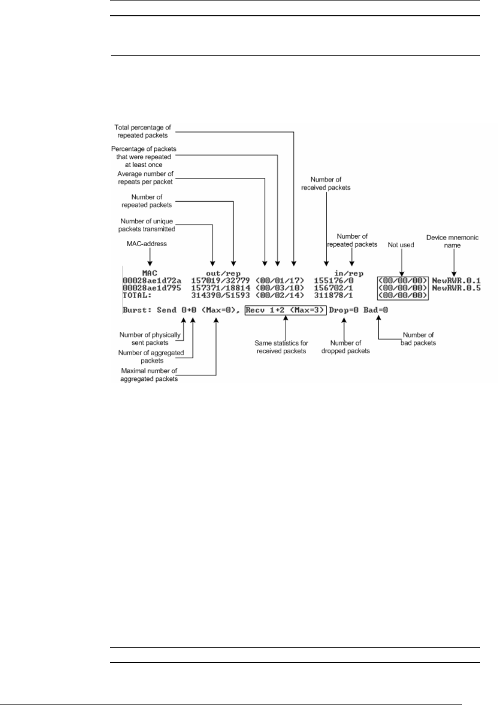
InfiNet Wireless R5000 Technical User Manual
Copyright © 2004-2006 by InfiNet Wireless Limited. 38
Like in review mode this regime provides with the information about a current
activity but on the configured frequency.
To run the review mode please type the following command:
muffer <IF-NAME> mac2
Statistics
The statistics gathering is used for estimating link load intensity and per client.
The amount of packets sent and received, and the number of retransmissions is
shown for each MAC address participating in the data exchange.
The statistics output is presented in the picture below.
The following decisions can be made by analyzing the outputted parameters:
• If the number of repeated packets is comparable with total number of
packets that means that you might have an interference source on the
selected frequency. For normally operating link the percentage of
repeated packets should not exceed 10%. It is extremely important to
obtain a permanent zero value for the average number of repeats per
packet. If the value is not zero that means that the link is NOT working
properly and requires further improvement
• If total percentage of repeated packets and the percentage of packets
that were repeated at least once are close to each other that might
mean that you have got a permanent source of interference. Otherwise,
it means that a strong interference source appears from time to time
breaking your signal
• Concerning the fact that statistics module outputs the information for
each MAC-address separately, you can reveal the problem for some
specific unit on the wireless network
The “muffer stat” command shows the statistics only from registered devices.
To view statistics type the following command:
muffer stat
To reset all counters please type
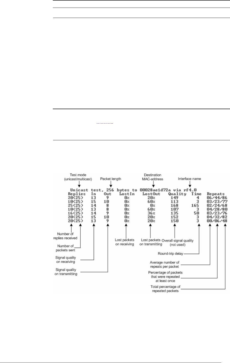
InfiNet Wireless R5000 Technical User Manual
Copyright © 2004-2006 by InfiNet Wireless Limited. 39
muffer stat clear
Other modes of muffer
The muffer also has the following modes:
• mac mode. Compared to the mac2 mode this mode does not take link-
level ACK messages sent by protocol support devices into account
• mynet mode performs the radio testing without disturbing radio
module's normal operation, but taking into account only packets from
within the given network
• sid mode. The sid regime allows estimating the number of currently
operating subscriber groups having different identifiers (SID), and the
efficiency of air links utilization. The analysis is carried out for all network
identifiers at the frequency previously specified for the radio module by
rfconfig command.
RMA Test
RMA test modes are used for estimating the quality of the established link.
Compared to the muffer mode these modes are not passive and involve
transmitting packets to the radio media.
Manual testing
Manual test of a link to a subscriber unit or base station with specified MAC-
address. Any device can be tested in this mode, and testing results can be seen
on the console and on the front panel LED indicators.
The output in this mode in presented in the picture below.
This mode can be very useful when run of one of the ends of a wireless link
whereas the antenna alignment procedure and/or configuration manipulations
are carried out on the other end of the link. Thus, having mobile phone handy or
other communicating devices you can set up the link for the best performance.
Varying the packet length and the test mode (unicast/multicast) you can obtain
the required link quality for the specific subscriber unit. In unicast mode (default
mode) one should obtain zero values for LostIn and LostOut parameters even
when the packet length is long (e.g. 1400 bytes). For multicast mode the
threshold value below which the link can be defined as satisfactory is
approximately 20% of lost packets.

InfiNet Wireless R5000 Technical User Manual
Copyright © 2004-2006 by InfiNet Wireless Limited. 40
Example of rma test mode usage for manual mode:
rma rf4.0 test ab1 1400 mcast
Here:
• Test key word means that the test is performed in the manual mode
• Ab1 – system assigned name for the subscriber (do not mix with a
mnemonic subscriber name, see rma ab section). You can use
subscriber MAC-address instead
• 1400 – testing packet length
• mcast – multicast mode. If not specified the unicast packets are sent
Automatic RMA test modes
Two automatic test modes are available: using MAC-address (no registration)
and with registration on the BS. In the second case the subscriber searches for
the BS specified in its configuration and afterwards the testing starts using MAC-
address of the found BS.
Example (deferred test using MAC-address):
rma rf4.0 auto 00:00:0e:12:13:ac 2048 mcast
config save
Example (Base Station search test):
rma rf4.0 autobs 2048 mcast
config save
To disable automatic test modes, please type:
rma rf4.0 -autotest
config save
Load Meter
Load meter is a powerful tool that allows estimating the load of a system
interface specified by interface parameter. By default, the information is
displayed on one line and updated every second; the load is measured in
kilobytes.
Below picture shows the load meter output for the radio interface outputted in
line-by-line mode with one second interval.
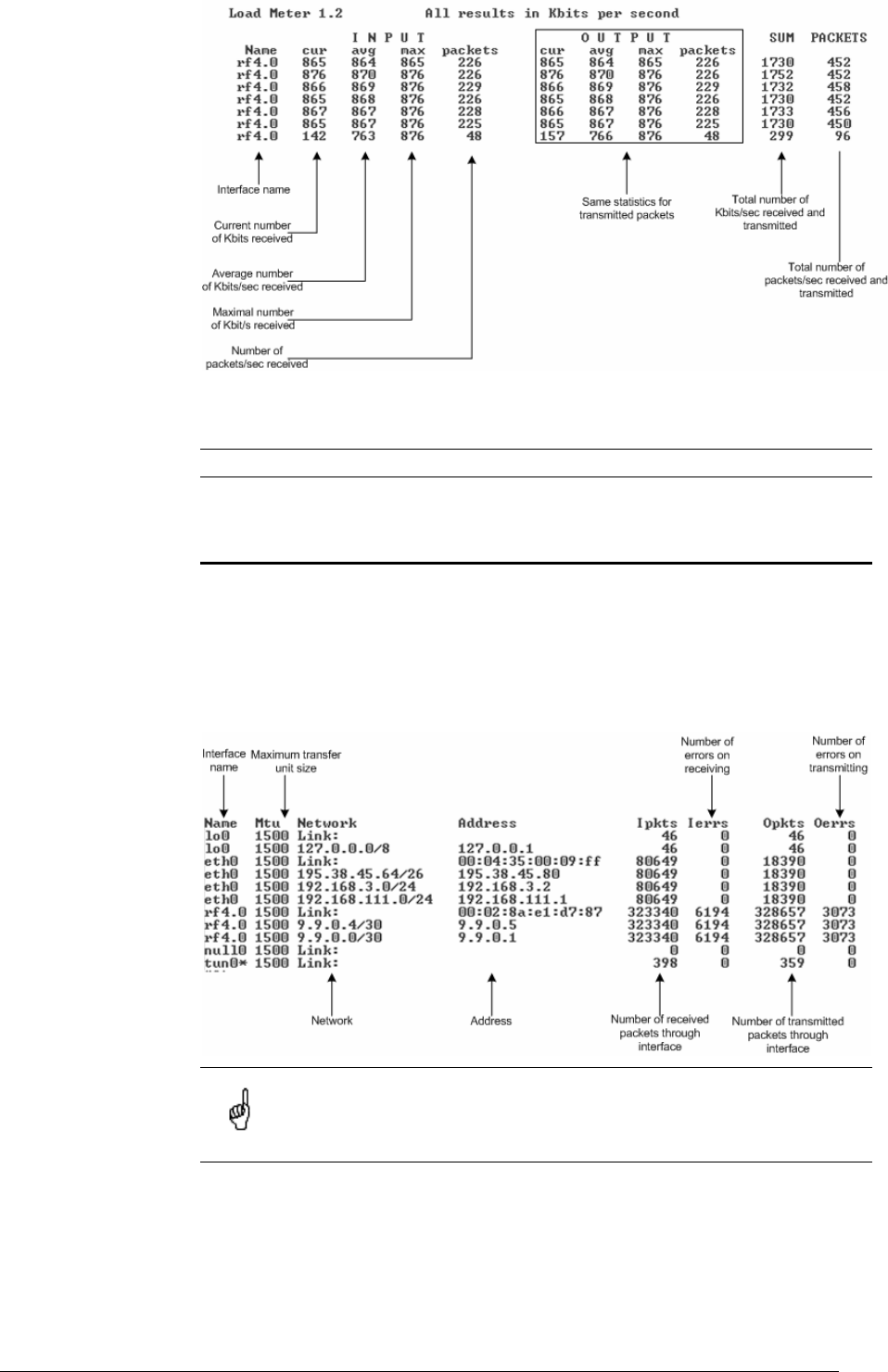
InfiNet Wireless R5000 Technical User Manual
Copyright © 2004-2006 by InfiNet Wireless Limited. 41
To run load meter like it is shown above, please type:
loadm –l <IF-NAME>
Acquiring interfaces statistics
Interface statistics can be acquired using netstat module which includes two
modes:
• Routing tables output (using “-r” parameter with the command)
• Interfaces statistics output (using “-I” parameter with the command)
Below picture shows the example of interfaces statistics output.
If the interface has several aliases the statistics is still measured for
physical interface in a whole. For example, see rf4.0 or eth0 interfaces
above. The numbers shown in 4 right columns correspond in physical
interface.

InfiNet Wireless R5000 Technical User Manual
Copyright © 2004-2006 by InfiNet Wireless Limited. 42
VI. Services, features and tools
This chapter describes router’s built-in services, features and tools which were
not described in previous parts of the document. Descriptions provided in this
chapter are shortened. Full description is available in the OS WANFlex User
Guide.
1. Network services
MAC filter
The MAC filter (macf command) performs static mapping of IP-addresses to
MAC addresses in an Ethernet network. It may be useful for service providers
when they connect to their network a group of clients (such as individual users in
an apartment block) via one common access unit. In this case, clients may be
tempted to change their IP address to that of a neighbor, thus deceiving
provider's accounting system. Although it is almost impossible to definitely
resolve this issue, you can make however your life easier by directly mapping the
client's assigned IP-address to his/her MAC-address, because surreptitiously
modifying a MAC address is much more difficult for an average user.
NAT
NAT - network address translation according to rfc1631
NAT (nat command) allows solving to the certain extent the problem IPv4
address space exhausting. It means that several computers in the given LAN
may connect to Internet via the same public IP address. NAT-module receives
outgoing IP-packets, modifies sender's IP address to the public IP address and
forwards it to Internet. Sender's IP address is modified in such a way that it is
possible to identify the sender when IP packet received on the LAN incoming
interface and to forward the IP packet to the initial sender. NAT-module is similar
to natd and libalias from FreeBSD. Original manuals can help understand the
subject better.
Full support of H.323 protocol.
IP firewall
IP Firewall (ipfw command) is a mechanism of filtering packets crossing an IP
network node, according to different criteria. System administrator may define a
set of incoming filters (addincoming) and a set of outgoing filters
(addoutgoing). The incoming filters determine which packets may be accepted
by the node. The outgoing filters determine which packets may be forwarded by
the node as a result of routing.
Each filter describes a class of packets and defines how these packets should be
processed (reject and log, accept, accept and log).
Packets can be filtered based on the following properties:
• Protocol (IP, TCP, UDP, ICMP);
• Source address and/or destination address (and port numbers for TCP
and UDP);
• The network interface it arrived on;
• Whether the packet is a TCP/IP connection request (a packet attempting
to initiate a TCP/IP session) or not;
• Whether the packet is a head, tail or intermediate IP fragment;
• Whether the packet has certain IP options defined or not;

InfiNet Wireless R5000 Technical User Manual
Copyright © 2004-2006 by InfiNet Wireless Limited. 43
• The MAC address of the destination station or of the source station.
QoS
QoS manager (qm command) is a convenient and flexible mechanism to
manipulate data streams going through the router. The user can create up to 64
logical channels characterized by different properties (such as priority levels and
data transfer rates), and then assign data streams to these logical channels
according to special rules of assignment. Packets going through different
channels are thus modifying their own properties as well as properties of their
respective data flows.
QoS application:
• Traffic shaping
• Traffic prioritization
• Traffic redirection
Tunneling
There are several approaches for tunnels building. One of them is IP into IP
Encapsulation (described in RFC 2003). It is implemented in OS WANFleX (tun
command). This technology is used, for example, in Cisco Systems routers, and
is a subset of the IPSEC protocol supported by several operating systems.
Within this approach, tunnels are implemented as point-to-point (P2P) links
between two endpoint routers. The whole data stream through such a link is
encapsulated into IP packets at one end of a link and is delivered to its opposite
end through the existing transport network.
Routing core
InfiNet Wireless Router supports the standard TCP/IP (IPv4) protocols stack.
2. Utilities and services
Telnet
Telnet system protocol support.
Telnet command sets up a connection with a remote host specified by the IP-
address in the terminal emulation mode. The telnet command uses transparent
symbols stream without any intermediate interpretation; therefore, the terminal
type is defined by the terminal from which the command has been executed
Ping
Ping command sends test packets (ICMP_ECHO_REQUEST) to the given IP-
address. Enables to estimate attainability of a host and the destination response
time.
Access control lists
While network planning you may often need to group similar parameters in lists
which can be used for different filters. Access control lists (acl command) can
effectively solve this problem.
The ACL command creates an access list the specified name and type.

InfiNet Wireless R5000 Technical User Manual
Copyright © 2004-2006 by InfiNet Wireless Limited. 44
3. Routing protocols
Static
The router has a feature of creating static routing tables
The route command provides with manual management of system routing
tables. In the normal mode, when a routing daemon is active, this command is
not needed. However, in some cases it allows to achieve more precise, non-
standard configuration.
All routes that are described using route add command are “pseudostatic”. It
means that this information will be immediately placed into the configuration and
will be active until it is deleted using route delete command. However, actually
described routes will be put into the system tables only when there is an
interface with an address and a mask within the boundaries of the gateway
address set. When this address is absent routes set will be automatically deleted
from system tables but still will be present in the configuration
RIP
The routing module supports two versions of the Routing Information Protocol:
RIP-1 and RIP-2. The rip command is used to set up the module for using these
routing protocols.
4. Management features
HTTP
The HTTP protocol support module (httpd command) makes it possible to
configure the router using any Web browser. A mini-server built into the router
provides for executing any WANFleX command, and also some predefined
scripts.
RSH
RSH (remote shell) protocol support module.
The built-in RSH server makes it possible remote command execution using the
rsh command. Identification is based on using privileged TCP ports and a list of
authorized hosts.
SNMP
Simple Network Management Protocol version 3 support.
SNMP support (snmp command) is an important feature supported by the router
as it provides the network administrator with a control over the whole system
and any of its components.
Console
The router has a feature of its configuration management via console. By
specifying the correct parameters of the RS-232 interface and connecting the
device via console cable one can get an access to the WanFlex OS command
prompt in order to configure the device.

InfiNet Wireless R5000 Technical User Manual
Copyright © 2004-2006 by InfiNet Wireless Limited. 45
VII.GUI “InfiNet Wireless Router Manager”
1. Overall functionality overview
“InfiNet Wireless Router Manager” (“IWR Manager” for short”) is used for the
following purposes:
• View and change system parameters of the router
• View and change interfaces parameters of the router
• Obtain ARP table and routing table
• View interfaces statistics and interfaces current load statistics
• Setting up the router as a BS or/and CPE
• View CPEs parameters if the router acts as a BS
• View BS registration parameters if the router acts as a CPE
• Separate Telnet session for console management
The application is designed for OS Windows.
2. Application requirements
In order to run and properly use the application, the following requirements
must be met:
• InfiNet Wireless R5000, single-radio
• OS WANFleX version 3.36 or higher
• SNMP agent is running (snmp enable command)
• Before starting the application, not more than 3 session of Telnet should
be opened for this particular router
• Automatic screen messaging must be turned off (sys log off command)
3. User guide
In the authorization window please enter login, password, SNMP community
name, IP-address of the router. In case if one of the listed parameters is
incorrect, the user gets one of the following error messages:
• SNMP test failed. The message states that the application is unable to
work with the router using SNMP protocol. Amongst the reasons for this
error messages one can state the following:
o SNMP Community name is incorrect
o SNMP agent is not run on the router
• Client socket error. The error message means that the application
cannot establish the connection with the router using Telnet protocol.
The reasons may be the following:
o Login is incorrect
o Password is incorrect
o IP-address is incorrect or the router is not attainable via IP
If authorization went well, the user will be able to see “IWR Manager” window
after all parameters had been downloaded from the router.
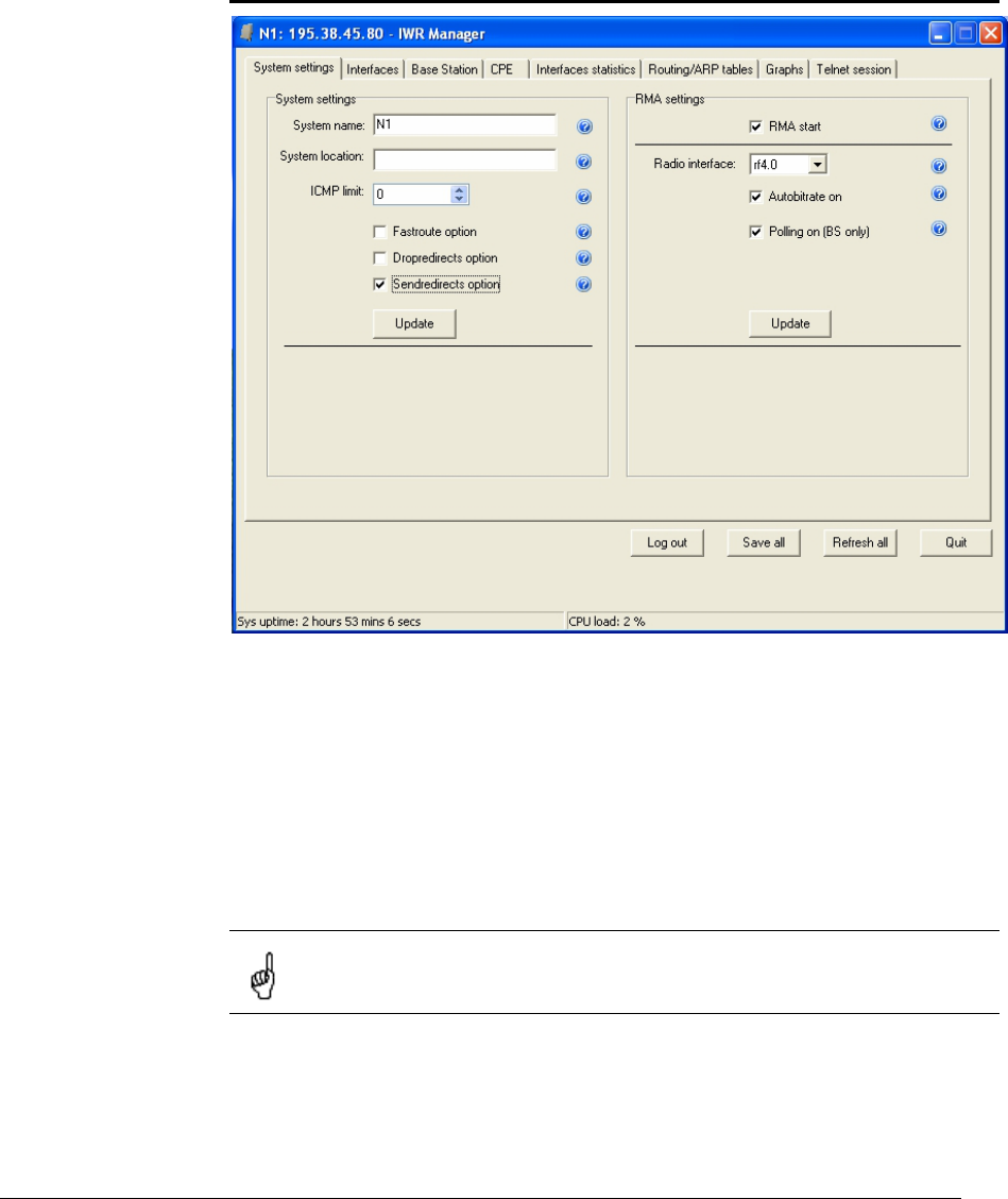
InfiNet Wireless R5000 Technical User Manual
Copyright © 2004-2006 by InfiNet Wireless Limited. 46
In system panel at the bottom of the window the following parameters are
permanently updated:
• Sys uptime. A time since last device’s reboot.
• CPU load. Current CPU load.
Also, a set of buttons is also available at the bottom of the window:
• Save all. Saves all changes. Equivalent to “config save” command.
• Refresh all. Updates all information is all tabsheets.
• Quit. Closes the application.
System settings
The following system parameters can be changed/viewed in this sheet:
• System name
• Optional parameter setting a geographical location of the router
RMA protocol manipulations:
• Starting/stopping the protocol
• Turning on/off the autobitrate mechanism
• Turning on/off the polling mechaism
Parameters are usually united in groups with one common “Update”
button at the bottom of the group (e.g. “RMA settings”). Unless the
button is not pressed all changes in the group does not have power.
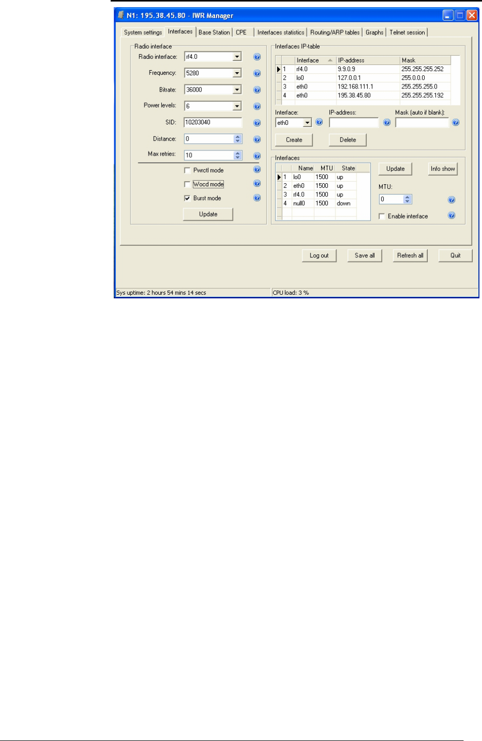
InfiNet Wireless R5000 Technical User Manual
Copyright © 2004-2006 by InfiNet Wireless Limited. 47
Interfaces
Among all interfaces parameters that can be adjusted in this tabsheet, the most
important are radiointerface parameters:
• Working frequency. Usually this parameter is relevant only for BS. For
the CPE the frequency (or a list of frequencies) is set in RMA protocol
configuration and determines the list of frequencies where the BS should
be searched.
• The bit transfer rate (in Kbit/s) of the radio link.
• Power of a transmitter (in milliwatts). The values of acceptable trasmit
power levels can vary depending on the type of radio module installed.
The full list of acceptable trasmit power levels is available by using "rf if-
name capabilitites" command. If the value entered is invalid the system
will automatically set a minimal adjacent value.
• System identifier of the router, a hexadecimal number in the range of 1H
to FFFFFFH. All routers that are supposed to see each other on the same
radio link must have the same identifier. To be compatible with ARLAN
655 network adapters, the identifier must be an even number. For 11
Mbit/s radio modules (PC4800, Lucent ORINOCO etc) the identifier must
be entered as a string of 6 hexadecimal digits (using digits 0 to 9 and
CAPITAL letters A to F), with leading zero's when necessary, e.g.
00A2CD.
• Distance. this parameter is used as an alternative method of link range
configuring in order to set the exact distance value between two devices
(in kilometers). This parameter changes time values for some delays and
time-outs of 802.11a/b/g protocol thus making possible to work on
longer distances with smooth adjustment.
There are several ways to manage this parameter:
o if you set an exact value, this value is used no matter what the
connection method is used

InfiNet Wireless R5000 Technical User Manual
Copyright © 2004-2006 by InfiNet Wireless Limited. 48
o If the CPE has auto value instead of a number (by default), the
CPE will configure its parameters using Base Station commands.
It is enough to set a numeric value on a Base Station (the
distance to the remotest CPE); all other CPEs will automatically
adjust their work. While configuration showing, there might be
the current distance value after auto parameter: auto (XX)
o when knowing exact device's geographical coordinates (e.g.
using GPS) you can specify their values in sys gpsxy command
and distance parameter set as auto on all devices including the
Base Station. In this case devices will automatically adjust their
settings selecting an optimal value for the distance parameter.
Base Station will calculate a distance to the remotest subscriber,
and subscriber will calculate a distance to the base station. If the
CPE has a link coordinates information it will use this
information, otherwise it will use the distance parameter value
got from the base station.
Using several checkboxes you can manage different regimes for the radio:
• wocd mode. Disables carrier sense on the radio interface when sending
data packets. May only be used on a base station working in WMA
(Wireless Marker Access) mode. Reduces the number of retransmitted
packets, thus increasing effective throughput of a multipoint radio link. "-
vocd" re-enables the standard mechanism of permanent carrier sense.
Initial setting is "-wocd" (carrier sense enabled).
• burst mode consists in grouping several short packets with the same
destination address on a radio link into larger packets, thus cardinally
decreasing the response time for applications generating streams of
short packets..
• pwrctl enables automatic management of transmitter's emitting power.
Along with radiointerface parameters, the user can view/change other interfaces
parameters::
• eth0 – Ethernet interfaces
• lo0 – Loopback interface
• null0 – auxiliary interface
The application has the following functionality to manage the interfaces:
• Add/delete/change primary and secondary (alias) IP-address on each
interface
• Change the state of the interfaces (up/down).
• Change MTU (Maximum Transfer Unit) parameter for each of the
interfaces
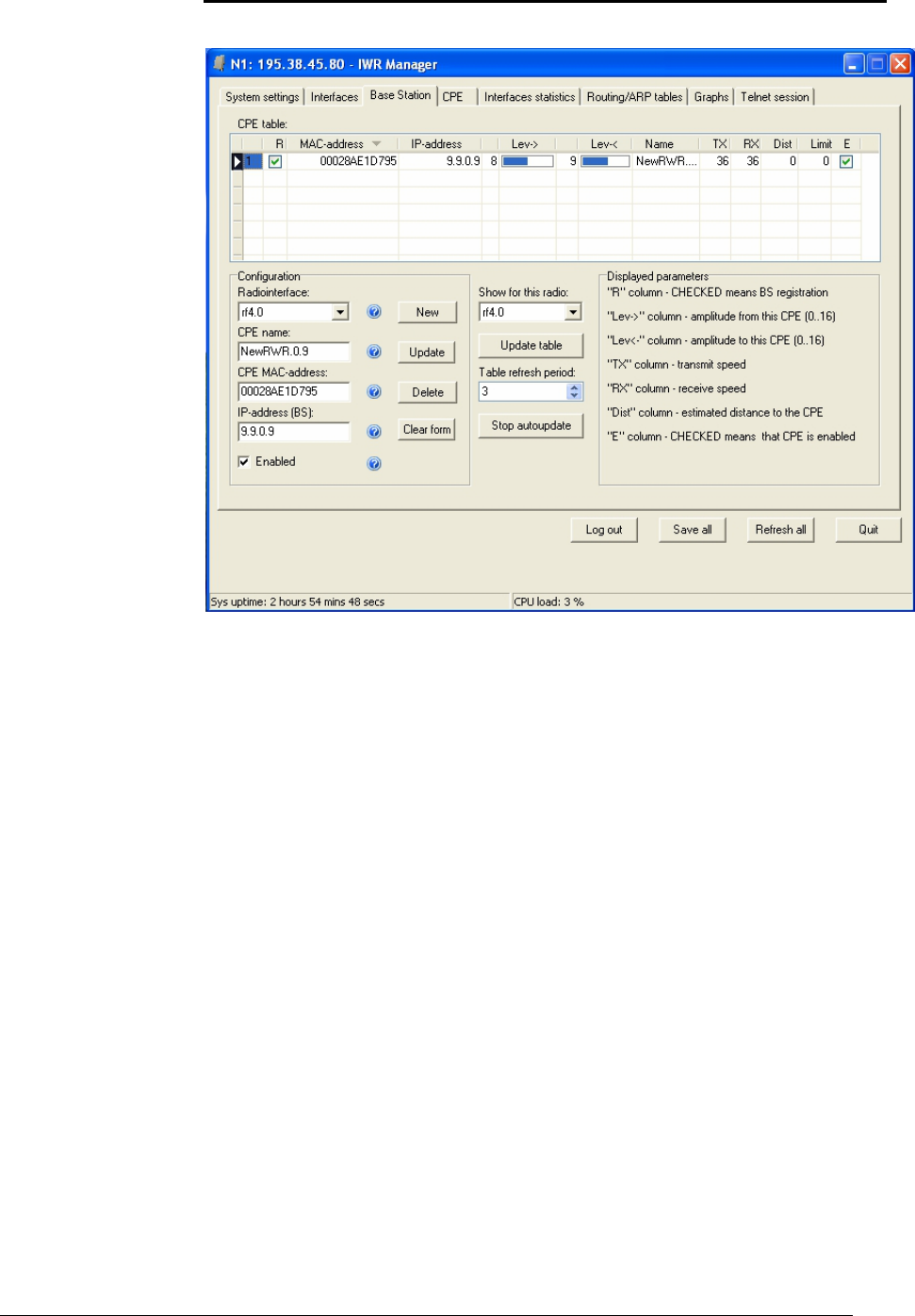
InfiNet Wireless R5000 Technical User Manual
Copyright © 2004-2006 by InfiNet Wireless Limited. 49
Base Station
In this Tabsheet the user can edit the following parameters:
• Create/delete/edit records for the CPEs that can register on this Base
Station. Each record corresponds with “rma ab” string in RMA protocol
configuration
• Manual CPEs switching on/off
The application is capable of periodic update of the CPE current information
which includes:
• BS registration status
• Signal levels from BS to CPE and from CPE to BS. Signal levels are
measured from 1 to 16
• Upstream and downstream speeds
• Distance to the Base Station
• Mnemonic name of the CPE
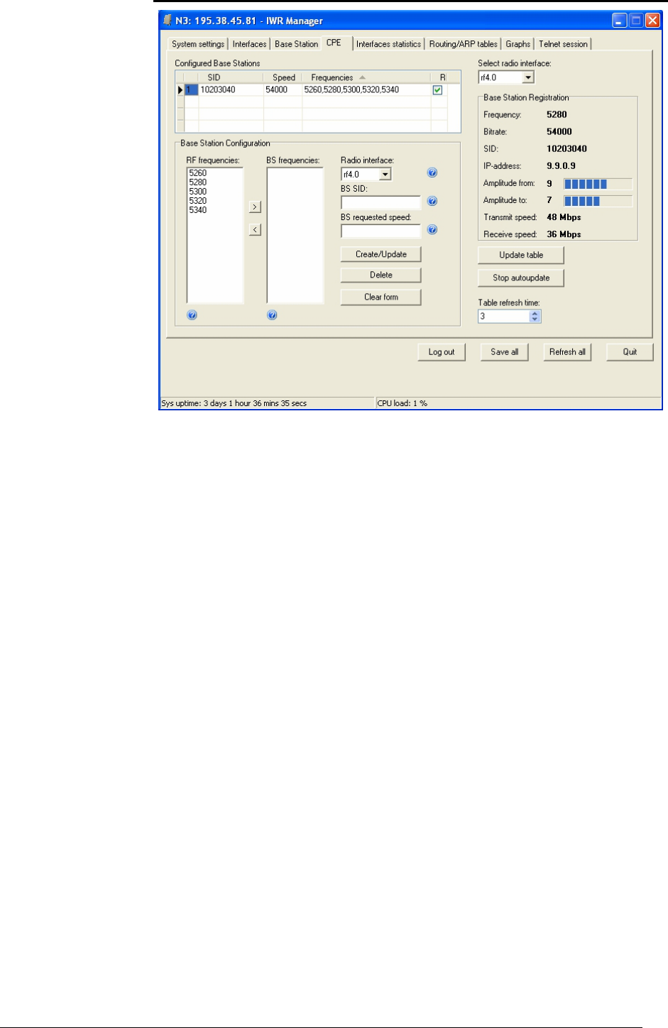
InfiNet Wireless R5000 Technical User Manual
Copyright © 2004-2006 by InfiNet Wireless Limited. 50
CPE – Customer Premises Equipment)
For each CPE there can be several configured BS. Surely, CPE at the moment can
be registered only at one BS. Each BS is represented by three parameters: SID
of the searched BS, requested transmitting speed and list of frequencies where
the BS should be searched at. Each time RMA is run or CPE looses registration at
the BS, it starts searching for a new BS scanning through the list of configured
BS.
If CPE is registered at the BS, the application will show all the registration
parameters and, if required, update them periodically:
• BS working frequency
• Requested speed from the BS
• System identifier (SID)
• IP-address for the radiointerface from the side of the BS. For CPE, the
address for the radiointerface will be assigned automatically.
• Signal levels from BS and to BS
• Current upstream and downstream speeds
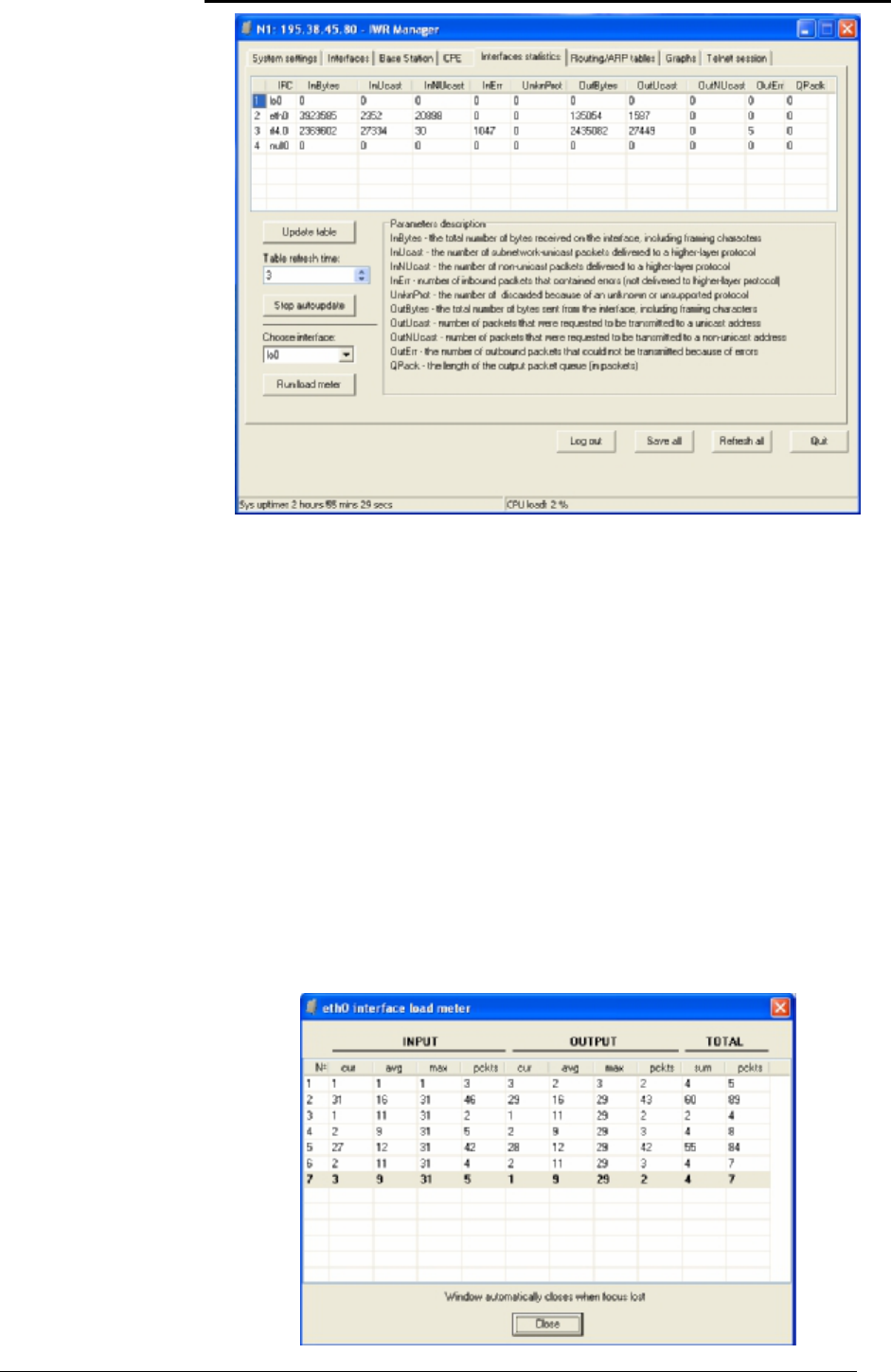
InfiNet Wireless R5000 Technical User Manual
Copyright © 2004-2006 by InfiNet Wireless Limited. 51
Interfaces statistics
Prompts and hint available in this tabsheet provide the user with all necessary
information on all displayed parameters.
Also, the page has a feature of running a load meter which provides with a
detailed information on interfaces load dynamics. The parameters which are
shown by load meter are the following:
• INPUT/OUTPUT: cur – number of received/sent kilobits/sec through
the interface
• INPUT/OUTPUT: avg – the average number of received/sent
kilobits/sec through the interface normalized by the time of observation
• INPUT/OUTPUT: max – the maximal number of received/send
kilobits/sec through the interface normalized by the time of observation
• INPUT/OUTPUT: pckts – total number of incoming/outgoing pps
through the interface
• TOTAL: sum – total number of kbps that went through the interface
• TOTAL: pckts – total number of pps went through the interface
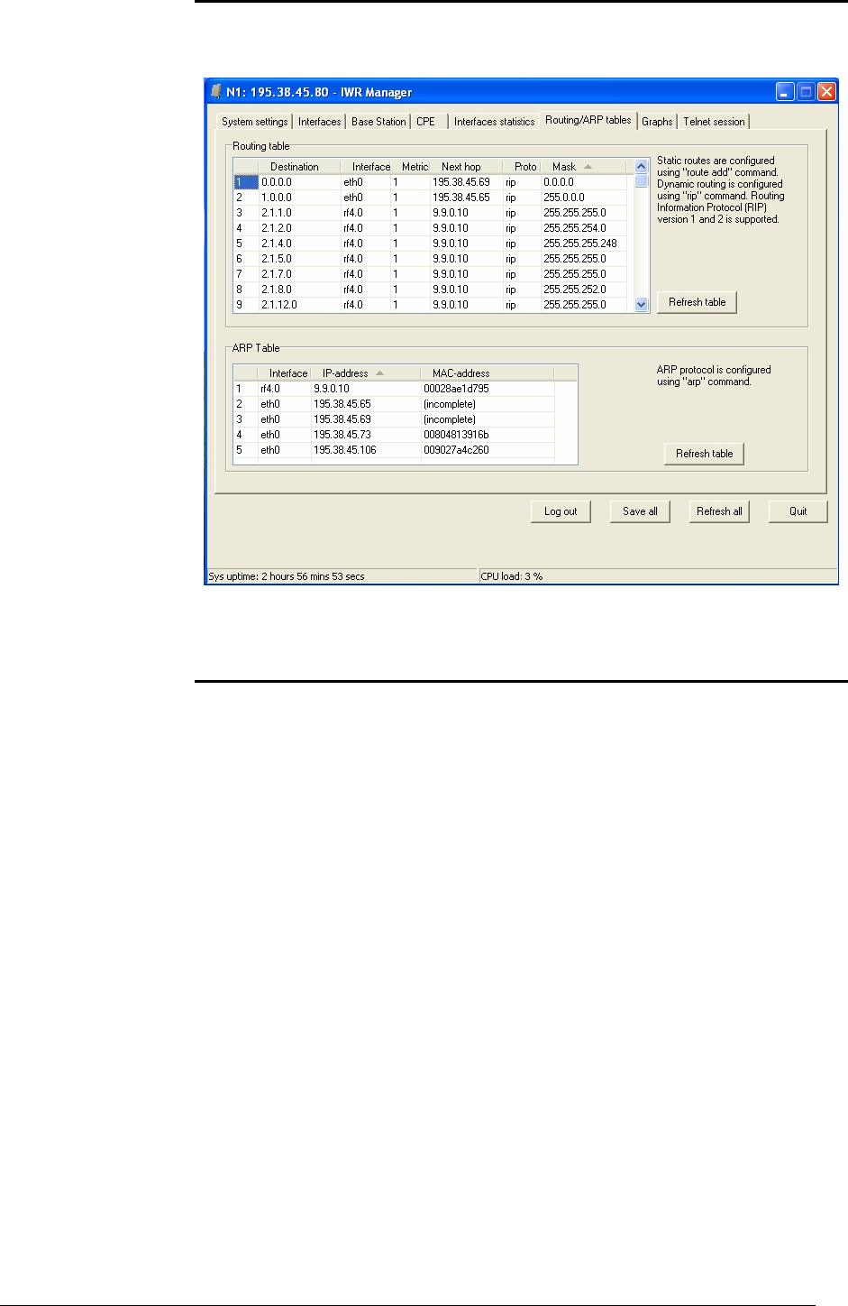
InfiNet Wireless R5000 Technical User Manual
Copyright © 2004-2006 by InfiNet Wireless Limited. 52
Routing/ARP tables
This Tabsheet lets the user to view routing table and ARP-table..
Graphs
This Tabsheet contain three subsheets:
• CPU Load. Builds a graph, showing CPU load changing in time
• CPE signal levels. Shows how levels from different CPEs change in time
• Interfaces Graphs. Displays current load on all interfaces.
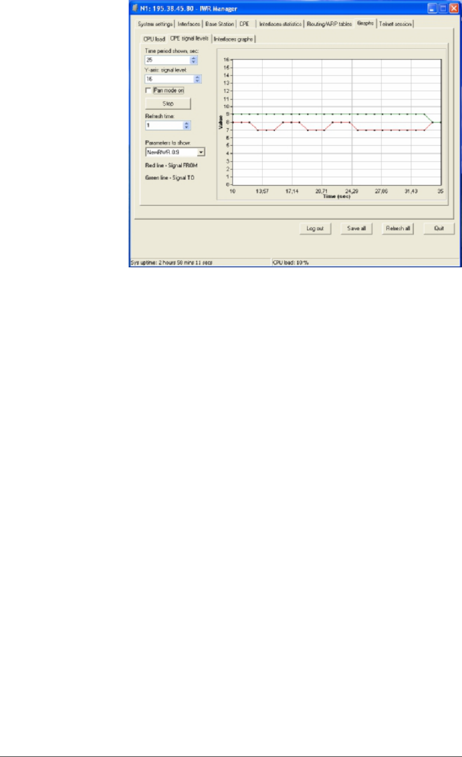
InfiNet Wireless R5000 Technical User Manual
Copyright © 2004-2006 by InfiNet Wireless Limited. 53

InfiNet Wireless R5000 Technical User Manual
Copyright © 2004-2006 by InfiNet Wireless Limited. 54
VIII.Recommendations
1. Using InfiNet Devices for High Speeds (48, 54 Mbps)
Using InfiNet devices on greater speeds 48 and 54 Mbps can specific limitations
and requirements because of low noise immunity of high-order modulation
techniques (64 QAM).
One should take all possible precautions to prevent exceeding of parasite signals
over receiver sensitivity threshold. The problem is aggravated by the presence of
this parasite signal in entire spectrum. This practically is not impossible to
achieve when there are other active devices in neighborhood and therefore such
high speed devices can be used only in autonomous links.
2. Design of Multi-sectored Base Stations
Based on the above, we can resume that it is possible to build only single-
sectored base station for high speeds and building multi-sectored base stations is
possible only for speeds less than 36 Mbps. More than that, there is trade-off
between coverage and speed. The more powerful base station we have
(amplifiers, greater range), the less speeds can be defined for this base station.
So we have ultimate choice: either optimizing base station for more speed/less
range (without amplifiers) or optimize base station for more range/less speed
(with amplifiers).
Compromise is achieved by using amplifiers and directional antennas at remote
subscribers, but this approach essentially is more costly.
Remote subscribers can be configured for significantly lower than average
speeds providing more stable operating modes but those subscribers can
decrease overall cell performance; so try to avoid mix solutions when the BS-CPE
has a big difference for different subscribers.
3. Asymmetrical System Design
Following conclusions regarding using base station can be made:
• Downstream speed (base to CPE) is usually higher than upstream;
• Beam width of base station sectored antenna is 10 times wider than
beam width of subscriber antenna;
• Trying to deploy base stations on area heights leads to raising overall
noise level and reducing noise immunity;
• Subscriber SNR measured at a base station is significantly worse than
that of subscriber side.
• Increasing transmit speed does not influence the overall working
conditions and network performance;
• Increasing receive speed does worsen noise immunity and network
performance.
Every step in speed increasing requires 3 dB step improvements SNR.
Asymmetry in 8 times corresponds to 9 dB. It means that without link quality
losses we can have 2 times speed difference between upstream and
downstream. In order to maintain energetic parameters, we have to increase
base station output power by 9 dB by means of built-in amplifier. Other option is
to install external amplifier at subscriber side, because it has more gain for
receiving than for transmitting.
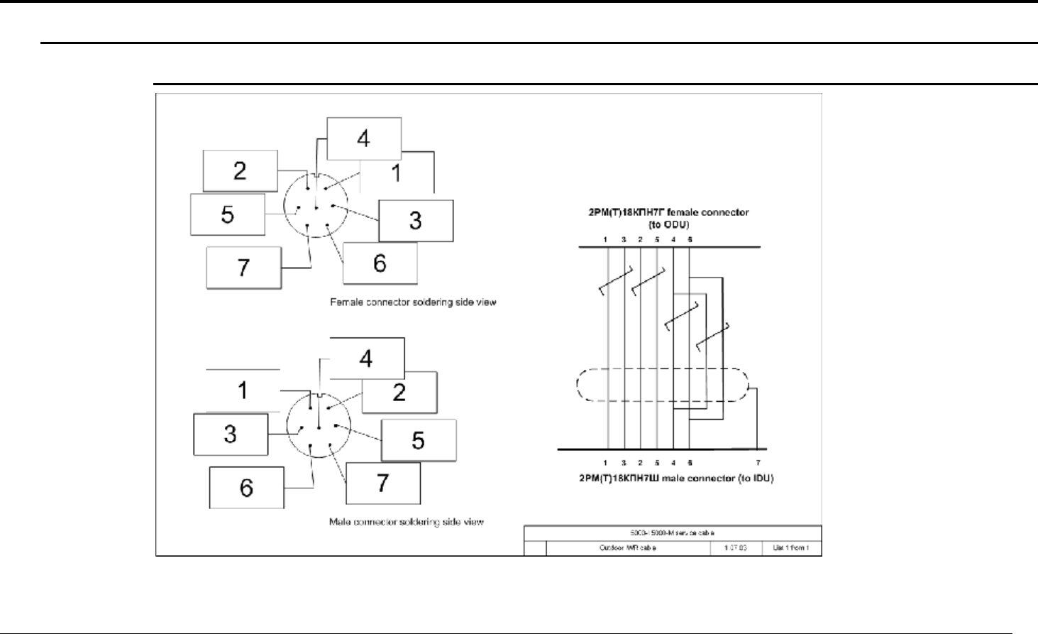
InfiNet Wireless R5000 Technical User Manual
Copyright © 2004-2006 by InfiNet Wireless Limited. 55
IX. Supplementary information
1. Connectors soldering schemes
Service cable connector soldering scheme
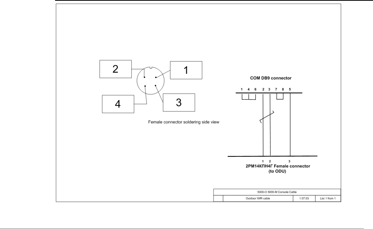
InfiNet Wireless R5000 Technical User Manual
Copyright © 2004-2006 by InfiNet Wireless Limited. 56
Console cable connector for 5000-M and 5000-O soldering scheme