Infiniti 2012 G37 Maintenance Manual Config(MA)
2015-10-23
: Infiniti Infiniti-2012-Infiniti-G37-Maintenance-Manual-817295 infiniti-2012-infiniti-g37-maintenance-manual-817295 infiniti pdf
Open the PDF directly: View PDF ![]() .
.
Page Count: 58
- QUICK REFERENCE INDEX
- Table of Contents
- PREPARATION
- PERIODIC MAINTENANCE
- GENERAL MAINTENANCE
- PERIODIC MAINTENANCE
- RECOMMENDED FLUIDS AND LUBRICANTS
- ENGINE MAINTENANCE (VQ37VHR)
- ENGINE MAINTENANCE (VQ25HR)
- CHASSIS MAINTENANCE
- EXHAUST SYSTEM
- GEAR OIL
- CLUTCH FLUID
- A/T FLUID
- TRANSFER FLUID
- FRONT PROPELLER SHAFT: 2S56A
- REAR PROPELLER SHAFT: 3S80A
- REAR PROPELLER SHAFT: 3S80A-R
- REAR PROPELLER SHAFT: 3F80A-1VL107
- FRONT DIFFERENTIAL GEAR OIL: F160A
- REAR DIFFERENTIAL GEAR OIL: R200
- REAR DIFFERENTIAL GEAR OIL: R200V
- WHEELS (BONDING WEIGHT TYPE)
- BRAKE FLUID LEVEL AND LEAKS
- BRAKE LINES AND CABLES
- BRAKE FLUID
- DISC BRAKE
- STEERING GEAR AND LINKAGE
- POWER STEERING FLUID AND LINES
- AXLE AND SUSPENSION PARTS
- DRIVE SHAFT
- BODY MAINTENANCE
- SERVICE DATA AND SPECIFICATIONS (SDS)

MA-1
MAINTENANCE
C
D
E
F
G
H
I
J
K
L
M
B
MA
SECTION MA
N
O
A
CONTENTS
MAINTENANCE
PREPARATION ............................................ 4
PREPARATION ................................................... 4
Special Service Tool .................................................4
Commercial Service Tool ..........................................4
PERIODIC MAINTENANCE .......................... 5
GENERAL MAINTENANCE ................................ 5
FOR NORTH AMERICA ..............................................5
FOR NORTH AMERICA : Explanation of General
Maintenance ..............................................................5
FOR MEXICO ..............................................................6
FOR MEXICO : General Maintenance ......................7
PERIODIC MAINTENANCE ................................ 9
FOR NORTH AMERICA ..............................................9
FOR NORTH AMERICA : Introduction of Periodic
Maintenance ..............................................................9
FOR NORTH AMERICA : Schedule 1 ......................9
FOR NORTH AMERICA : Schedule 2 ....................12
FOR MEXICO ............................................................14
FOR MEXICO : Periodic Maintenance ....................14
RECOMMENDED FLUIDS AND LUBRI-
CANTS ................................................................17
FOR NORTH AMERICA ............................................17
FOR NORTH AMERICA : Fluids and Lubricants ....17
FOR NORTH AMERICA : Engine Oil Recommen-
dation ......................................................................18
FOR NORTH AMERICA : Anti-Freeze Coolant
Mixture Ratio ...........................................................18
FOR MEXICO ............................................................18
FOR MEXICO : Fluids and Lubricants ....................19
FOR MEXICO : SAE Viscosity Number ..................19
FOR MEXICO : Engine Coolant Mixture Ratio ........21
ENGINE MAINTENANCE (VQ37VHR) ..............22
DRIVE BELT ..............................................................22
DRIVE BELT : Exploded View .................................22
DRIVE BELT : Checking ..........................................22
DRIVE BELT : Tension Adjustment ........................22
ENGINE COOLANT ...................................................22
ENGINE COOLANT : Draining ................................22
ENGINE COOLANT : Refilling .................................23
ENGINE COOLANT : Flushing ................................25
FUEL LINES ...............................................................26
FUEL LINES : Inspection .........................................26
AIR CLEANER FILTER .............................................26
AIR CLEANER FILTER : Removal and Installation
....26
ENGINE OIL ...............................................................26
ENGINE OIL : Draining ............................................26
ENGINE OIL : Refilling ............................................27
OIL FILTER ................................................................27
OIL FILTER : Removal and Installation ...................27
OIL FILTER : Inspection ..........................................29
SPARK PLUG ............................................................29
SPARK PLUG : Removal and Installation ...............29
SPARK PLUG : Inspection ......................................29
EVAP VAPOR LINES ................................................30
EVAP VAPOR LINES : Inspection ...........................30
ENGINE MAINTENANCE (VQ25HR) ................31
DRIVE BELT ..............................................................31
DRIVE BELT : Inspection ........................................31
DRIVE BELT : Adjustment .......................................31
ENGINE COOLANT ...................................................32
ENGINE COOLANT : Draining ................................32
ENGINE COOLANT : Refilling .................................33
ENGINE COOLANT : Flushing ................................35
FUEL LINES ...............................................................36
Revision: 2013 February 2012 G Sedan

MA-2
FUEL LINES : Inspection ........................................ 36
AIR CLEANER FILTER ............................................. 36
AIR CLEANER FILTER : Removal and Installation
... 36
ENGINE OIL .............................................................. 36
ENGINE OIL : Draining ........................................... 36
ENGINE OIL : Refilling ........................................... 37
OIL FILTER ............................................................... 37
OIL FILTER : Removal and Installation .................. 37
OIL FILTER : Inspection ......................................... 39
SPARK PLUG ........................................................... 39
SPARK PLUG : Removal and Installation .............. 39
SPARK PLUG : Inspection ..................................... 39
EVAP VAPOR LINES ................................................ 40
EVAP VAPOR LINES : Inspection .......................... 40
CHASSIS MAINTENANCE ................................ 41
EXHAUST SYSTEM .................................................. 41
EXHAUST SYSTEM : Inspection ........................... 41
GEAR OIL ................................................................. 41
GEAR OIL : Inspection ........................................... 41
GEAR OIL : Draining .............................................. 41
GEAR OIL : Refilling ............................................... 42
CLUTCH FLUID ........................................................ 42
CLUTCH FLUID : Inspection .................................. 42
A/T FLUID ................................................................. 42
A/T FLUID : Inspection ........................................... 42
TRANSFER FLUID .................................................... 42
TRANSFER FLUID : Inspection ............................. 42
TRANSFER FLUID : Draining ................................ 43
TRANSFER FLUID : Refilling ................................. 43
FRONT PROPELLER SHAFT: 2S56A ..................... 43
FRONT PROPELLER SHAFT: 2S56A : Inspec-
tion .......................................................................... 43
REAR PROPELLER SHAFT: 3S80A ....................... 44
REAR PROPELLER SHAFT: 3S80A : Inspection ... 44
REAR PROPELLER SHAFT: 3S80A-R .................... 45
REAR PROPELLER SHAFT: 3S80A-R : Inspec-
tion .......................................................................... 45
REAR PROPELLER SHAFT: 3F80A-1VL107 .......... 45
REAR PROPELLER SHAFT: 3F80A-1VL107 : In-
spection .................................................................. 45
FRONT DIFFERENTIAL GEAR OIL: F160A ............ 46
FRONT DIFFERENTIAL GEAR OIL: F160A : In-
spection .................................................................. 46
FRONT DIFFERENTIAL GEAR OIL: F160A :
Draining .................................................................. 46
FRONT DIFFERENTIAL GEAR OIL: F160A : Re-
filling ....................................................................... 47
REAR DIFFERENTIAL GEAR OIL: R200 ................. 47
REAR DIFFERENTIAL GEAR OIL: R200 : Inspec-
tion .......................................................................... 47
REAR DIFFERENTIAL GEAR OIL: R200 : Drain-
ing ........................................................................... 47
REAR DIFFERENTIAL GEAR OIL: R200 : Refill-
ing ........................................................................... 48
REAR DIFFERENTIAL GEAR OIL: R200V .............. 48
REAR DIFFERENTIAL GEAR OIL: R200V : In-
spection ................................................................... 48
REAR DIFFERENTIAL GEAR OIL: R200V :
Draining ................................................................... 48
REAR DIFFERENTIAL GEAR OIL: R200V : Refill-
ing ........................................................................... 49
WHEELS (BONDING WEIGHT TYPE) ..................... 49
WHEELS (BONDING WEIGHT TYPE) : Adjust-
ment ........................................................................ 49
BRAKE FLUID LEVEL AND LEAKS ........................ 51
BRAKE FLUID LEVEL AND LEAKS : Inspection .... 51
BRAKE LINES AND CABLES .................................. 52
BRAKE LINES AND CABLES : Inspection ............. 52
BRAKE FLUID ........................................................... 52
BRAKE FLUID : Changing ...................................... 52
DISC BRAKE ............................................................. 52
DISC BRAKE : Inspection ....................................... 52
DISC BRAKE : Front Disc Brake ............................ 53
DISC BRAKE : Rear Disc Brake ............................. 53
STEERING GEAR AND LINKAGE ........................... 53
STEERING GEAR AND LINKAGE : Inspection ...... 53
POWER STEERING FLUID AND LINES .................. 54
POWER STEERING FLUID AND LINES : Inspec-
tion .......................................................................... 54
AXLE AND SUSPENSION PARTS ........................... 54
AXLE AND SUSPENSION PARTS : Inspection ..... 54
DRIVE SHAFT ........................................................... 55
DRIVE SHAFT : Inspection ..................................... 55
BODY MAINTENANCE ..................................... 56
LOCKS, HINGES AND HOOD LATCH ..................... 56
LOCKS, HINGES AND HOOD LATCH : Lubricat-
ing ........................................................................... 56
SEAT BELT, BUCKLES, RETRACTORS, AN-
CHORS AND ADJUSTERS ...................................... 56
SEAT BELT, BUCKLES, RETRACTORS, AN-
CHORS AND ADJUSTERS : Inspection ................. 56
SERVICE DATA AND SPECIFICATIONS
(SDS) .......................................................... 57
SERVICE DATA AND SPECIFICATIONS
(SDS) ................................................................. 57
Revision: 2013 February 2012 G Sedan

MA-3
C
D
E
F
G
H
I
J
K
L
M
B
MA
N
O
A
DRIVE BELT (VQ37VHR) ..........................................57
DRIVE BELT (VQ37VHR) : Drive Belt ....................57
DRIVE BELT (VQ25HR) ............................................57
DRIVE BELT (VQ25HR) : Drive Belt .......................57
ENGINE COOLANT ...................................................57
ENGINE COOLANT :
Periodical Maintenance Specification ....................57
ENGINE OIL ..............................................................57
ENGINE OIL :
Periodical Maintenance Specification ....................57
SPARK PLUG (VQ37VHR) ........................................57
SPARK PLUG (VQ37VHR) : Spark Plug .................58
SPARK PLUG (VQ25HR) ..........................................58
SPARK PLUG (VQ25HR) : Spark Plug ...................58
ROAD WHEEL ...........................................................58
ROAD WHEEL : Road Wheel ..................................58
Revision: 2013 February 2012 G Sedan
MA-4
< PREPARATION >
PREPARATION
PREPARATION
PREPARATION
Special Service Tool INFOID:0000000007466274
The actual shapes of Kent-Moore tools may differ from those of special service tools illustrated here.
Commercial Service Tool INFOID:0000000007466275
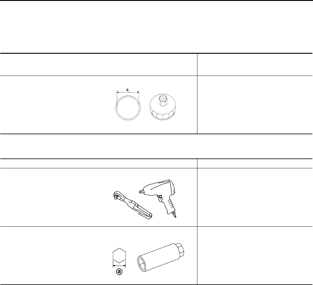
Tool number
(Kent-Moore No.)
Tool name
Description
KV10115801
(J-38956)
Oil filter wrench
Removing and installing oil filter
a: 64.3 mm (2.531 in)
S-NT375
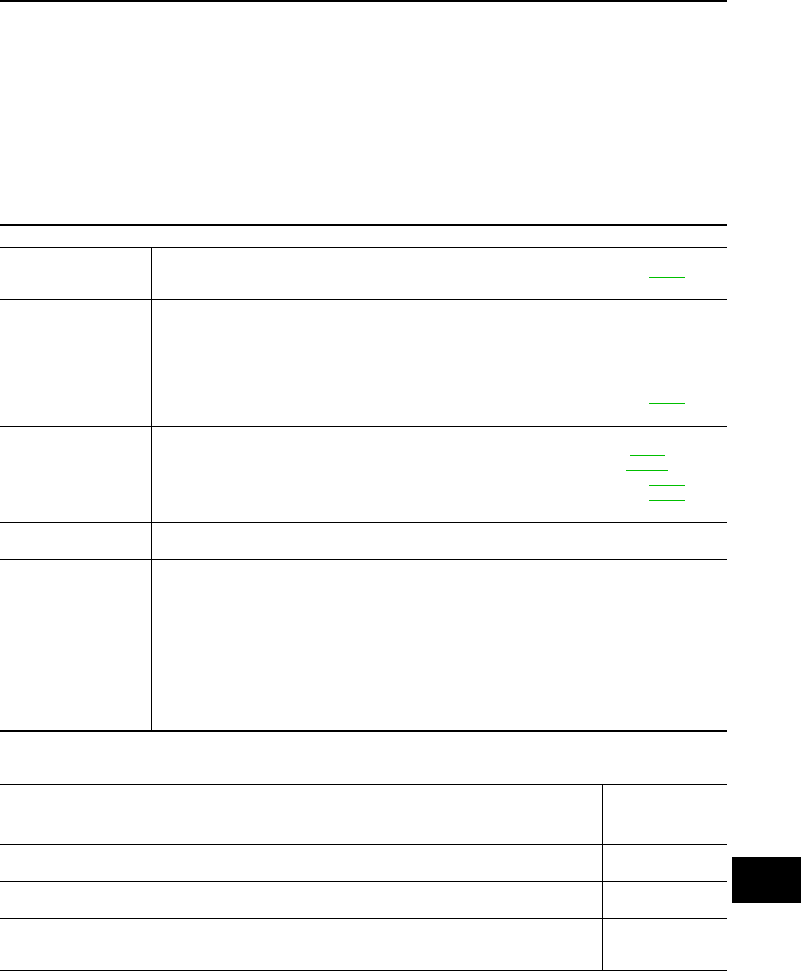
Tool name Description
Power tool Loosening nuts and bolts
Spark plug wrench Removing and installing spark plug
a : 14 mm (0.55 in)
PBIC0190E
JPBIA0399ZZ
Revision: 2013 February 2012 G Sedan
GENERAL MAINTENANCE
MA-5
< PERIODIC MAINTENANCE >
C
D
E
F
G
H
I
J
K
L
M
B
MA
N
O
A
PERIODIC MAINTENANCE
GENERAL MAINTENANCE
FOR NORTH AMERICA
FOR NORTH AMERICA : Explanation of General Maintenance INFOID:0000000007466276
General maintenance includes those items which should be checked during the normal day-to-day operation
of the vehicle. They are essential if the vehicle is to continue operating properly. The owners can perform
checks and inspections themselves or have their INFINITI dealers do them.
OUTSIDE THE VEHICLE
The maintenance items listed here should be performed from time to time, unless otherwise specified.
INSIDE THE VEHICLE
The maintenance items listed here should be checked on a regular basis, such as when performing periodic maintenance, cleaning the vehicle,
etc.
Item Reference page
Tires Check the pressure with a gauge often and always prior to long distance trips. Ad-
just the pressure in all tires, including the spare, to the pressure specified. Check
carefully for damage, cuts or excessive wear.
WT-49
Wheel nuts When checking the tires, make sure no nuts are missing, and check for any loose
nuts. Tighten if necessary. —
Tire rotation Tires should be rotated every 7,500 miles (12,000 km). If the vehicle is equipped
with different sized tires in the front and rear, tires cannot be rotated. MA-49
Tire Pressure Monitor-
ing System (TPMS)
transmitter components
Replace the TPMS transmitter grommet seal, valve core and cap when the tires are
replaced due to wear or age. WT-46
Wheel alignment and
balance If the vehicle should pull to either side while driving on a straight and level road, or
if you detect uneven or abnormal tire wear, there may be a need for wheel align-
ment. If the steering wheel or seat vibrates at normal highway speeds, wheel bal-
ancing may be needed. For additional information regarding tires, refer to
″lmportant Tire Safety Information″ (US) or ″Tire Safety Information″ (Canada) in
the INFINITI Warranty Information Booklet.
FSU-7 (2WD)
FSU-29 (AWD)
RSU-8
MA-49
Windshield Clean the windshield on a regular basis. Check the windshield at least every six
months for cracks or other damage. Repair as necessary. —
Windshield wiper
blades Check for cracks or wear if they do not wipe properly. —
Doors and engine hood Check that all doors and the engine hood operate properly. Also make sure that all
latches lock securely. Lubricate if necessary. Make sure that the secondary latch
keeps the hood from opening when the primary latch is released.
When driving in areas using road salt or other corrosive materials, check lubrication
frequently.
MA-56
Lamps Make sure that the headlamps, stop lamps, tail lamps, turn signal lamps, and other
lamps are all operating properly and installed securely. Also check headlamp aim.
Clean the headlamps on a regular basis. —
Item Reference page
Warning lamps and
chimes Make sure that all warning lamps and chimes are operating properly. —
Windshield wiper and
washer Check that the wipers and washer operate properly and that the wipers do not
streak. —
Windshield defroster Check that the air comes out of the defroster outlets properly and in sufficient quan-
tity when operating the heater or air conditioner. —
Steering wheel Check that it has the specified play. Check for changes in the steering condition,
such as excessive play, hard steering or strange noises.
Free play: Less than 35 mm (1.38 in) —
Revision: 2013 February 2012 G Sedan
MA-6
< PERIODIC MAINTENANCE >
GENERAL MAINTENANCE
UNDER THE HOOD AND VEHICLE
The maintenance items listed here should be checked periodically (e.g. each time you check the engine oil or refuel).
FOR MEXICO
Seats Check seat position controls such as seat adjusters, seatback recliner, etc. to make
sure they operate smoothly and that all latches lock securely in every position.
Check that the head restrains move up and down smoothly and that the locks (if
equipped) hold securely in all latched positions. Check that the latches lock secure-
ly for folding-down rear seatbacks.
—
Seat belts Check that all parts of the seat belt system (e.g. buckles, anchors, adjusters and
retractors) operate properly and smoothly, and are installed securely. Check the
belt webbing for cuts, fraying, wear or damage.
MA-56
Accelerator pedal Check the pedal for smooth operation and make sure the pedal does not catch or
require uneven effort. Keep the floor mats away from the pedal. —
Brakes Check that the brake does not pull the vehicle to one side when applied. —
Brake pedal and booster Check the pedal for smooth operation and make sure it has the proper distance un-
der it when depressed fully. Check the brake booster function. Be sure to keep the
floor mats away from the pedal.
BR-7
BR-13
Clutch pedal Make sure the pedal operates smoothly and check that it has the proper free play. CL-6
Parking brake Check that the lever or pedal has the proper travel and make sure that the vehicle
is held securely on a fairly steep hill when only the parking brake is applied. PB-3 (PEDAL TYPE)
PB-4 (LEVER TYPE)
Automatic transmission
"Park" mechanism Check that the lock release button on the selector lever operates properly and
smoothly. On a fairly steep hill check that the vehicle is held securely with the se-
lector lever in the P (Park) position without applying any brakes.
—
Item Reference page
Item Reference page
Windshield washer fluid Check that there is adequate fluid in the tank. —
Engine coolant level Check the coolant level when the engine is cold. CO-9
Radiator and hoses Check the front of the radiator and clean off any dirt, insects, leaves, etc., that may
have accumulated. Make sure the hoses have no cracks, deformation, deterioration
or loose connections. —
Brake and clutch fluid
levels Make sure that the brake and clutch fluid levels are between the “MAX” and “MIN”
lines on the reservoir(s).
MA-51
MA-42
Battery Check the fluid level in each cell. It should be between the “MAX” and “MIN” lines.
Vehicles operated in high temperatures or under severe conditions require frequent
checks of the battery fluid level. PG-3
Engine drive belts Make sure that no belt is frayed, worn, cracked or oily. MA-22(VQ37VHR)
MA-31(VQ25HR)
Engine oil level Check the level on the oil level gauge after parking the vehicle on a level spot and
turning off the engine. LU-9
Power steering fluid lev-
el and lines Check the level on the dipstick with the engine off. Check the lines for improper at-
tachment, leaks, cracks, etc. MA-54
Exhaust system Make sure there are no loose supports, cracks or holes. If the sound of the exhaust
seems unusual or there is a smell of exhaust fumes, immediately locate the trouble
and correct it.
MA-41
Underbody The underbody is frequently exposed to corrosive substances such as those used
on icy roads or to control dust. It is very important to remove these substances, oth-
erwise rust will form on the floor pan, frame, fuel lines and around the exhaust sys-
tem. At the end of winter, the underbody should be thoroughly flushed with plain
water, being careful to clean those areas where mud and dirt can easily accumulate.
—
Fluid leaks Check under the vehicle for fuel, oil, water or other fluid leaks after the vehicle has
been parked for a while. Water dripping from the air conditioner after use is normal.
If you should notice any leaks or gasoline fumes are evident, check for the cause
and correct it immediately.
—
Revision: 2013 February 2012 G Sedan
GENERAL MAINTENANCE
MA-7
< PERIODIC MAINTENANCE >
C
D
E
F
G
H
I
J
K
L
M
B
MA
N
O
A
FOR MEXICO : General Maintenance INFOID:0000000007793834
General maintenance includes those items which should be checked during the normal day-to-day operation
of the vehicle. They are essential if the vehicle is to continue operating properly. The owners can perform the
checks and inspections themselves or they can have their INFINITI dealers do them.
OUTSIDE THE VEHICLE
The maintenance items listed here should be performed from time to time, unless otherwise specified.
INSIDE THE VEHICLE
The maintenance items listed here should be checked on a regular basis, such as when performing periodic maintenance, cleaning the vehicle,
etc.
UNDER THE HOOD AND VEHICLE
The maintenance items listed here should be checked periodically (e.g. each time you check the engine oil or refuel).
Item Reference page
Lamps Clean the head lamps on a regular basis. Make sure that the headlamps, stop
lamps, tail lamps, turn signal lamps, and other lamps are all operating properly
and installed securely. Also check the aim of the headlamps.
—
Tires Check the pressure with a gauge often and always prior to long distance trips.
Adjust the pressure in all tires, including the spare, to the pressure specified.
Check carefully for damage, cuts or excessive wear. WT-49
Wiper blades Check for cracks or wear if not functioning correctly. —
Doors and engine
hood Check that all doors and the engine hood operate properly. Also make sure that
all latches lock securely. Lubricate if necessary. Make sure that the secondary
latch keeps the hood from opening when the primary latch is released. When
driving in areas using road salt or other corrosive materials, check for lubrication
frequently.
MA-56
Tire rotation Tires should be rotated every 10,000 km (6,000 miles). MA-49
Tire Pressure Monitor-
ing System (TPMS)
transmitter compo-
nents (if equipped)
Replace the TPMS transmitter grommet seal, valve core and cap when the tires
are replaced due to wear or age. WT-46
Windshield Clean the windshield on a regular basis. Check the windshield at least every six
months for cracks or other damage. Repair as necessary. —
Item Reference page
Accelerator pedal Check the pedal for smooth operation and make sure that the pedal does not
catch or require uneven effort. Keep the floor mats away from the pedal. —
Brake pedal Check the pedal for smooth operation and make sure that it has the proper dis-
tance under it when depressed fully. Check the brake booster function. Be sure
to keep the floor mats away from the pedal.
BR-7
Parking brake Check that the lever or the pedal has the proper travel and make sure that the
vehicle is held securely on a fairly steep hill when only the parking brake is ap-
plied.
PB-3 (PEDAL TYPE)
PB-4 (LEVER TYPE)
Warning lamps and
chimes Make sure that all warning lamps and chimes are operating properly. —
Windshield defogger Check that the air comes out of the defogger outlets properly and in good quantity
when operating the heater or air conditioner. —
Windshield wiper and
washer Check that the wipers and washer operate properly and that the wipers do not
streak. —
Steering wheel Check that it has the specified play.
Check for changes in the steering conditions, such as excessive free play, hard
steering or strange noises.
Free play: Less than 35 mm (1.38 in)
—
Seat belts Check that all parts of the seat belt system (e.g. buckles, anchors, adjusters and
retractors) operate properly and smoothly, and are installed securely. Check the
belt webbing for cuts, fraying, wear or damage. MA-56
Revision: 2013 February 2012 G Sedan
MA-8
< PERIODIC MAINTENANCE >
GENERAL MAINTENANCE
Item Reference page
Windshield washer
fluid Check that there is adequate fluid in the tank. —
Engine coolant level Check the coolant level when the engine is cold. CO-9
Engine drive belts Make sure that drive belts are not frayed, worn, cracked or oily. MA-22(VQ37VHR)
MA-31(VQ25HR)
Engine oil level Check the level after parking the vehicle (on a level ground) and turning off the
engine. LU-9
Brake fluid level Make sure that the brake fluid level is between the “MAX” and “MIN” lines on the
reservoirs. MA-51
Battery Check the fluid level in each cell. It should be between the “MAX” and “MIN” lines.
Vehicles operated in high temperatures or under severe conditions require fre-
quent checks of the battery fluid level.
PG-3
Fluid leaks Check under the vehicle for fuel, oil, water or other fluid leaks after the vehicle
has been parked for a while. Water dripping from the air conditioner after use is
normal. If you should notice any leaks or if fuel fumes are evident, check for
cause and have it corrected immediately.
—
Power steering fluid
level and lines Check the level when the fluid is cold, with the engine off. check the lines for
proper attachment, leaks, cracks, etc.. MA-54
Revision: 2013 February 2012 G Sedan
PERIODIC MAINTENANCE
MA-9
< PERIODIC MAINTENANCE >
C
D
E
F
G
H
I
J
K
L
M
B
MA
N
O
A
PERIODIC MAINTENANCE
FOR NORTH AMERICA
FOR NORTH AMERICA : Introduction of Periodic Maintenance INFOID:0000000007466277
Two different maintenance schedules are provided, and should be used, depending upon the conditions in
which the vehicle is mainly operated. After 60,000 miles (96,000 km) or 48 months, continue the periodic
maintenance at the same mileage/time intervals.
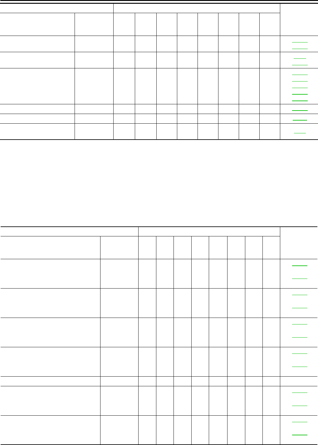
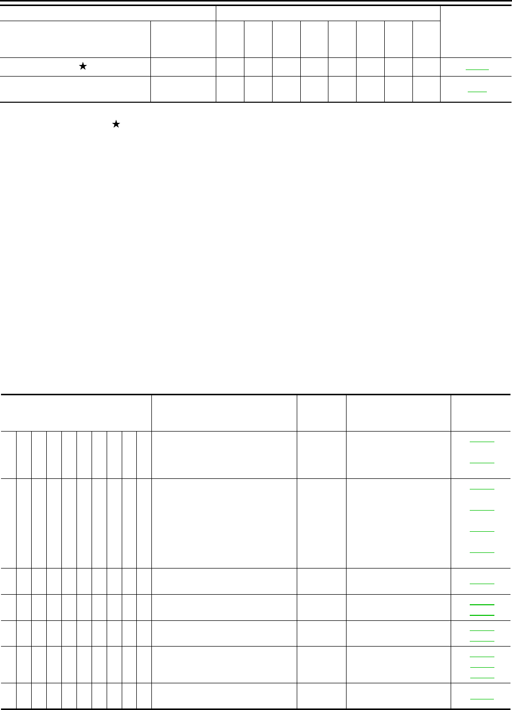
FOR NORTH AMERICA : Schedule 1 INFOID:0000000007466278
EMISSION CONTROL SYSTEM
Abbreviations: R = Replace. I = Inspect. Correct or replace if necessary. [ ]: At the mileage intervals only
Schedule 1
Follow Periodic Maintenance Schedule 1 if the driving habits frequently include
one or more of the following driving conditions:
• Repeated short trips of less than 5 miles (8 km).
• Repeated short trips of less than 10 miles (16 km) with outside temperatures
remaining below freezing.
• Operating in hot weather in stop-and-go “rush hour” traffic.
• Extensive idling and/or low speed driving for long distances, such as police, taxi
or door-to-door delivery use.
• Driving in dusty conditions.
• Driving on rough, muddy, or salt spread roads.
• Towing a trailer, using a camper or a car-top carrier.
Emission Control Sys-
tem Maintenance
MA-9
Chassis and Body
Maintenance
Schedule 2 Follow Periodic Maintenance Schedule 2 if none of driving conditions shown in
Schedule 1 apply to the driving habits.
Emission Control Sys-
tem Maintenance MA-12
Chassis and Body
Maintenance
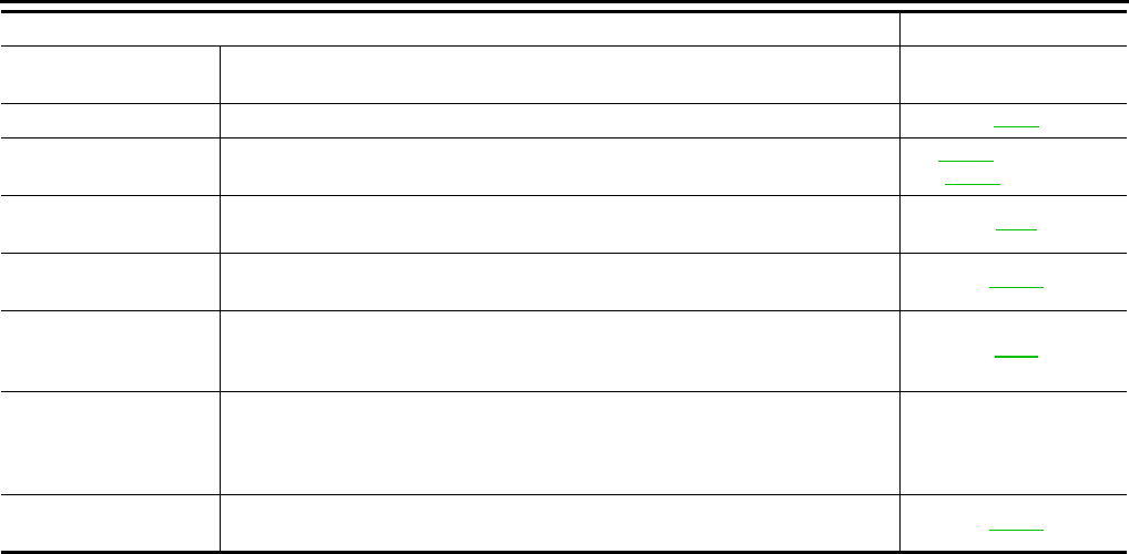
MAINTENANCE OPERATION MAINTENANCE INTERVAL Reference
Section -
Page or -
Content Title
Perform at number of miles,
kilometers or months, which-
ever comes first.
Miles x 1,000
(km x 1,000)
Months
3.75
(6)
3
7.50
(12)
6
11.25
(18)
9
15
(24)
12
18.75
(30)
15
22.5
(36)
18
26.25
(42)
21
30
(48)
24
Drive belts NOTE (1)
MA-22
(VQ37VHR)
MA-31
(VQ25HR)
Air cleaner filter NOTE (2) [R]
MA-26
(VQ37VHR)
MA-36
(VQ25HR)
EVAP vapor lines I*
MA-30
(VQ37VHR)
MA-40
(VQ25HR)
Fuel lines I*
MA-26
(VQ37VHR)
MA-36
(VQ25HR)
Fuel filter NOTE (3) —
Engine coolant* NOTE (4)
MA-22
(VQ37VHR)
MA-32
(VQ25HR)
Engine oil R R R R R R R R
MA-26
(VQ37VHR)
MA-36
(VQ25HR)
Revision: 2013 February 2012 G Sedan
MA-10
< PERIODIC MAINTENANCE >
PERIODIC MAINTENANCE
NOTE:
Engine oil filter (Use genuine
NISSAN engine oil filter or
equivalent.)
R RRRRRRR
MA-27
(VQ37VHR)
MA-37
(VQ25HR)
Spark plugs (Iridium-tipped
type) Replace every 105,000 miles (168,000 km).
MA-29
(VQ37VHR)
MA-39
(VQ25HR)
Intake & exhaust valve clear-
ance* NOTE (5)
EM-12
(VQ25HR)
EM-163
(VQ37VHR)
MAINTENANCE OPERATION MAINTENANCE INTERVAL Reference
Section -
Page or -
Content Title
Perform at number of miles,
kilometers or months, which-
ever comes first.
Miles x 1,000
(km x 1,000)
Months
3.75
(6)
3
7.50
(12)
6
11.25
(18)
9
15
(24)
12
18.75
(30)
15
22.5
(36)
18
26.25
(42)
21
30
(48)
24
MAINTENANCE OPERATION MAINTENANCE INTERVAL Reference
Section -
Page or -
Content Title
Perform at number of miles,
kilometers or months, which-
ever comes first.
Miles x 1,000
(km x 1,000)
Months
33.75
(54)
27
37.5
(60)
30
41.25
(66)
33
45
(72)
36
48.75
(78)
39
52.5
(84)
42
56.25
(90)
45
60
(96)
48
Drive belts NOTE (1) I*
MA-22
(VQ37VHR)
MA-31
(VQ25HR)
Air cleaner filter NOTE (2) [R]
MA-26
(VQ37VHR)
MA-36
(VQ25HR)
EVAP vapor lines I*
MA-30
(VQ37VHR)
MA-40
(VQ25HR)
Fuel lines I*
MA-26
(VQ37VHR)
MA-36
(VQ25HR)
Fuel filter NOTE (3) —
Engine coolant* NOTE (4)
MA-22
(VQ37VHR)
MA-32
(VQ25HR)
Engine oil R R R R R R R R
MA-26
(VQ37VHR)
MA-36
(VQ25HR)
Engine oil filter (Use genuine
NISSAN engine oil filter or
equivalent.) R RRRRRRR
MA-27
(VQ37VHR)
MA-37
(VQ25HR)
Spark plugs (Iridium-tipped
type) Replace every 105,000 miles (168,000 km).
MA-29
(VQ37VHR)
MA-39
(VQ25HR)
Intake & exhaust valve clear-
ance* NOTE (5)
EM-12
(VQ25HR)
EM-163
(VQ37VHR)
Revision: 2013 February 2012 G Sedan
PERIODIC MAINTENANCE
MA-11
< PERIODIC MAINTENANCE >
C
D
E
F
G
H
I
J
K
L
M
B
MA
N
O
A
(1) After 60,000 miles (96,000 km) or 48 months, inspect every 15,000 miles (24,000 km) or 12 months. Replace the drive belts if found
damaged or if the auto belt tensioner reading reaches the maximum limit. (If auto belt tensioner is equipped)
(2) If operating mainly in dusty conditions, more frequent maintenance may be required.
(3) Maintenance-free item. For service procedures, refer to FL section.
(4) First replacement intervals 105,000 miles (168,000 km) or 84 months. After first replacement, replace every 75,000 miles (120,000
km) or 60 months. Use only Genuine NISSAN Long Life Antifreeze / Coolant (blue) or equivalent with proper mixture ratio of 50% anti-
freeze and 50% demineralized or distilled water. Mixing any other type of coolant or the use of non-distilled water will reduce the life
expectancy of the factory-fill coolant.
(5) Periodic maintenance is not required. However, if valve noise increases, inspect valve clearance.
* Maintenance items and intervals with “*” are recommended by INFINITI for reliable vehicle operation. The owner need not perform
such maintenance in order to maintain the emission warranty or manufacturer recall liability. Other maintenance items and intervals are
required.
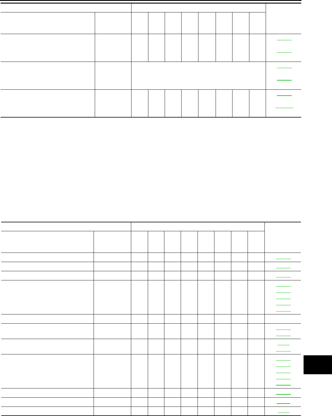
CHASSIS AND BODY
Abbreviations: R = Replace. I = Inspect. Correct or replace if necessary.
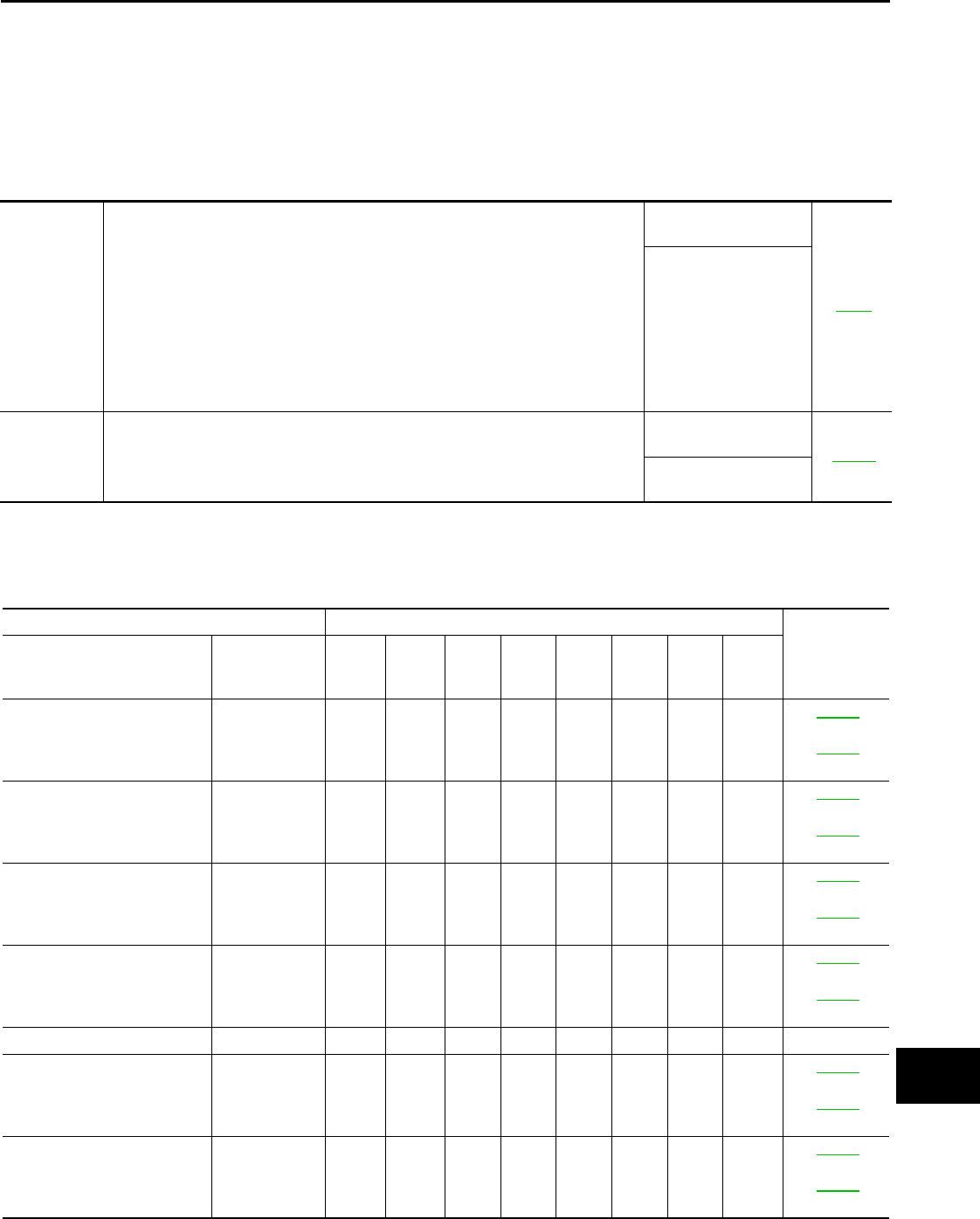
MAINTENANCE OPERATION MAINTENANCE INTERVAL Reference
Section -
Page or -
Content Title
Perform at number of miles,
kilometers or months, which-
ever comes first.
Miles x 1,000
(km x 1,000)
Months
3.75
(6)
3
7.50
(12)
6
11.25
(18)
9
15
(24)
12
18.75
(30)
15
22.5
(36)
18
26.25
(42)
21
30
(48)
24
Brake lines & cables I I MA-52
Brake pads & rotors I I I I MA-52
Brake fluid R R MA-52
Manual transmission gear oil,
transfer fluid & differential
gear oil
NOTE (1) I I
MA-41
MA-42
MA-46
MA-47
MA-48
Automatic transmission fluid NOTE (2) —
Steering gear & linkage, axle
& suspension parts IIII
MA-53
MA-54
Tire rotation NOTE (3) MA-5
MA-49
Drive shaft boots and propel-
ler shaft (AWD models) IIII
MA-55
MA-43
MA-44
MA-45
MA-45
Exhaust system I I I I MA-41
In-cabin microfilter R R VTL-8
Stop lamp switch & ASCD
brake switch NOTE (4) I I BR-7
MAINTENANCE OPERATION MAINTENANCE INTERVAL Reference
Section -
Page or -
Content Title
Perform at number of miles,
kilometers or months, which-
ever comes first.
Miles x 1,000
(km x 1,000)
Months
33.75
(54)
27
37.5
(60)
30
41.25
(66)
33
45
(72)
36
48.75
(78)
39
52.5
(84)
42
56.25
(90)
45
60
(96)
48
Brake lines & cables I I MA-52
Brake pads & rotors I I I I MA-52
Brake fluid R R MA-52
Manual transmission gear oil,
transfer fluid & differential
gear oil
NOTE (1) I I
MA-41
MA-42
MA-46
MA-47
MA-48
Automatic transmission fluid NOTE (2) —
Revision: 2013 February 2012 G Sedan
MA-12
< PERIODIC MAINTENANCE >
PERIODIC MAINTENANCE
NOTE:
(1) If towing a trailer, using a camper or a car-top carrier, or driving on rough or muddy roads, change (not just inspect) fluid /oil at every
30,000 miles (48,000 km) or 24 months.
(2) Automatic transmission fluid is maintenance-free.
(3) Refer to “Tire rotation” under the “General maintenance” heading earlier in this section.
(4) Inspect the clearance between the brake pedal and the switches.
FOR NORTH AMERICA : Schedule 2 INFOID:0000000007466279
EMISSION CONTROL SYSTEM
Abbreviations: R = Replace. I = Inspect. Correct or replace if necessary. [ ]: At the mileage intervals only
Steering gear & linkage, axle
& suspension parts IIII
MA-53
MA-54
Tire rotation NOTE (3) MA-5
MA-49
Drive shaft boots and propel-
ler shaft (AWD models) IIII
MA-55
MA-43
MA-44
MA-45
MA-45
Exhaust system I I I I MA-41
In-cabin microfilter R R VTL-8
Stop lamp switch & ASCD
brake switch NOTE (4) I I BR-7
MAINTENANCE OPERATION MAINTENANCE INTERVAL Reference
Section -
Page or -
Content Title
Perform at number of miles,
kilometers or months, which-
ever comes first.
Miles x 1,000
(km x 1,000)
Months
33.75
(54)
27
37.5
(60)
30
41.25
(66)
33
45
(72)
36
48.75
(78)
39
52.5
(84)
42
56.25
(90)
45
60
(96)
48
MAINTENANCE OPERATION MAINTENANCE INTERVAL Reference
Section -
Page or -
Content Title
Perform at number of miles, kilometers
or months, whichever comes first.
Miles x 1,000
(km x 1,000)
Months
7.5
(12)
6
15
(24)
12
22.5
(36)
18
30
(48)
24
37.5
(60)
30
45
(72)
36
52.5
(84)
42
60
(96)
48
Drive belts NOTE (1) I*
MA-22
(VQ37VHR)
MA-31
(VQ25HR)
Air cleaner filter [R] [R]
MA-26
(VQ37VHR)
MA-36
(VQ25HR)
EVAP vapor lines I* I*
MA-30
(VQ37VHR)
MA-40
(VQ25HR)
Fuel lines I* I*
MA-26
(VQ37VHR)
MA-36
(VQ25HR)
Fuel filter NOTE (2) —
Engine coolant* NOTE (3)
MA-22
(VQ37VHR)
MA-32
(VQ25HR)
Engine oil R R R R R R R R
MA-26
(VQ37VHR)
MA-36
(VQ25HR)
Revision: 2013 February 2012 G Sedan
PERIODIC MAINTENANCE
MA-13
< PERIODIC MAINTENANCE >
C
D
E
F
G
H
I
J
K
L
M
B
MA
N
O
A
NOTE:
(1) After 60,000 miles (96,000 km) or 48 months, inspect every 15,000 miles (24,000 km) or 12 months. Replace the drive belts if found
damaged or if the auto belt tensioner reading reaches the maximum limit. (If auto belt tensioner is equipped)
(2) Maintenance-free item. For service procedures, refer to FL section.
(3) First replacement intervals 105,000 miles (168,000 km) or 84 months. After first replacement, replace every 75,000 miles (120,000
km) or 60 months. Use only Genuine NISSAN Long Life Antifreeze / Coolant (blue) or equivalent with proper mixture ratio of 50% anti-
freeze and 50% demineralized or distilled water. Mixing any other type of coolant or the use of non-distilled water will reduce the life
expectancy of the factory-fill coolant.
(4) Periodic maintenance is not required. However, if valve noise increases, inspect valve clearance.
* Maintenance items and intervals with “*” are recommended by INFINITI for reliable vehicle operation. The owner need not perform
such maintenance in order to maintain the emission warranty or manufacturer recall liability. Other maintenance items and intervals are
required.
CHASSIS AND BODY
Abbreviations: R = Replace. I = Inspect. Correct or replace if necessary.
Engine oil filter (Use genuine NISSAN
engine oil filter or equivalent.) RRRRRRRR
MA-27
(VQ37VHR)
MA-37
(VQ25HR)
Spark plugs (Iridium-tipped type) Replace every 105,000 miles (168,000 km).
MA-29
(VQ37VHR)
MA-39
(VQ25HR)
Intake & exhaust valve clearance* NOTE (4)
EM-12
(VQ25HR)
EM-163
(VQ37VHR)
MAINTENANCE OPERATION MAINTENANCE INTERVAL Reference
Section -
Page or -
Content Title
Perform at number of miles, kilometers
or months, whichever comes first.
Miles x 1,000
(km x 1,000)
Months
7.5
(12)
6
15
(24)
12
22.5
(36)
18
30
(48)
24
37.5
(60)
30
45
(72)
36
52.5
(84)
42
60
(96)
48
MAINTENANCE OPERATION MAINTENANCE INTERVAL Reference
Section -
Page or -
Content Title
Perform at number of miles, kilometers
or months, whichever comes first.
Miles x 1,000
(km x 1,000)
Months
7.5
(12)
6
15
(24)
12
22.5
(36)
18
30
(48)
24
37.5
(60)
30
45
(72)
36
52.5
(84)
42
60
(96)
48
Brake lines & cables I I I I MA-52
Brake pads & rotors I I I I MA-52
Brake fluid R R MA-52
Manual transmission gear oil, transfer
fluid & differential gear oil IIII
MA-41
MA-42
MA-46
MA-47
MA-48
Automatic transmission fluid NOTE (1) —
Steering gear & linkage, axle & suspen-
sion parts II
MA-53
MA-54
Tire rotation NOTE (2) MA-5
MA-49
Drive shaft boots and propeller shaft
(AWD models) IIII
MA-55
MA-43
MA-44
MA-45
MA-45
Exhaust system I I MA-41
In-cabin microfilter R R R R VTL-8
Stop lamp switch & ASCD brake switch NOTE (3) I I I I BR-7
Revision: 2013 February 2012 G Sedan
MA-14
< PERIODIC MAINTENANCE >
PERIODIC MAINTENANCE
NOTE:
(1) Automatic transmission fluid is maintenance-free.
(2) Refer to “Tire rotation” under the “General maintenance” heading earlier in this section.
(3) Inspect the clearance between the brake pedal and the switches.
FOR MEXICO
FOR MEXICO : Periodic Maintenance INFOID:0000000007793835
The following tables show the normal maintenance schedule. Depending upon weather and atmospheric con-
ditions, varying road surfaces, individual driving habits and vehicle usage, additional or more frequent mainte-
nance may be required.
Periodic maintenance beyond the last period shown on the tables requires similar maintenance.
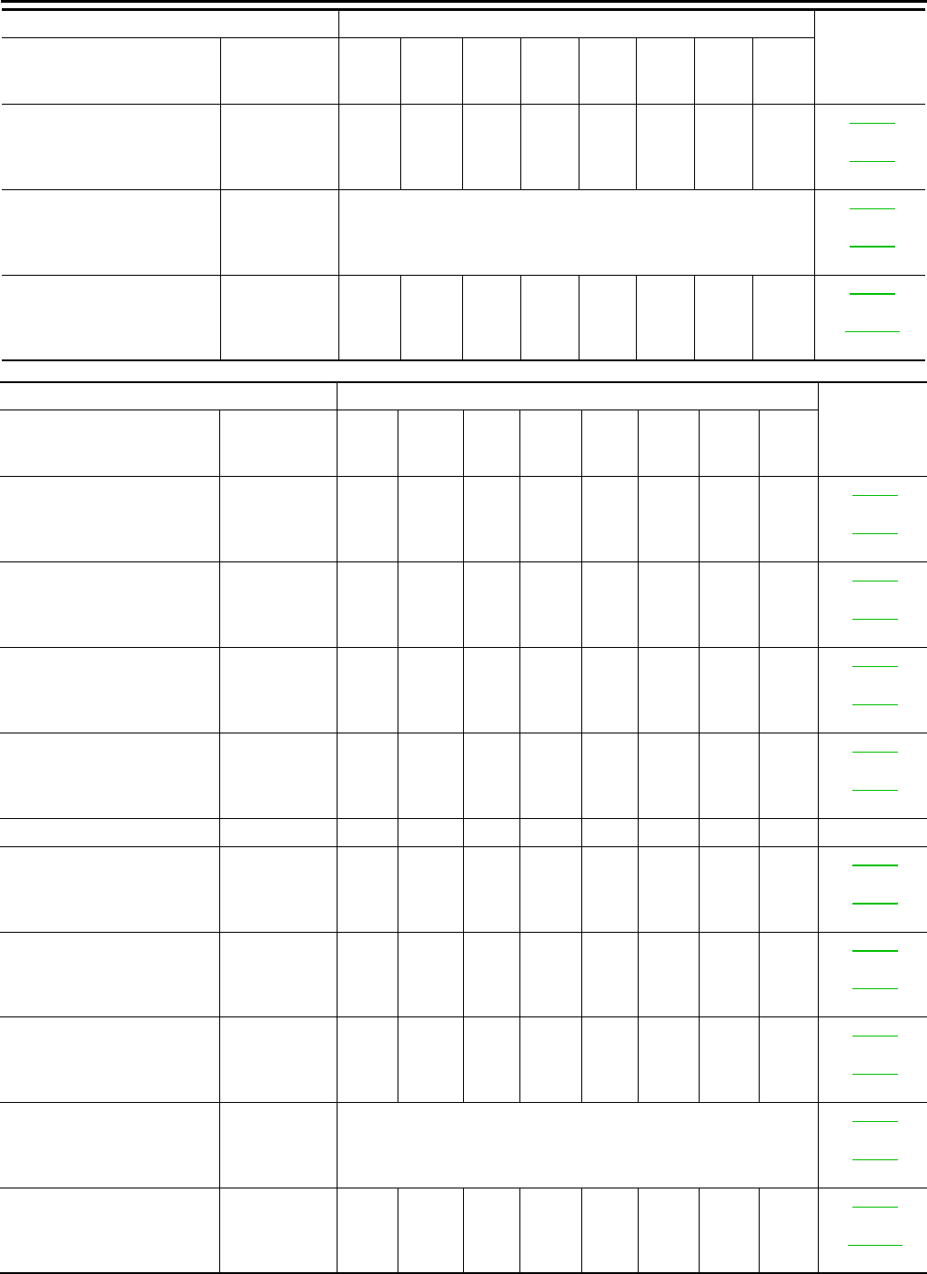
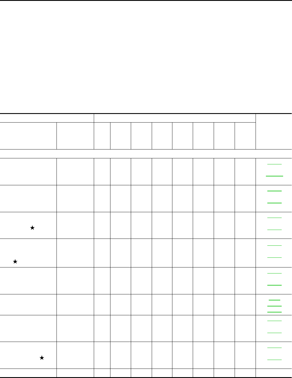
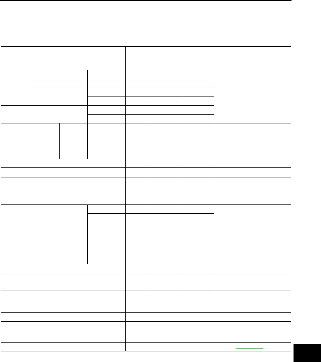
ENGINE AND EMISSION CONTROL MAINTENANCE
Abbreviations: I = Inspect and correct or replace as necessary, R = Replace, E = Check and correct the engine coolant mixture ratio.
MAINTENANCE OPERATION MAINTENANCE INTERVAL
Reference
page
Perform at a kilometers
(miles) or month inter-
val, whichever comes
first.
km × 1,000
(Miles × 1,000)
Months
10
(6)
6
20
(12)
12
30
(18)
18
40
(24)
24
50
(30)
30
60
(36)
36
70
(42)
42
80
(48)
48
Underhood and under vehicle
Intake & exhaust valve
clearance See NOTE (1)
EM-12
(VQ25HR)
EM-163
(VQ37VHR)
Drive belt See NOTE (2) I I
MA-22
(VQ37VHR)
MA-31
(VQ25HR)
Engine oil (Use recom-
mended oil.) RRRRRRRR
MA-26
(VQ37VHR)
MA-36
(VQ25HR)
Engine oil filter (Use
genuine NISSAN en-
gine oil filter or equiva-
lent)
RRRRRRRR
MA-27
(VQ37VHR)
MA-37
(VQ25HR)
Engine coolant (Use
Genuine NISSAN En-
gine Coolant or equiva-
lent in its quality.)
See NOTE (3) E R
MA-22
(VQ37VHR)
MA-32
(VQ25HR)
Cooling system I I
CO-9
CO-13
CO-13
Fuel lines I I
MA-26
(VQ37VHR)
MA-36
(VQ25HR)
Air cleaner filter (Vis-
cous paper type) RR
MA-26
(VQ37VHR)
MA-36
(VQ25HR)
Fuel filter (In-tank type) See NOTE (4) —
Revision: 2013 February 2012 G Sedan
PERIODIC MAINTENANCE
MA-15
< PERIODIC MAINTENANCE >
C
D
E
F
G
H
I
J
K
L
M
B
MA
N
O
A
NOTE:
•Maintenance items with “ ” should be performed more frequently according to “Maintenance Under Severe Driving Condi-
tions”.
• (1) Periodic maintenance is not required. However, if valve noise increases, check valve clearance.
• (2) Replace the drive belts if found damaged or if the auto belt tensioner reading reaches the maximum limit. (If auto belt tensioner is
equipped)
• (3) Use Genuine NISSAN Engine Coolant or equivalent in its quality, in order to avoid possible aluminum corrosion within the engine
cooling system caused by the use of non-genuine engine coolant. After first replacement, replace every 40,000 km (24,000 miles) or
24 months.
• (4) Maintenance-free item.
• (5) Replace spark plug when the spark plug gap exceeds 1.4 mm (0.055 in) even if within specified periodic replacement mileage.
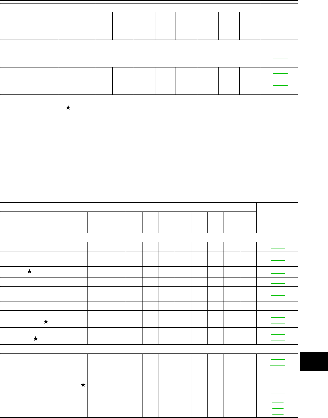
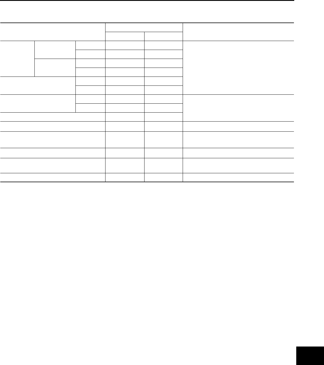
CHASSIS AND BODY MAINTENANCE
Abbreviations: I = Inspect and correct or replace as necessary, R = Replace
Spark plugs (Iridium-
tipped type) See NOTE (5) Replace every 100,000 km (60,000 miles)
MA-29
(VQ37VHR)
MA-39
(VQ25HR)
EVAP vapor lines (With
carbon canister) II
MA-30
(VQ37VHR)
MA-40
(VQ25HR)
MAINTENANCE OPERATION MAINTENANCE INTERVAL
Reference
page
Perform at a kilometers
(miles) or month inter-
val, whichever comes
first.
km × 1,000
(Miles × 1,000)
Months
10
(6)
6
20
(12)
12
30
(18)
18
40
(24)
24
50
(30)
30
60
(36)
36
70
(42)
42
80
(48)
48
MAINTENANCE OPERATION MAINTENANCE INTERVAL
Reference page
Perform at a kilometers (miles) or
month interval, whichever comes first.
km × 1,000
(Miles × 1,000)
Months
10
(6)
6
20
(12)
12
30
(18)
18
40
(24)
24
50
(30)
30
60
(36)
36
70
(42)
42
80
(48)
48
Underhood and under vehicle
Brake line & cables I I I I MA-52
Brake fluid
(For level & leaks) IIIIMA-51
Brake fluid RRMA-52
Exhaust system I I MA-41
Power steering fluid & lines
(For level & leaks) IIIIMA-54
Automatic transmission fluid See NOTE (1) —
Differential gear oil
(For level & leaks) IIII
MA-47
MA-48
Steering gear & linkage, axle & sus-
pension parts II
MA-53
MA-54
Outside and inside
Wheel alignment
(If necessary, balance wheels) IIII
FSU-7
RSU-8
MA-49
Brake pads, rotors, drums & linings IIII
MA-52
BR-14
BR-16
Foot brake & parking brake
(For free play, stroke & operation) IIII
BR-7
PB-3
PB-4
Revision: 2013 February 2012 G Sedan
MA-16
< PERIODIC MAINTENANCE >
PERIODIC MAINTENANCE
NOTE:
•Maintenance items with “ ” should be performed more frequently according to “Maintenance Under Severe Driving Condi-
tions”.
• (1) Automatic transmission fluid is maintenance-free.
• (2) Inspect the clearance between the brake pedal and the switches.
MAINTENANCE UNDER SEVERE DRIVING CONDITIONS
The maintenance intervals shown on the preceding pages are for normal operating conditions. If the vehicle is
mainly operated under severe driving conditions as shown below, more frequent maintenance must be per-
formed on the following items as shown in the table.
Severe driving conditions
A — Driving under dusty conditions
B — Driving repeatedly short distances
C — Towing a trailer or caravan
D — Extensive idling
E —Driving in extremely adverse weather conditions or in areas where ambient temperatures are either
extremely low or extremely high
F — Driving in high humidity or mountainous areas
G — Driving in areas using salt or other corrosive areas
H — Driving on rough and/or muddy roads or in the desert
I — Driving with frequent use of braking or in mountainous areas
J — Frequent driving in water
Maintenance operation: Inspect = Check and correct or replace as necessary.
Air conditioner filter RRRRVTL-8
Stop lamp switch & ASCD brake
switch See NOTE (2)IIIIBR-7
MAINTENANCE OPERATION MAINTENANCE INTERVAL
Reference page
Perform at a kilometers (miles) or
month interval, whichever comes first.
km × 1,000
(Miles × 1,000)
Months
10
(6)
6
20
(12)
12
30
(18)
18
40
(24)
24
50
(30)
30
60
(36)
36
70
(42)
42
80
(48)
48
Driving condition Maintenance item
Mainte-
nance op-
eration
Maintenance interval Reference
page
A.........
Air cleaner filter
(Viscous paper type) Replace More frequently
MA-26
(VQ37VHR)
MA-36
(VQ25HR)
ABCD......Engine oil & engine oil filter Replace Every 5,000 km (3,000
miles) or 3 months
MA-26
(VQ37VHR)
MA-36
(VQ25HR)
MA-27
(VQ37VHR)
MA-37
(VQ25HR)
.....F....Brake fluid Replace Every 20,000 km (12,000
miles) or 12 months MA-52
..C....H..Differential gear oil Replace Every 40,000 km (24,000
miles) or 24 months
MA-47
MA-48
......GH..Steering gear & linkage, axle & sus-
pension parts Inspect Every 20,000 km (12,000
miles) or 12 months MA-53
MA-54
A. C. . . GHI . Brake pads, rotors, drums & linings Inspect Every 10,000 km (6,000
miles) or 6 months
MA-52
BR-14
BR-16
A.........Air conditioner filter Replace More frequently VTL-8
Revision: 2013 February 2012 G Sedan
RECOMMENDED FLUIDS AND LUBRICANTS
MA-17
< PERIODIC MAINTENANCE >
C
D
E
F
G
H
I
J
K
L
M
B
MA
N
O
A
RECOMMENDED FLUIDS AND LUBRICANTS
FOR NORTH AMERICA
FOR NORTH AMERICA : Fluids and Lubricants INFOID:0000000007466280
*1: For additional information, see “Engine Oil Recommendation”.
*2: INFINITI recommends Genuine NISSAN Ester Engine Oil available an INFINITI dealer.
*3: Using automatic transmission fluid other than Genuine NISSAN Matic S ATF will cause deterioration in driveability and automatic
transmission durability, and may damage the automatic transmission, which is not covered by the INFINITI new vehicle limited warranty.
*4: For hot climates, viscosity SAE 90 is suitable for ambient temperatures above32°F (0°C).
*5: See an INFINITI dealer for service for synthetic oil.
*6: Using transfer fluid other than Genuine NISSAN Matic J ATF will cause deterioration in driveability and transfer durability, and may
damage the transfer, which is not covered by the INFINITI new vehicle limited warranty.
Capacity (Approximate)
Recommended Fluids/Lubricants
Liter Imp measure US mea-
sure
Engine oil
Drain and
refill
With oil filter change VQ25HR 4.7 4-1/8 qt 5 qt
• Engine oil with API Certification
Mark*1, *2
• Viscosity SAE 5W-30*1, *2
VQ37VHR 4.9 4-1/4 qt 5-1/8 qt
Without oil filter change VQ25HR 4.4 3-7/8 qt 4-5/8 qt
VQ37VHR 4.6 4 qt 4-7/8 qt
Dry engine (Overhaul) VQ25HR 5.4 4-6/8 qt 5-6/8 qt
VQ37VHR 5.7 5 qt 6 qt
Cooling
system
With reser-
voir tank
VQ25HR 2WD models 8.3 7-2/8 qt 8-6/8 qt
Pre-diluted Genuine NISSAN
Long Life Antifreeze/ Coolant
(blue) or equivalent
AWD models 8.8 7-6/8 qt 9-2/8 qt
VQ37VHR A/T models 8.5 7-1/2 qt 9 qt
M/T models 8.6 7-5/8 qt 9-1/8 qt
Reservoir tank 0.8 3/4 qt 7/8 qt
Automatic transmission fluid 9.2*9 8-1/8 qt*9 9-3/4 qt*9 Genuine NISSAN Matic S ATF*3
Manual transmission gear oil 2.83 5 pt 6 pt
Genuine NISSAN Manual Trans-
mission Fluid (MTF) HQ Multi
75W-85 or API GL-4, Viscosity
SAE 75W-85
Differential gear oil
Front 0.65 1-1/8 pt 1-3/8 pt
For 7A/T 2WD models:
API GL-5 synthetic gear oil, Vis-
cosity SAE 75W-90*5
Except for 7A/T 2WD models:
Genuine NISSAN Differential Oil
Hypoid Super GL-5 80W-90 or
API GL-5, Viscosity SAE 80W-
90*4
Rear 1.40 2-1/2 pt 3 pt
Transfer fluid 1.0 1-3/4 pt 2-1/8 pt Genuine NISSAN Matic J ATF*6
Power steering fluid (PSF) 1.0 7/8 qt 1-1/8 qt Genuine NISSAN PSF or equiva-
lent*7
Brake and clutch fluid — — —
Genuine NISSAN Super Heavy
Duty Brake Fluid*8 or equivalent
DOT 3 (US FMVSS No. 116)
Multi-purpose grease — — — NLGI No. 2 (Lithium soap base)
Windshield washer fluid — — —
Genuine NISSAN Windshield
Washer Concentrate Cleaner &
Antifreeze or equivalent
Fuel recommendation — — — Refer to GI-33, "Fuel".
Revision: 2013 February 2012 G Sedan
MA-18
< PERIODIC MAINTENANCE >
RECOMMENDED FLUIDS AND LUBRICANTS
*7: DEXRON™ VI type ATF may also be used.
*8: Available in mainland U.S.A. through an INFINITI dealer.
*9: The fluid capacity is the reference value.
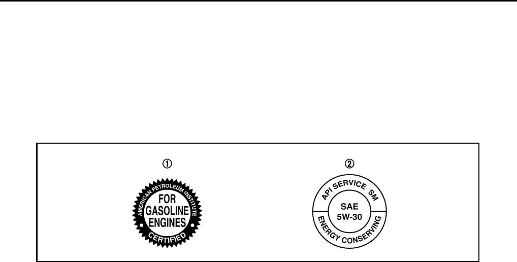
FOR NORTH AMERICA : Engine Oil Recommendation INFOID:0000000007466281
NISSAN recommends the use of an energy conserving oil in order to improve fuel economy.
Select only engine oils that meet the American Petroleum Institute (API) certification and International Lubri-
cant Standardization and Approval Committee (ILSAC) certification and SAE viscosity standard. These oils
have the API certification mark on the front of the container. Oils which do not have the specified quality label
should not be used as they could cause engine damage.
FOR NORTH AMERICA : Anti-Freeze Coolant Mixture Ratio INFOID:0000000007466282
The engine cooling system is filled at the factory with a pre-diluted mixture of 50% Genuine NISSAN Long Life
Antifreeze/Coolant (blue) and 50% water to provide year-round anti-freeze and coolant protection. The anti-
freeze solution contains rust and corrosion inhibitors. Additional engine cooling system additives are not nec-
essary.
WARNING:
• Never remove the radiator or coolant reservoir cap when the engine is hot. Wait until the engine and
radiator cool down. Serious burns could be caused by high pressure fluid escaping from the radia-
tor.
• The radiator is equipped with a pressure type radiator cap. To prevent engine damage, use only a
genuine NISSAN radiator cap.
CAUTION:
• When adding or replacing coolant, be sure to use only Genuine NISSAN Long Life Antifreeze/Cool-
ant (blue) or equivalent. Genuine NISSAN Long Life Antifreeze/Coolant (blue) is pre-diluted to pro-
vide antifreeze protection to -34°F (-37°C). If additional freeze protection is needed due to weather
where you operate your vehicle, add Genuine NISSAN Long Life Antifreeze/Coolant (blue) concen-
trate following the directions on the container. If an equivalent coolant other than Genuine NISSAN
Long Life Antifreeze/Coolant (blue) is used, follow the coolant manufactur's instructions to maintain
minimum antifreeze protection to -34°F (-37°C). The use of other types of coolant solutions other
than Genuine NISSAN Long Life Antifreeze/Coolant (blue) or equivalent may damage the engine
cooling system.
• Mixing any other type of coolant other than Genuine NISSAN Long Life Antifreeze/Coolant (blue),
including Genuine NISSAN Long Life Antifreeze/Coolant (green), or the use of non-distilled water will
reduce the life expectancy of the factory-fill coolant.
FOR MEXICO
1. API certification mark 2. API service symbol
SAIA1514E
Revision: 2013 February 2012 G Sedan
RECOMMENDED FLUIDS AND LUBRICANTS
MA-19
< PERIODIC MAINTENANCE >
C
D
E
F
G
H
I
J
K
L
M
B
MA
N
O
A
FOR MEXICO : Fluids and Lubricants INFOID:0000000007793836
*1: For additional information, see “SAE Viscosity Number”.
*2: Use Genuine NISSAN Engine Coolant or equivalent in its quality, in order to avoid possible aluminum corrosion within the engine
cooling system caused by the use of non-genuine engine coolant.
Note that any repairs for the incidents within the engine cooling system while using non-genuine engine coolant may not be
covered by the warranty even if such incidents occurred during the warranty period.
*3: Using automatic transmission fluid other than Genuine NISSAN Matic S ATF will cause deterioration in driveability and automatic
transmission durability, and may damage the automatic transmission, which is not covered by warranty.
*4: The fluid capacity is the reference value.
*5: See an INFINITI dealer for service for synthetic oil.
*6: DEXRON™ VI type ATF may also be used.
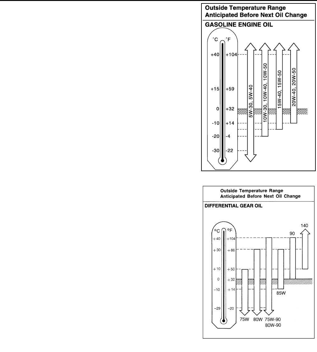
FOR MEXICO : SAE Viscosity Number INFOID:0000000007793837
GASOLINE ENGINE
Capacity (Approximate) Recommended Fluids/Lubricants
Liter Imp measure
Engine oil
Drain and re-
fill
With oil filter
change
VQ25HR 4.7 4-1/8 qt
Genuine NISSAN engine oil
API grade SL or SM*1
ILSAC grade GF-2, GF-3 or GF-4*1
Viscosity SAE 10W-30 except for VQ37 engine
Viscosity SAE 5W-30 for VQ37 engine
VQ37VHR 4.9 4-1/4 qt
Without oil filter
change
VQ25HR 4.4 3-7/8 qt
VQ37VHR 4.6 4 qt
Dry engine (engine overhaul) VQ25HR 5.4 4-6/8 qt
VQ37VHR 5.7 5 qt
Cooling system (with reservoir) VQ25HR 8.3 7-2/8 qt Genuine NISSAN Engine Coolant or equivalent in
its quality*2
VQ37VHR 8.5 7-1/2 qt
Reservoir tank 0.8 3/4 qt
Automatic transmission fluid 9.2*4 8-1/8 qt*4 Genuine NISSAN Matic S ATF*3
Differential gear oil 1.4 2-1/2 pt Genuine NISSAN Differential Oil Hypoid Super-S
GL-5 Synthetic 75W-90 or equivalent*5
Power steering fluid (PSF) 1.0 7/8 qt Genuine NISSAN PSF or equivalent*6
Brake fluid — — Genuine NISSAN Brake Fluid, or equivalent DOT
3 (US FMVSS No.116)
Multi-purpose grease — — NLGI No. 2 (Lithium soap base)
Revision: 2013 February 2012 G Sedan
MA-20
< PERIODIC MAINTENANCE >
RECOMMENDED FLUIDS AND LUBRICANTS
Except for VQ37 engine
• 10W-30 is preferable.
If 10W-30 is not available, select the viscosity, from the chart, that
is suitable for the outside temperature range.
For VQ37 engine
• 5W-30 is preferable.
If 5W-30 is not available, select the viscosity, from the chart, that is
suitable for the outside temperature range.
DIFFERENTIAL GEAR OIL
• 75W-90 for the differential gear is preferable.
JPPIA0003GB
JPPIA0001GB
Revision: 2013 February 2012 G Sedan

RECOMMENDED FLUIDS AND LUBRICANTS
MA-21
< PERIODIC MAINTENANCE >
C
D
E
F
G
H
I
J
K
L
M
B
MA
N
O
A
FOR MEXICO : Engine Coolant Mixture Ratio INFOID:0000000007793838
The engine cooling system is filled at the factory with a high-quality,
year-round and extended life engine coolant. The high quality engine
coolant contains the specific solutions effective for the anti-corrosion
and the anti-freeze function. Therefore, additional cooling system
additives are not necessary.
CAUTION:
• When adding or replacing coolant, be sure to use only Genu-
ine NISSAN Engine Coolant or equivalent in its quality with
the proper mixture ratio. See the examples shown right.
The use of other types of engine coolant may damage the
engine cooling system.
• When checking the engine coolant mixture ratio by the coolant
hydrometer, use the chart below to correct your hydrometer reading (specific gravity) according to coolant
temperature.
Mixed coolant specific gravity
Unit: specific gravity
WARNING:
Never remove the radiator cap when the engine is hot. Serious burns could be caused by high pres-
sure fluid escaping from the radiator. Wait until the engine and radiator cool down.
SMA089D
Engine coolant mixture
ratio
Coolant temperature °C (°F)
15 (59) 25 (77) 35 (95) 45 (113)
30% 1.046 - 1.050 1.042 - 1.046 1.038 - 1.042 1.033 - 1.038
50% 1.076 - 1.080 1.070 - 1.076 1.065 - 1.071 1.059 - 1.065
Revision: 2013 February 2012 G Sedan
MA-22
< PERIODIC MAINTENANCE >
ENGINE MAINTENANCE (VQ37VHR)
ENGINE MAINTENANCE (VQ37VHR)
DRIVE BELT
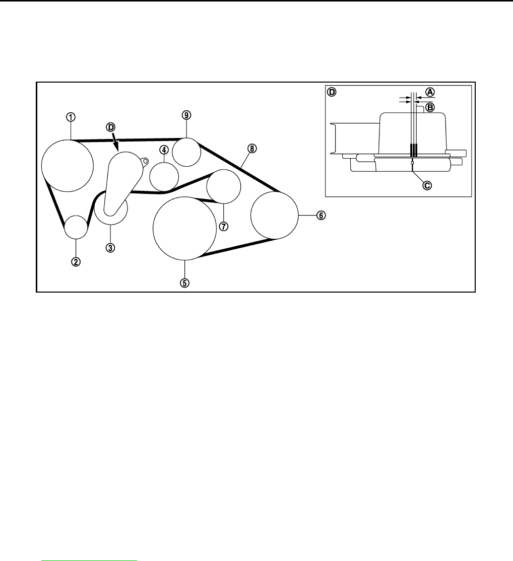
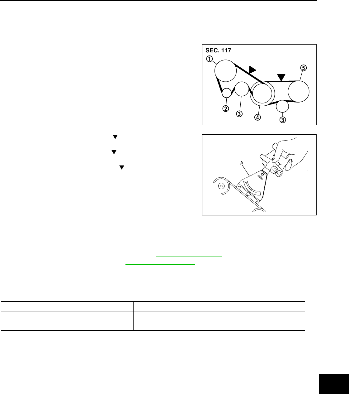
DRIVE BELT : Exploded View INFOID:0000000007466283
DRIVE BELT : Checking INFOID:0000000007466284
WARNING:
Be sure to perform the this step when engine is stopped.
• Check that the indicator (C) (notch on fixed side) of drive belt auto-tensioner is within the possible use range
(A).
NOTE:
• Check the drive belt auto-tensioner indication when the engine is cold.
• When new drive belt is installed, the indicator (notch on fixed side) should be within the range (B) in the fig-
ure.
• Visually check the entire drive belt for wear, damage or crack.
• If the indicator (notch on fixed side) is out of the possible use range or belt is damaged, replace drive belt.
DRIVE BELT : Tension Adjustment INFOID:0000000007797874
Refer to EM-300, "Drive Belt".
ENGINE COOLANT
ENGINE COOLANT : Draining INFOID:0000000007466286
WARNING:
• To avoid being scalded, never change engine coolant when the engine is hot.
• Wrap a thick cloth around radiator cap and carefully remove radiator cap. First, turn radiator cap a
quarter of a turn to release built-up pressure. Then turn radiator cap all the way.
JPBIA1060ZZ
1. Power steering oil pump 2. Alternator 3. Drive belt auto-tensioner
4. Idler pulley 5. Crankshaft pulley 6. A/C compressor
7. Idler pulley 8. Drive belt 9. Idler pulley
A. Possible use range B. Range when new drive belt is installed C. Indicator
D. View D
Revision: 2013 February 2012 G Sedan

ENGINE MAINTENANCE (VQ37VHR)
MA-23
< PERIODIC MAINTENANCE >
C
D
E
F
G
H
I
J
K
L
M
B
MA
N
O
A
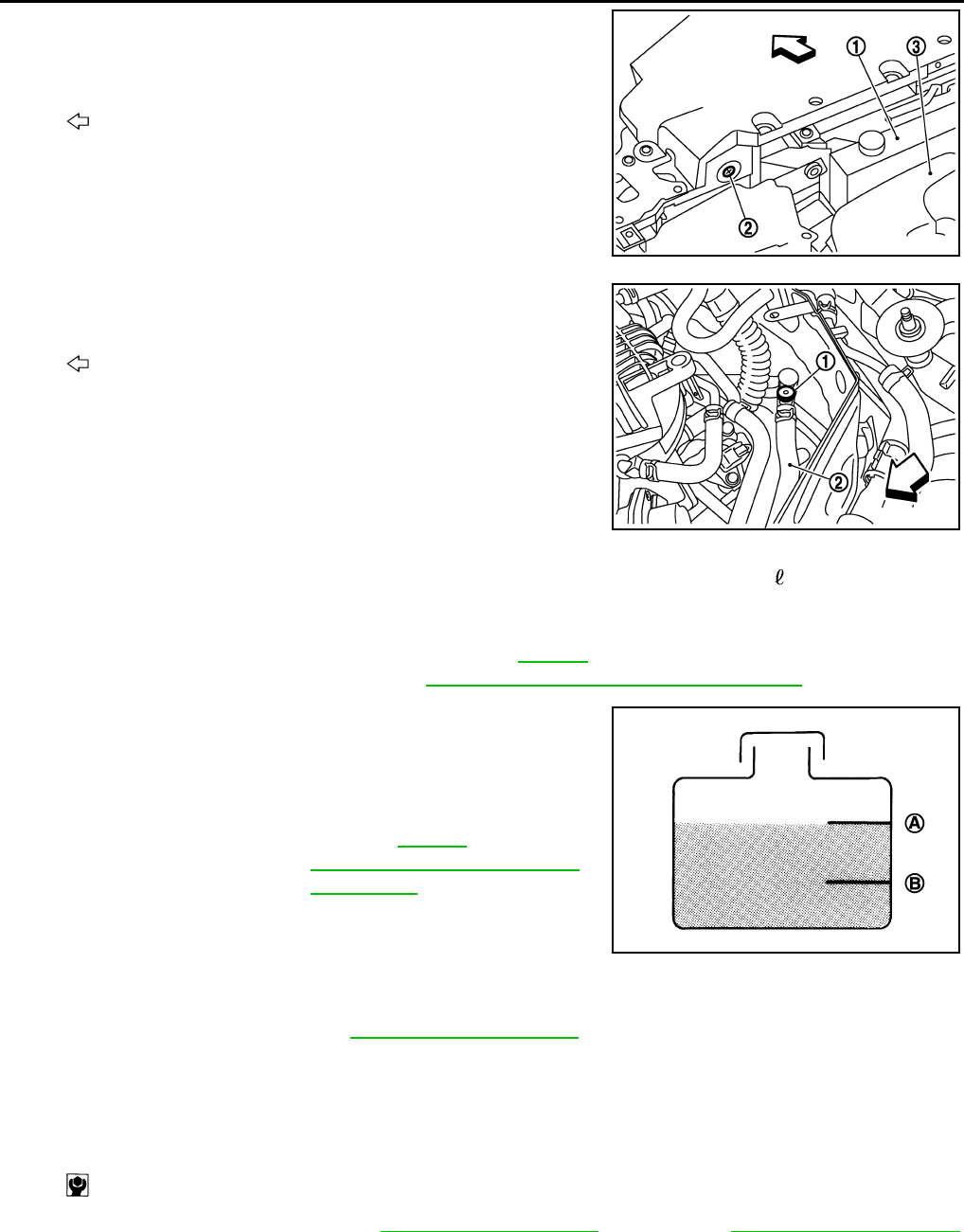
1. Connect drain hose.
NOTE:
Use a general-purpose hose with the dimmensions shown in the
figure.
2. Open radiator drain plug (2) at the bottom of radiator, and then
remove radiator cap.
When draining all of engine coolant in the system, open water drain plugs on cylinder block. Refer
to EM-93, "Setting" (VQ25HR) or EM-231, "Setting" (VQ37VHR).
3. Remove reservoir tank if necessary, and drain engine coolant and clean reservoir tank before installing.
4. Check drained engine coolant for contaminants such as rust, corrosion or discoloration.
If contaminated, flush the engine cooling system. Refer to MA-25, "ENGINE COOLANT : Flushing".
ENGINE COOLANT : Refilling INFOID:0000000007793968
CAUTION:
• Do not reuse O-rings.
• Do not put additive such as waterleak preventive, since it may cause cooling waterway clogging.
• When refilling use Genuine NISSAN Long Life Antifreeze/Coolant (blue) or equivalent in its quality
mixed with water (distilled or demineralized). Refer to MA-17, "FOR NORTH AMERICA : Fluids and
Lubricants" (FOR NORTH AMERICA) or MA-19, "FOR MEXICO : Fluids and Lubricants"(FOR MEX-
ICO).
1. Remove air cleaner case (LH). Refer to EM-28, "Exploded View" (VQ25HR) or EM-179, "Exploded View"
(VQ37VHR).
2. Install reservoir tank if removed, and radiator drain plug.
CAUTION:
Be sure to clean drain plug and install with new O-ring.
If water drain plugs on cylinder block are removed, close and tighten them. Refer to EM-93, "Set-
ting" (VQ25HR) or EM-231, "Setting" (VQ37VHR).
3. Check that each hose clamp has been firmly tightened.
A: φ 15 - 16 mm (0.59 - 0.63 in)
B : 145 mm (5.71 in)
JPBIA4770ZZ
1 : Engine under cover
A : Radiator drain plug hole
: Vehicle front
JPBIA0259ZZ
Tightening torque : Refer to CO-15, "Exploded View".
Revision: 2013 February 2012 G Sedan
MA-24
< PERIODIC MAINTENANCE >
ENGINE MAINTENANCE (VQ37VHR)
4. Remove air relief plug (2) on radiator left side.
5. Remove air relief plug (1) on heater hose.
6. Fill radiator to specified level.
•Pour engine coolant through engine coolant filler neck slowly of less than 2 (2-1/8 US qt, 1-3/4
lmp qt) a minute to allow air in system to escape.
7. Refill reservoir tank to “MAX” level line with engine coolant.
8. When engine coolant overflows air relief hole on radiator, install air relief plug with new O-ring.
9. Repeat step 6 and 7.
10. When engine coolant overflows air relief hole on heater hose, install air relief plug with new O-ring. Then
refill radiator with engine coolant.
11. Install air cleaner case (LH). Refer to EM-28, "Exploded View" (VQ25HR) or EM-179, "Exploded View"
(VQ37VHR).
12. Install radiator cap.
13. Warm up engine until opening thermostat. Standard for warming-up time is approximately 10 minutes at
3,000 rpm.
1 : Reservoir tank
3 : Engine cover
: Vehicle front
JPBIA0260ZZ
2 : Heater hose
: Vehicle front
JPBIA0104ZZ
Engine coolant capacity : Refer to CO-34,
"Periodical Maintenance Specification".
(With reservoir tank at “MAX” level)
A : MAX
B: MIN
Reservoir tank engine
coolant capacity :Refer to CO-34,
"Periodical Maintenance Sp
ecification"
(At “MAX” level)
JPBIA0102ZZ
Tightening torque : Refer to CO-15, "Exploded View".
: 1.2 N·m (0.12 kg-m, 11 in-lb)
Revision: 2013 February 2012 G Sedan

ENGINE MAINTENANCE (VQ37VHR)
MA-25
< PERIODIC MAINTENANCE >
C
D
E
F
G
H
I
J
K
L
M
B
MA
N
O
A
• Check thermostat opening condition by touching radiator hose (lower) to see a flow of warm water.
CAUTION:
Watch water temperature gauge so as not to overheat engine.
14. Stop the engine and cool down to less than approximately 50°C (122°F).
• Cool down using fan to reduce the time.
• If necessary, refill radiator up to filler neck with engine coolant.
15. Refill reservoir tank to “MAX” level line with engine coolant, if necessary.
16. Repeat steps 12 through 15 two or more times with radiator cap installed until engine coolant level no
longer drops.
17. Check cooling system for leakage with engine running.
18. Warm up the engine, and check for sound of engine coolant flow while running engine from idle up to
3,000 rpm with heater temperature controller set at several position between “COOL” and “WARM”.
• Sound may be noticeable at heater unit.
19. Repeat step 18 three times.
20. If sound is heard, bleed air from cooling system by repeating step 6, and steps from 12 to 19 until engine
coolant level no longer drops.
21. Check that the reservoir tank cap is tightened.
ENGINE COOLANT : Flushing INFOID:0000000007466288
1. Install reservoir tank if removed, and radiator drain plug.
CAUTION:
Be sure to clean drain plug and install with new O-ring.
If water drain plugs on cylinder block are removed, close and tighten them. Refer to EM-231, "Set-
ting".
2. Remove air relief plug (1) on heater hose (2).
3. Remove air relief plug (2) on radiator.
4. Fill radiator with water until water spills from the air relief holes, then close air relief plugs. Fill radiator and
reservoir tank with water and reinstall radiator cap.
5. Run the engine and warm it up to normal operating temperature.
Tightening torque : Refer to CO-15, "Exploded View".
: Vehicle front
JPBIA0104ZZ
1 : Reservoir tank
3 : Engine cover
: Vehicle front
JPBIA0260ZZ
Tightening torque : Refer to CO-15, "Exploded View".
Revision: 2013 February 2012 G Sedan

MA-26
< PERIODIC MAINTENANCE >
ENGINE MAINTENANCE (VQ37VHR)
6. Rev the engine two or three times under no-load.
7. Stop the engine and wait until it cools down.
8. Drain water from the system. Refer to MA-22, "ENGINE COOLANT : Draining".
9. Repeat steps 1 through 8 until clear water begins to drain from radiator.
10. Check that the reservoir tank cap is tightened.
FUEL LINES
FUEL LINES : Inspection INFOID:0000000007466289
Inspect fuel lines, fuel filler cap and fuel tank for improper attach-
ment, leakage, cracks, damage, loose connections, chafing or dete-
rioration.
If necessary, repair or replace damaged parts.
AIR CLEANER FILTER
AIR CLEANER FILTER : Removal and Installation INFOID:0000000007466290
REMOVAL
1. Unhook clips (A).
2. Remove holder (3) from air cleaner case (2), and then remove
air cleaner filter (1) from holder.
INSTALLATION
Note the following, and install in the reverse order of removal.
• Install the air cleaner filter by aligning the seal with the notch of air cleaner case.
ENGINE OIL
ENGINE OIL : Draining INFOID:0000000007466291
WARNING:
A : Engine
B : Fuel line
C: Fuel tank
JPBIA0129ZZ
1: Holder
2 : Air cleaner case
JPBIA1597ZZ
JPBIA1598ZZ
Revision: 2013 February 2012 G Sedan
ENGINE MAINTENANCE (VQ37VHR)
MA-27
< PERIODIC MAINTENANCE >
C
D
E
F
G
H
I
J
K
L
M
B
MA
N
O
A
• Be careful not to get burn yourself, as engine oil may be hot.
• Prolonged and repeated contact with used engine oil may cause skin cancer. Try to avoid direct skin
contact with used engine oil. If skin contact is made, wash thoroughly with soap or hand cleaner as
soon as possible.
1. Warm up the engine, and check for engine oil leakage from engine components. Refer to LU-9, "Inspec-
tion".
2. Stop the engine and wait for 10 minutes.
3. Loosen oil filler cap.
4. Remove undercover with power tool.
5. Remove drain plug and then drain engine oil.
ENGINE OIL : Refilling INFOID:0000000007466292
1. Install drain plug with new washer. Refer to EM-195, "Exploded View (2WD)".
CAUTION:
Be sure to clean drain plug and install with new washer.
2. Refill with new engine oil.
Engine oil specification and viscosity: Refer to MA-17, "FOR NORTH AMERICA : Fluids and Lubri-
cants".
CAUTION:
• When filling engine oil, do not pull out oil level gauge.
• The refill capacity depends on the engine oil temperature and drain time. Use these specifica-
tions for reference only.
• Always use oil level gauge to determine the proper amount of engine oil in engine.
3. Warm up the engine and check area around drain plug and oil filter for engine oil leakage.
4. Stop the engine and wait for 10 minutes.
5. Check the engine oil level. Refer to LU-9, "Inspection".
OIL FILTER
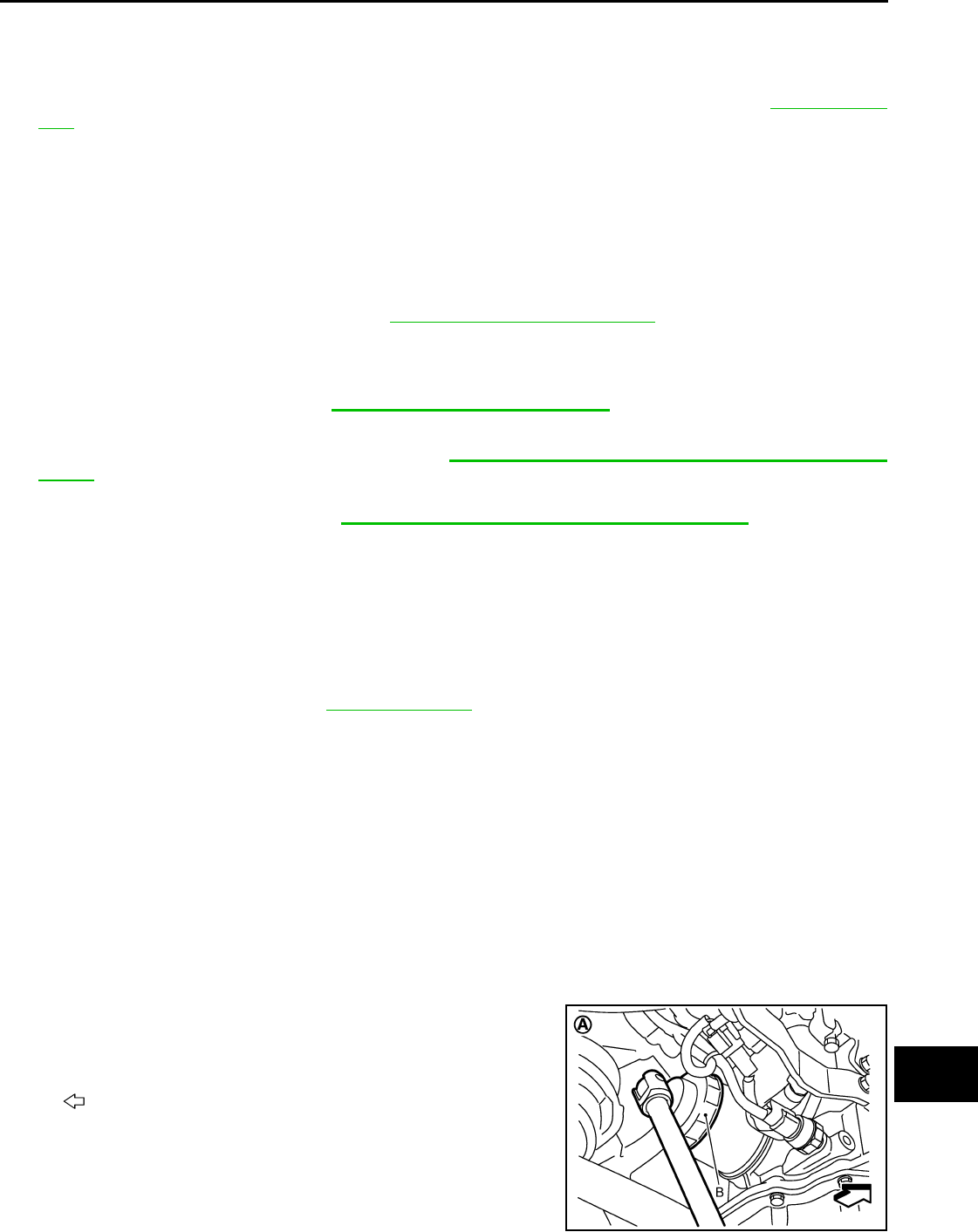
OIL FILTER : Removal and Installation INFOID:0000000007797876
REMOVAL
CAUTION:
• Oil filter is provided with relief valve. Use genuine NISSAN oil filter or equivalent.
• Never get burned when engine and engine oil may be hot.
• When removing, prepare a shop cloth to absorb any engine oil leakage or spillage.
• Never allow engine oil to adhere to drive belt.
• Completely wipe off any engine oil that adheres to engine and vehicle.
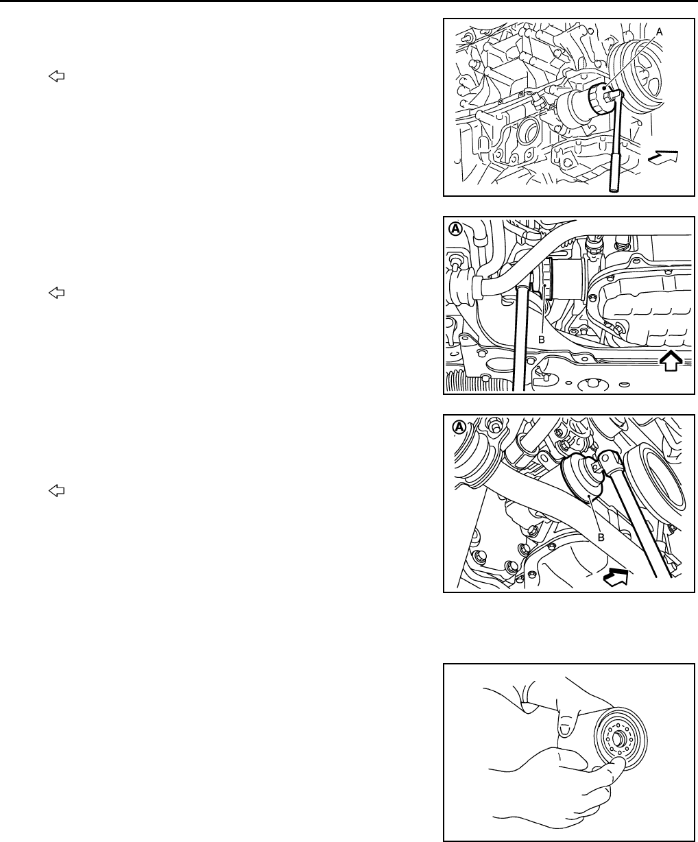
1. Remove engine undercover with power tool.
2. Using oil filter wrench [SST: KV10115801 (J-38956)], remove oil filter.
• VQ25HR 2WD models
Tightening torque : Refer to EM-195, "Exploded View (2WD)".
Engine oil capacity : Refer to LU-23, "Periodical Maintenance Specification".
A : Vehicle under view
B : Oil filter wrench
: Engine front
JPBIA1768ZZ
Revision: 2013 February 2012 G Sedan
MA-28
< PERIODIC MAINTENANCE >
ENGINE MAINTENANCE (VQ37VHR)
• VQ25HR AWD models
• VQ37VHR 2WD models
• VQ37VHR AWD models
INSTALLATION
1. Remove foreign materials adhering to oil filter installation surface.
2. Apply engine oil to the oil seal contact surface of new oil filter.
A : Oil filter wrench
: Engine front
JPBIA4831ZZ
A : Vehicle under view
B : Oil filter wrench
: Engine front
JPBIA0252GB
A : Vehicle under view
B : Oil filter wrench
: Engine front
JPBIA1828ZZ
SMA010
Revision: 2013 February 2012 G Sedan
ENGINE MAINTENANCE (VQ37VHR)
MA-29
< PERIODIC MAINTENANCE >
C
D
E
F
G
H
I
J
K
L
M
B
MA
N
O
A
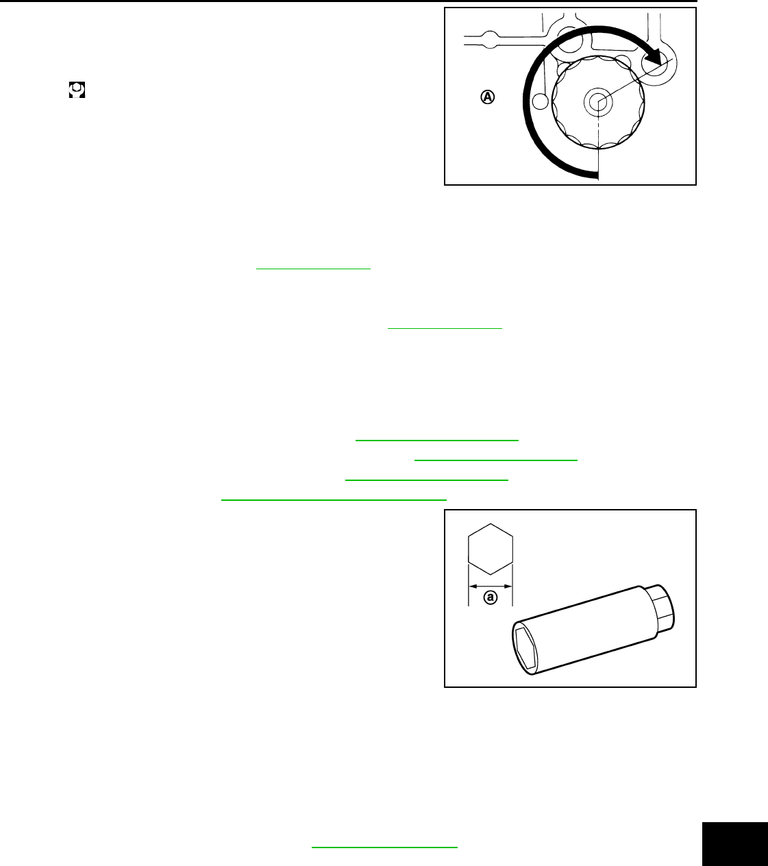
3. Screw oil filter manually until it touches the installation surface,
then tighten it by 2/3 turn (A). Or tighten to the specification.
OIL FILTER : Inspection INFOID:0000000007466294
INSPECTION AFTER INSTALLATION
1. Check the engine oil level. Refer to LU-9, "Inspection".
2. Start the engine, and check there is no leak of engine oil.
3. Stop the engine and wait for 10 minutes.
4. Check the engine oil level, and adjust the level. Refer to LU-9, "Inspection".
SPARK PLUG
SPARK PLUG : Removal and Installation INFOID:0000000007797875
REMOVAL
1. Remove engine cover, using a power tool. Refer to EM-177, "Exploded View".
2. Remove air cleaner case and air duct (RH and LH). Refer to EM-179, "Exploded View".
3. Remove electric throttle control actuator. Refer to EM-181, "Exploded View".
4. Remove ignition coil. Refer to EM-199, "Removal and Installation".
5. Remove spark plug with a spark plug wrench (commercial ser-
vice tool).
INSTALLATION
Installation is the reverse order of removal.
SPARK PLUG : Inspection INFOID:0000000007466296
INSPECTION AFTER REMOVAL
Use the standard type spark plug for normal condition.
CAUTION:
Oil filter:
: 17.7 N·m (1.8 kg-m, 13 ft-lb)
JPBIA0077ZZ
a : 14 mm (0.55 in)
JPBIA0030ZZ
Spark plug (Standard type) : Refer to EM-300, "Spark Plug".
Revision: 2013 February 2012 G Sedan
MA-30
< PERIODIC MAINTENANCE >
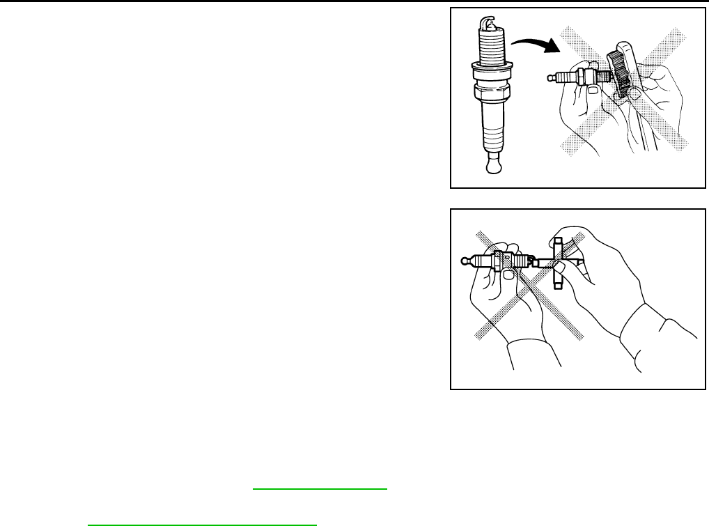
ENGINE MAINTENANCE (VQ37VHR)
• Never drop or shock spark plug.
• Never use a wire brush for cleaning.
• If plug tip is covered with carbon, use spark plug cleaner to
clean.
• Check and adjustment of plug gap is not required between
change intervals.
EVAP VAPOR LINES
EVAP VAPOR LINES : Inspection INFOID:0000000007466297
1. Visually inspect EVAP vapor lines for improper attachment and for cracks, damage, loose connections,
chafing and deterioration. Refer to EC-623, "Inspection".
2. Inspect fuel tank filler cap vacuum relief valve for clogging, sticking, etc.
Refer to EC-373, "Component Inspection".
Cleaner air pressure
: Less than 588 kPa (6 kg/cm2, 85 psi)
Cleaning time
: Less than 20 seconds
SMA773C
JPBIA0031ZZ
Revision: 2013 February 2012 G Sedan
ENGINE MAINTENANCE (VQ25HR)
MA-31
< PERIODIC MAINTENANCE >
C
D
E
F
G
H
I
J
K
L
M
B
MA
N
O
A
ENGINE MAINTENANCE (VQ25HR)
DRIVE BELT
DRIVE BELT : Inspection INFOID:0000000007466298
• Check the belt with the engine cold or after a lapse of 30 minutes
or more after the engine is stopped.
• Measure belt tension at the position as shown in the figure with
the tension gauge [SST: KV99105600 ( — )] (A). If it is difficult to
measure the tension at the position , then a nearby position can
be measured.
• Apply the force of 98.1 N (10kg) at the position shown in the fig-
ure also when measuring by deflection amount.
CAUTION:
• To check belt tension right after belt installation, adjust belt
tension to the reference value and rotate the crankshaft
twice or more to prevent variations in the tension between
pulleys. Measure belt tension again and adjust to the refer-
ence value.
• Tighten Idler pulley lock nut by hand and measure tension in backlash-free condition.
DRIVE BELT : Adjustment INFOID:0000000007466299
CAUTION:
• After replacing belt with a new one, adjust it to the value of "NEW" since new ones do not sufficiently
fit in with pulley grooves.
• If the belt in use exceeds the value of "Limit of Retightening," adjust the belt to the value of "For
Adjustment."
• To check belt tension right after belt installation, adjust belt tension to the reference value and rotate
the crankshaft twice or more to prevent variations in the tension between pulleys. Measure belt ten-
sion again and adjust to the reference value.
• After installing belt, check that it is completely fit into the pulley groove.
• Never allow oil and coolant to adhere to the belt.
• Never twist or bend the belt.
Alternator ·power steering oil pump belt
1. Remove engine under cover with power tool.
1 : Power steering oil pump
2: Alternator
3 : Idler pulley
4 : Crankshaft pulley
5: A/C compressor
JPBIA0421ZZ
JPBIA0422ZZ
Auxiliary machine belt tension : Refer to MA-57, "DRIVE BELT
(VQ25HR) : Drive Belt"
Deflection amount of auxiliary
machine belt
Portion Belt tightening method for adjustment
Alternator·Power steering oil pump belt Adjusting bolt of idler pulley
A/C compressor belt Adjusting bolt of idler pulley
Revision: 2013 February 2012 G Sedan
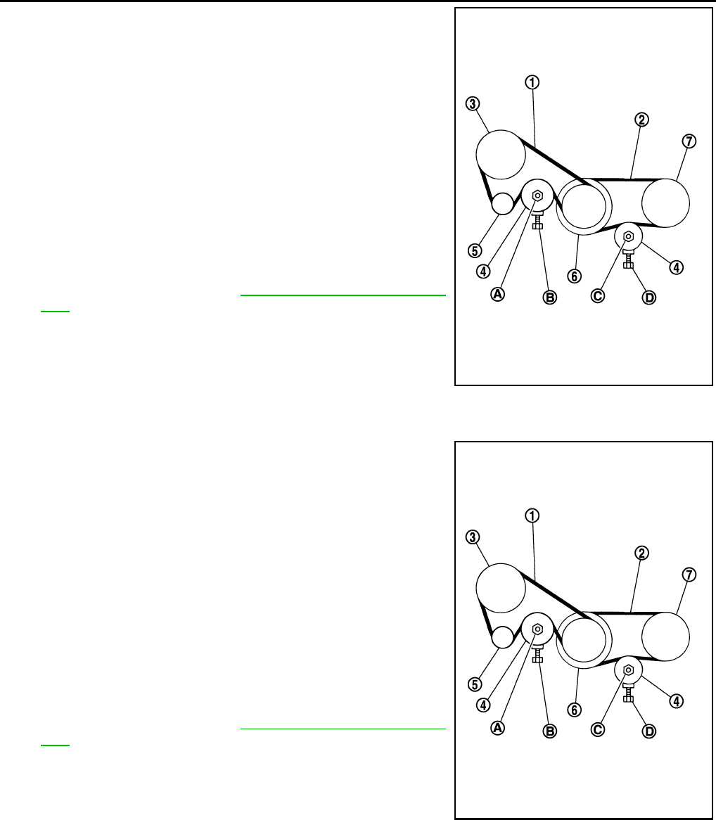
MA-32
< PERIODIC MAINTENANCE >
ENGINE MAINTENANCE (VQ25HR)
2. Loosening idler pulley rock nut (A).
3. Adjust tension by turning adjusting bolt (B).
CAUTION:
Adjusting bolts are applied with grease. Never allow the
grease to adhere to the belt.
• For adjustment value, refer to MA-31, "DRIVE BELT : Inspec-
tion".
4. Tightening idler pulley rock nut (A).
A/C compressor belt
1. Remove engine under cover with power tool.
2. Loosening idler pulley rock nut (C).
3. Adjust tension by turning adjusting bolt (D).
CAUTION:
Adjusting bolts are applied with grease. Never allow the
grease to adhere to the belt.
• For adjustment value, refer to MA-31, "DRIVE BELT : Inspec-
tion".
4. Tightening idler pulley rock nut (C).
ENGINE COOLANT
ENGINE COOLANT : Draining INFOID:0000000007466300
WARNING:
• To avoid being scalded, never change engine coolant when the engine is hot.
• Wrap a thick cloth around radiator cap and carefully remove radiator cap. First, turn radiator cap a
quarter of a turn to release built-up pressure. Then turn radiator cap all the way.
1 : Alternator ·power steering oil pump belt
2 : A/C compressor belt
3 : Power steering oil pump
4 : Idler pulley
5 : Alternator
6 : Crankshaft pulley
7 : A/C compressor
C : Idler pulley rock nut
D : Adjustment bolt
Tightening torque 34.8 N·m (3.5 kg-m)
JPBIA0423ZZ
1 : Alternator ·power steering oil pump belt
2 : A/C compressor belt
3 : Power steering oil pump
4 : Idler pulley
5 : Alternator
6 : Crankshaft pulley
7 : A/C compressor
A : Idler pulley rock nut
B : Adjustment bolt
Tightening torque 34.8 N·m (3.5 kg-m)
JPBIA0423ZZ
Revision: 2013 February 2012 G Sedan
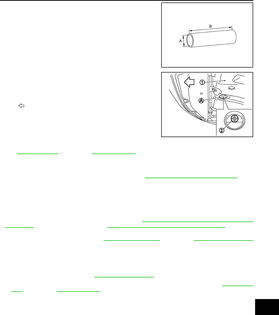
ENGINE MAINTENANCE (VQ25HR)
MA-33
< PERIODIC MAINTENANCE >
C
D
E
F
G
H
I
J
K
L
M
B
MA
N
O
A
1. Connect drain hose.
NOTE:
Use a general-purpose hose with the dimmensions shown in the
figure.
2. Open radiator drain plug (2) at the bottom of radiator, and then
remove radiator cap.
When draining all of engine coolant in the system, open water drain plugs on cylinder block. Refer
to EM-93, "Setting" (VQ25HR) or EM-231, "Setting" (VQ37VHR).
3. Remove reservoir tank if necessary, and drain engine coolant and clean reservoir tank before installing.
4. Check drained engine coolant for contaminants such as rust, corrosion or discoloration.
If contaminated, flush the engine cooling system. Refer to MA-25, "ENGINE COOLANT : Flushing".
ENGINE COOLANT : Refilling INFOID:0000000007793967
CAUTION:
• Do not reuse O-rings.
• Do not put additive such as waterleak preventive, since it may cause cooling waterway clogging.
• When refilling use Genuine NISSAN Long Life Antifreeze/Coolant (blue) or equivalent in its quality
mixed with water (distilled or demineralized). Refer to MA-17, "FOR NORTH AMERICA : Fluids and
Lubricants" (FOR NORTH AMERICA) or MA-19, "FOR MEXICO : Fluids and Lubricants"(FOR MEX-
ICO).
1. Remove air cleaner case (LH). Refer to EM-28, "Exploded View" (VQ25HR) or EM-179, "Exploded View"
(VQ37VHR).
2. Install reservoir tank if removed, and radiator drain plug.
CAUTION:
Be sure to clean drain plug and install with new O-ring.
If water drain plugs on cylinder block are removed, close and tighten them. Refer to EM-93, "Set-
ting" (VQ25HR) or EM-231, "Setting" (VQ37VHR).
3. Check that each hose clamp has been firmly tightened.
A: φ 15 - 16 mm (0.59 - 0.63 in)
B : 145 mm (5.71 in)
JPBIA4770ZZ
1 : Engine under cover
A : Radiator drain plug hole
: Vehicle front
JPBIA0259ZZ
Tightening torque : Refer to CO-15, "Exploded View".
Revision: 2013 February 2012 G Sedan

MA-34
< PERIODIC MAINTENANCE >
ENGINE MAINTENANCE (VQ25HR)
4. Remove air relief plug (2) on radiator left side.
5. Remove air relief plug (1) on heater hose.
6. Fill radiator to specified level.
•Pour engine coolant through engine coolant filler neck slowly of less than 2 (2-1/8 US qt, 1-3/4
lmp qt) a minute to allow air in system to escape.
7. Refill reservoir tank to “MAX” level line with engine coolant.
8. When engine coolant overflows air relief hole on radiator, install air relief plug with new O-ring.
9. Repeat step 6 and 7.
10. When engine coolant overflows air relief hole on heater hose, install air relief plug with new O-ring. Then
refill radiator with engine coolant.
11. Install air cleaner case (LH). Refer to EM-28, "Exploded View" (VQ25HR) or EM-179, "Exploded View"
(VQ37VHR).
12. Install radiator cap.
13. Warm up engine until opening thermostat. Standard for warming-up time is approximately 10 minutes at
3,000 rpm.
1 : Reservoir tank
3 : Engine cover
: Vehicle front
JPBIA0260ZZ
2 : Heater hose
: Vehicle front
JPBIA0104ZZ
Engine coolant capacity : Refer to CO-34,
"Periodical Maintenance Specification".
(With reservoir tank at “MAX” level)
A : MAX
B: MIN
Reservoir tank engine
coolant capacity :Refer to CO-34,
"Periodical Maintenance Sp
ecification"
(At “MAX” level)
JPBIA0102ZZ
Tightening torque : Refer to CO-15, "Exploded View".
: 1.2 N·m (0.12 kg-m, 11 in-lb)
Revision: 2013 February 2012 G Sedan
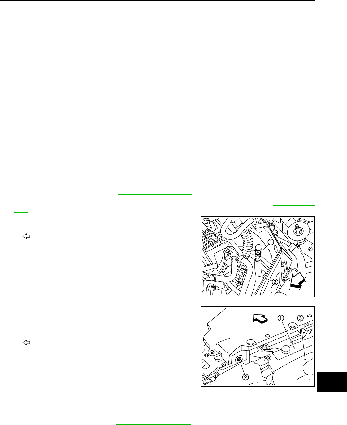
ENGINE MAINTENANCE (VQ25HR)
MA-35
< PERIODIC MAINTENANCE >
C
D
E
F
G
H
I
J
K
L
M
B
MA
N
O
A
• Check thermostat opening condition by touching radiator hose (lower) to see a flow of warm water.
CAUTION:
Watch water temperature gauge so as not to overheat engine.
14. Stop the engine and cool down to less than approximately 50°C (122°F).
• Cool down using fan to reduce the time.
• If necessary, refill radiator up to filler neck with engine coolant.
15. Refill reservoir tank to “MAX” level line with engine coolant, if necessary.
16. Repeat steps 12 through 15 two or more times with radiator cap installed until engine coolant level no
longer drops.
17. Check cooling system for leakage with engine running.
18. Warm up the engine, and check for sound of engine coolant flow while running engine from idle up to
3,000 rpm with heater temperature controller set at several position between “COOL” and “WARM”.
• Sound may be noticeable at heater unit.
19. Repeat step 18 three times.
20. If sound is heard, bleed air from cooling system by repeating step 6, and steps from 12 to 19 until engine
coolant level no longer drops.
21. Check that the reservoir tank cap is tightened.
ENGINE COOLANT : Flushing INFOID:0000000007466302
1. Install reservoir tank if removed, and radiator drain plug.
CAUTION:
Be sure to clean drain plug and install with new O-ring.
If water drain plugs on cylinder block are removed, close and tighten them. Refer to EM-231, "Set-
ting".
2. Remove air relief plug (1) on heater hose (2).
3. Remove air relief plug (2) on radiator.
4. Fill radiator with water until water spills from the air relief holes, then close air relief plugs. Fill radiator and
reservoir tank with water and reinstall radiator cap.
5. Run the engine and warm it up to normal operating temperature.
Tightening torque : Refer to CO-15, "Exploded View".
: Vehicle front
JPBIA0104ZZ
1 : Reservoir tank
3 : Engine cover
: Vehicle front
JPBIA0260ZZ
Tightening torque : Refer to CO-15, "Exploded View".
Revision: 2013 February 2012 G Sedan
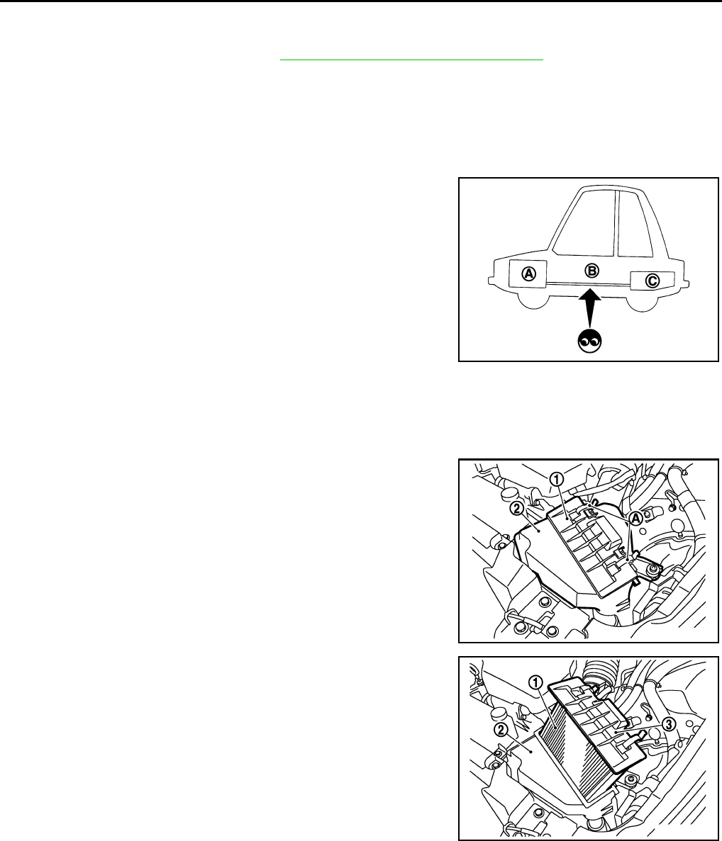
MA-36
< PERIODIC MAINTENANCE >
ENGINE MAINTENANCE (VQ25HR)
6. Rev the engine two or three times under no-load.
7. Stop the engine and wait until it cools down.
8. Drain water from the system. Refer to MA-22, "ENGINE COOLANT : Draining".
9. Repeat steps 1 through 8 until clear water begins to drain from radiator.
10. Check that the reservoir tank cap is tightened.
FUEL LINES
FUEL LINES : Inspection INFOID:0000000007466303
Inspect fuel lines, fuel filler cap and fuel tank for improper attach-
ment, leakage, cracks, damage, loose connections, chafing or dete-
rioration.
If necessary, repair or replace damaged parts.
AIR CLEANER FILTER
AIR CLEANER FILTER : Removal and Installation INFOID:0000000007466304
REMOVAL
1. Unhook clips (A).
2. Remove air cleaner filter (1) from air cleaner case (2).
INSTALLATION
Note the following, and install in the reverse order of removal.
• Install the air cleaner filter by aligning the seal with the notch of air cleaner case.
ENGINE OIL
ENGINE OIL : Draining INFOID:0000000007466305
WARNING:
A : Engine
B : Fuel line
C: Fuel tank
JPBIA0129ZZ
1: Holder
2 : Air cleaner case
JPBIA1597ZZ
3: Holder
JPBIA1598ZZ
Revision: 2013 February 2012 G Sedan

ENGINE MAINTENANCE (VQ25HR)
MA-37
< PERIODIC MAINTENANCE >
C
D
E
F
G
H
I
J
K
L
M
B
MA
N
O
A
• Be careful not to get burn yourself, as engine oil may be hot.
• Prolonged and repeated contact with used engine oil may cause skin cancer. Try to avoid direct skin
contact with used engine oil. If skin contact is made, wash thoroughly with soap or hand cleaner as
soon as possible.
1. Warm up the engine, and check for engine oil leakage from engine components. Refer to LU-9, "Inspec-
tion".
2. Stop the engine and wait for 10 minutes.
3. Loosen oil filler cap.
4. Remove undercover with power tool.
5. Remove drain plug and then drain engine oil.
ENGINE OIL : Refilling INFOID:0000000007466306
1. Install drain plug with new washer. Refer to EM-195, "Exploded View (2WD)".
CAUTION:
Be sure to clean drain plug and install with new washer.
2. Refill with new engine oil.
Engine oil specification and viscosity: Refer to MA-17, "FOR NORTH AMERICA : Fluids and Lubri-
cants".
CAUTION:
• When filling engine oil, do not pull out oil level gauge.
• The refill capacity depends on the engine oil temperature and drain time. Use these specifica-
tions for reference only.
• Always use oil level gauge to determine the proper amount of engine oil in engine.
3. Warm up the engine and check area around drain plug and oil filter for engine oil leakage.
4. Stop the engine and wait for 10 minutes.
5. Check the engine oil level. Refer to LU-9, "Inspection".
OIL FILTER
OIL FILTER : Removal and Installation INFOID:0000000007797879
REMOVAL
CAUTION:
• Oil filter is provided with relief valve. Use genuine NISSAN oil filter or equivalent.
• Never get burned when engine and engine oil may be hot.
• When removing, prepare a shop cloth to absorb any engine oil leakage or spillage.
• Never allow engine oil to adhere to drive belt.
• Completely wipe off any engine oil that adheres to engine and vehicle.
1. Remove engine undercover with power tool.
2. Using oil filter wrench [SST: KV10115801 (J-38956)], remove oil filter.
• VQ25HR 2WD models
Tightening torque : Refer to EM-195, "Exploded View (2WD)".
Engine oil capacity : Refer to LU-23, "Periodical Maintenance Specification".
A : Vehicle under view
B : Oil filter wrench
: Engine front
JPBIA1768ZZ
Revision: 2013 February 2012 G Sedan

MA-38
< PERIODIC MAINTENANCE >
ENGINE MAINTENANCE (VQ25HR)
• VQ25HR AWD models
• VQ37VHR 2WD models
• VQ37VHR AWD models
INSTALLATION
1. Remove foreign materials adhering to oil filter installation surface.
2. Apply engine oil to the oil seal contact surface of new oil filter.
A : Oil filter wrench
: Engine front
JPBIA4831ZZ
A : Vehicle under view
B : Oil filter wrench
: Engine front
JPBIA0252GB
A : Vehicle under view
B : Oil filter wrench
: Engine front
JPBIA1828ZZ
SMA010
Revision: 2013 February 2012 G Sedan
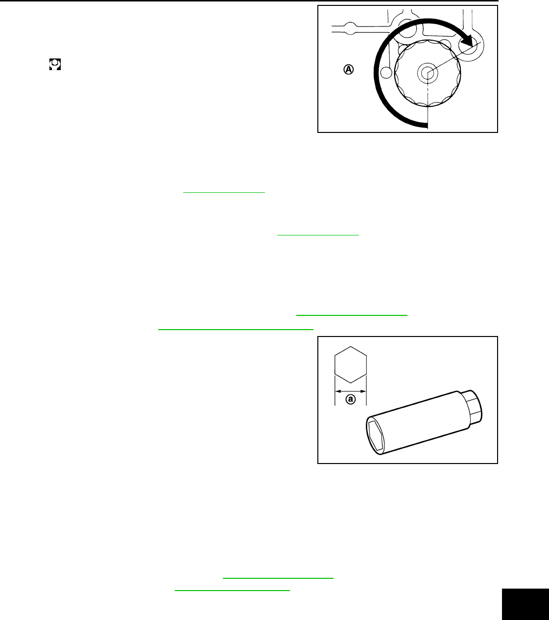
ENGINE MAINTENANCE (VQ25HR)
MA-39
< PERIODIC MAINTENANCE >
C
D
E
F
G
H
I
J
K
L
M
B
MA
N
O
A
3. Screw oil filter manually until it touches the installation surface,
then tighten it by 2/3 turn (A). Or tighten to the specification.
OIL FILTER : Inspection INFOID:0000000007466308
INSPECTION AFTER INSTALLATION
1. Check the engine oil level. Refer to LU-9, "Inspection".
2. Start the engine, and check there is no leak of engine oil.
3. Stop the engine and wait for 10 minutes.
4. Check the engine oil level, and adjust the level. Refer to LU-9, "Inspection".
SPARK PLUG
SPARK PLUG : Removal and Installation INFOID:0000000007466309
REMOVAL
1. Remove air cleaner case and air duct (RH and LH). Refer to EM-28, "Exploded View".
2. Remove ignition coil. Refer to EM-47, "Removal and Installation".
3. Remove spark plug with a spark plug wrench (commercial ser-
vice tool).
INSTALLATION
Installation is the reverse order of removal.
SPARK PLUG : Inspection INFOID:0000000007466310
INSPECTION AFTER REMOVAL
Use the standard type spark plug for normal condition.
CAUTION:
Oil filter:
: 17.7 N·m (1.8 kg-m, 13 ft-lb)
JPBIA0077ZZ
a : 14 mm (0.55 in)
JPBIA0030ZZ
Spark plug (Standard type) : Refer to MA-58, "SPARK PLUG
(VQ25HR) : Spark Plug".
Revision: 2013 February 2012 G Sedan
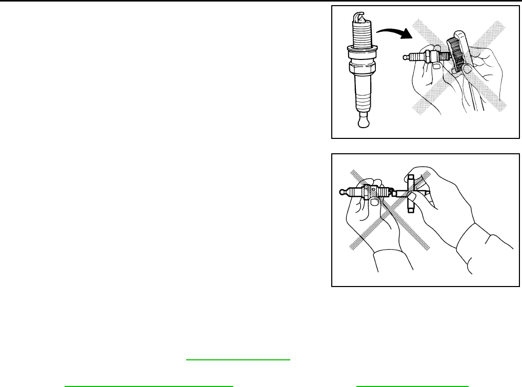
MA-40
< PERIODIC MAINTENANCE >
ENGINE MAINTENANCE (VQ25HR)
• Never drop or shock spark plug.
• Never use a wire brush for cleaning.
• If plug tip is covered with carbon, use spark plug cleaner to
clean.
• Check and adjustment of plug gap is not required between
change intervals.
EVAP VAPOR LINES
EVAP VAPOR LINES : Inspection INFOID:0000000007466311
1. Visually inspect EVAP vapor lines for improper attachment and for cracks, damage, loose connections,
chafing and deterioration. Refer to EC-1166, "Inspection" (For USA and Canada).
2. Inspect fuel tank filler cap vacuum relief valve for clogging, sticking, etc.
Refer to EC-373, "Component Inspection" (For USA and Canada), EC-1587, "Inspection" (For Mex-
ico).
Cleaner air pressure
: Less than 588 kPa (6 kg/cm2, 85 psi)
Cleaning time
: Less than 20 seconds
SMA773C
JPBIA0031ZZ
Revision: 2013 February 2012 G Sedan
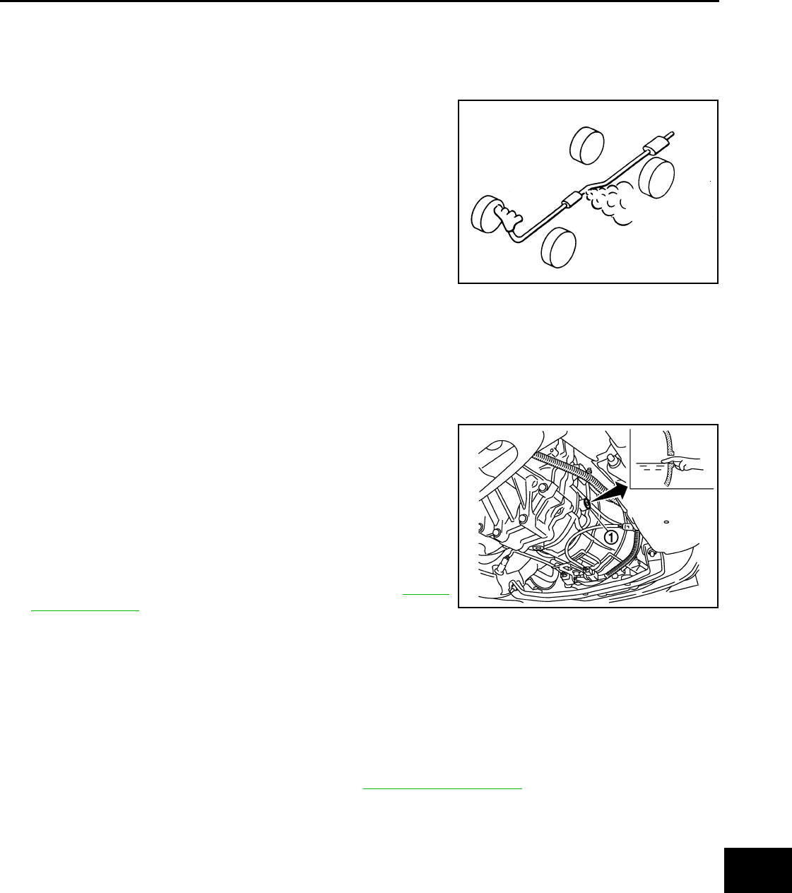
CHASSIS MAINTENANCE
MA-41
< PERIODIC MAINTENANCE >
C
D
E
F
G
H
I
J
K
L
M
B
MA
N
O
A
CHASSIS MAINTENANCE
EXHAUST SYSTEM
EXHAUST SYSTEM : Inspection INFOID:0000000007466312
Check exhaust pipes, muffler and mounting for improper attachment,
leaks, cracks, damage or deterioration.
• If anything is found, repair or replace damaged parts.
GEAR OIL
GEAR OIL : Inspection INFOID:0000000007466313
OIL LEAKAGE
Make sure that gear oil is not leaking from transmission or around it.
OIL LEVEL
1. Remove filler plug (1) and gasket from transmission case.
2. Check the oil level from filler plug mounting hole as shown in the
figure.
CAUTION:
Never start engine while checking oil level.
3. Set a gasket on filler plug and then install it to transmission
case.
CAUTION:
Never reuse gasket.
4. Tighten filler plug to the specified torque. Refer to TM-32,
"Exploded View".
GEAR OIL : Draining INFOID:0000000007466314
1. Start the engine and let it run to warm up transmission.
2. Stop the engine.
3. Remove drain plug and gasket from transmission case and then drain gear oil.
4. Set a gasket on drain plug and install it to transmission case.
CAUTION:
Never reuse gasket.
5. Tighten drain plug to the specified torque. Refer to TM-32, "Exploded View".
SMA211A
JPDIC0590ZZ
Revision: 2013 February 2012 G Sedan
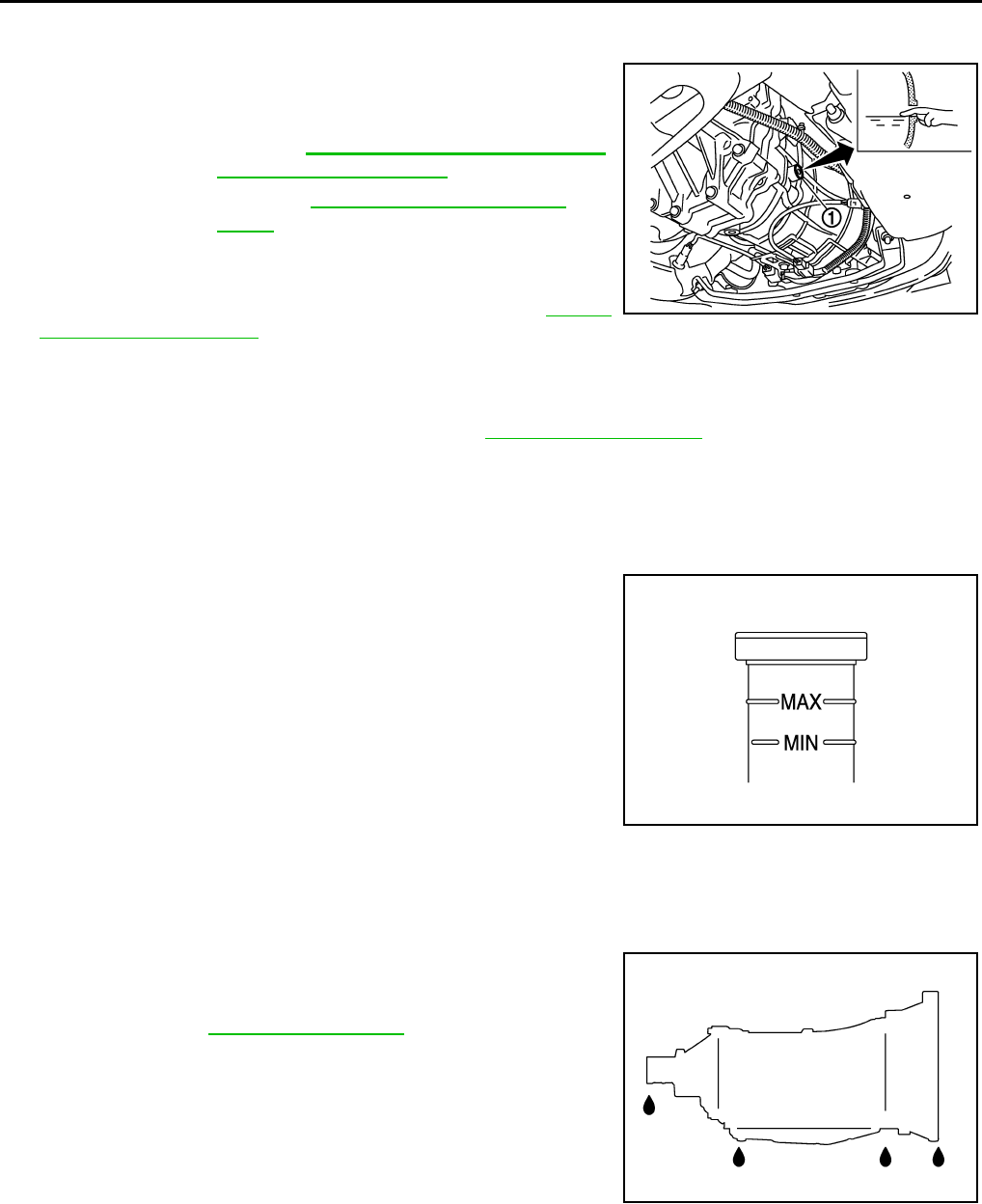
MA-42
< PERIODIC MAINTENANCE >
CHASSIS MAINTENANCE
GEAR OIL : Refilling INFOID:0000000007466315
1. Remove filler plug (1) and gasket from transmission case.
2. Fill with new gear oil to transmission as shown in the figure.
CAUTION:
Never reuse drained gear oil.
3. After refilling gear oil, check the oil level. Refer to MA-41,
"GEAR OIL : Inspection".
4. Set a gasket on filler plug and then install it to transmission case.
CAUTION:
Never reuse gasket.
5. Tighten filler plug to the specified torque. Refer to TM-32, "Exploded View".
CLUTCH FLUID
CLUTCH FLUID : Inspection INFOID:0000000007466316
CLUTCH FLUID LEVEL
• Check that the fluid level in the reservoir tank is within the specified
range (MAX – MIN lines).
• Visually check for any clutch fluid leakage around the reservoir
tank.
• Check the clutch system for any leakage if the fluid level is
extremely low (lower than MIN).
A/T FLUID
A/T FLUID : Inspection INFOID:0000000007797890
FLUID LEAKAGE
• Check transmission surrounding area (oil seal and plug etc.) for
fluid leakage.
• If anything is found, repair or replace damaged parts and adjust A/
T fluid level. Refer to TM-259, "Adjustment".
TRANSFER FLUID
TRANSFER FLUID : Inspection INFOID:0000000007466318
FLUID LEAKAGE
Check transfer surrounding area (oil seal, drain plug, and filler plug etc.) for fluid leakage.
Oil grade and
viscosity : Refer to MA-17, "FOR NORTH AMERICA
: Fluids and Lubricants".
Oil capacity : Refer to TM-94, "General Specifica-
tions".
JPDIC0590ZZ
JPDIB0032ZZ
JSDIA1912ZZ
Revision: 2013 February 2012 G Sedan
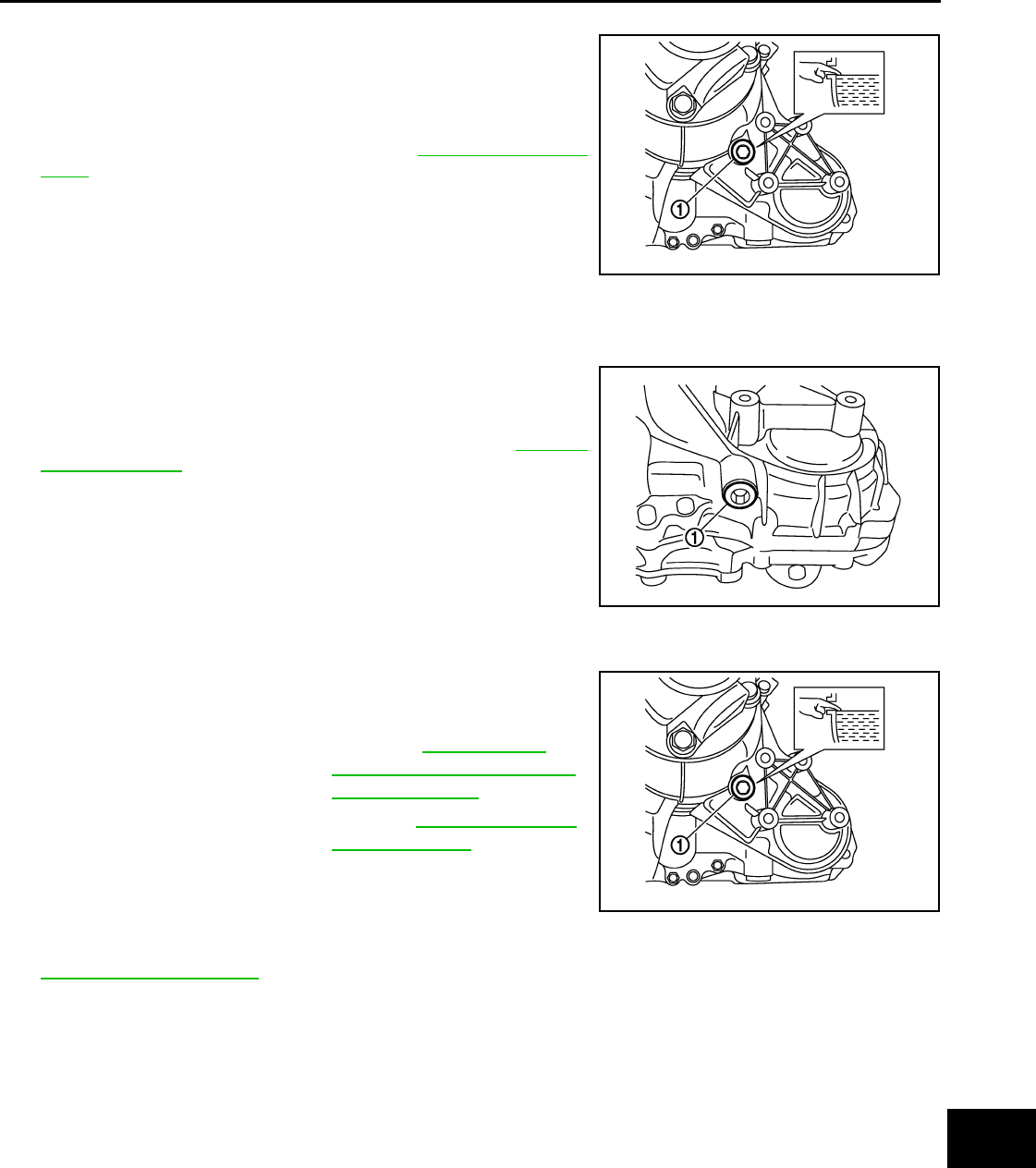
CHASSIS MAINTENANCE
MA-43
< PERIODIC MAINTENANCE >
C
D
E
F
G
H
I
J
K
L
M
B
MA
N
O
A
FLUID LEVEL
1. Remove filler plug (1) and gasket. Then check that fluid is filled
up from mounting hole for the filler plug.
CAUTION:
Never start engine while checking fluid level.
2. Set a new gasket onto filler plug, and install it on transfer and
tighten to the specified torque. Refer to DLN-57, "Exploded
View".
CAUTION:
Never reuse gasket.
TRANSFER FLUID : Draining INFOID:0000000007466319
1. Run the vehicle to warm up the transfer unit sufficiently.
2. Stop the engine, and remove the drain plug (1) to drain the
transfer fluid.
3. Set a new gasket onto the drain plug, and install it on the trans-
fer and tighten to the specified torque. Refer to DLN-57,
"Exploded View".
CAUTION:
Never reuse gasket.
TRANSFER FLUID : Refilling INFOID:0000000007802199
1. Remove filler plug (1) and gasket. Then fill fluid up to mounting
hole for the filler plug.
CAUTION:
Carefully fill the fluid. (Fill up for approximately 3 minutes.)
2. Leave the vehicle for 3 minutes, and check the fluid level again.
3. Set a new gasket onto filler plug, and install it on transfer and tighten to the specified torque. Refer to
DLN-57, "Exploded View".
CAUTION:
Never reuse gasket.
FRONT PROPELLER SHAFT: 2S56A
FRONT PROPELLER SHAFT: 2S56A : Inspection INFOID:0000000007768439
APPEARANCE AND NOISE
• Check the propeller shaft tube surface for dents or cracks. If damaged, replace propeller shaft assembly.
• If center bearing is noisy or damaged, replace propeller shaft assembly.
VIBRATION
If vibration is present at high speed, inspect propeller shaft runout first.
JPDIE0129ZZ
JPDIE0130ZZ
Fluid and viscosity : Refer to MA-17, "FOR
NORTH AMERICA : Fluids
and Lubricants".
Fluid capacity : Refer to DLN-76, "General
Specifications".
JPDIE0129ZZ
Revision: 2013 February 2012 G Sedan
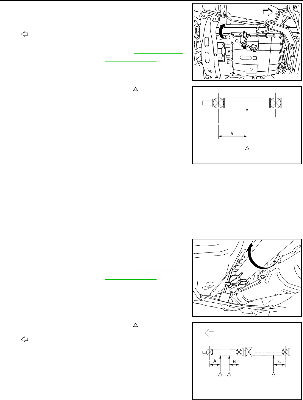
MA-44
< PERIODIC MAINTENANCE >
CHASSIS MAINTENANCE
1. With a dial indicator, measure propeller shaft runout at runout
measuring points by rotating final drive companion flange with
hands.
• Propeller shaft runout measuring point (Point “ ”)
2. If runout still exceeds specifications, separate propeller shaft at
final drive companion flange; then change the phase between
companion flange and propeller shaft by the one bolt hole at a
time and install propeller shaft.
3. Check runout again. If runout still exceeds specifications,
replace propeller shaft assembly.
4. Check the vibration by driving vehicle.
REAR PROPELLER SHAFT: 3S80A
REAR PROPELLER SHAFT: 3S80A : Inspection INFOID:0000000007768440
NOISE
• Check the propeller shaft tube surface for dents or cracks. If damaged, replace propeller shaft assembly.
• If center bearing is noisy or damaged, replace propeller shaft assembly.
VIBRATION
If vibration is present at high speed, inspect propeller shaft runout first.
1. With a dial indicator, measure propeller shaft runout at runout
measuring points by rotating final drive companion flange with
hands.
• Propeller shaft runout measuring point (Point “ ”)
2. If runout still exceeds specifications, separate propeller shaft at
final drive companion flange; then change the phase between
companion flange and propeller shaft by the one bolt hole at a
time and install propeller shaft.
3. Check runout again. If runout still exceeds specifications, replace propeller shaft assembly.
: Vehicle Front
Propeller shaft runout : Refer to DLN-83, "Propel-
ler Shaft Runout".
JPDID0185ZZ
Dimension A: 381.5 mm (15.02 in)
PDIA0768J
Propeller shaft runout : Refer to DLN-91, "Propel-
ler Shaft Runout".
SDIA1087E
: Vehicle Front
Dimension A: 192 mm (7.56 in)
B: 172 mm (6.77 in)
C: 170 mm (6.69 in)
PDIA0770J
Revision: 2013 February 2012 G Sedan
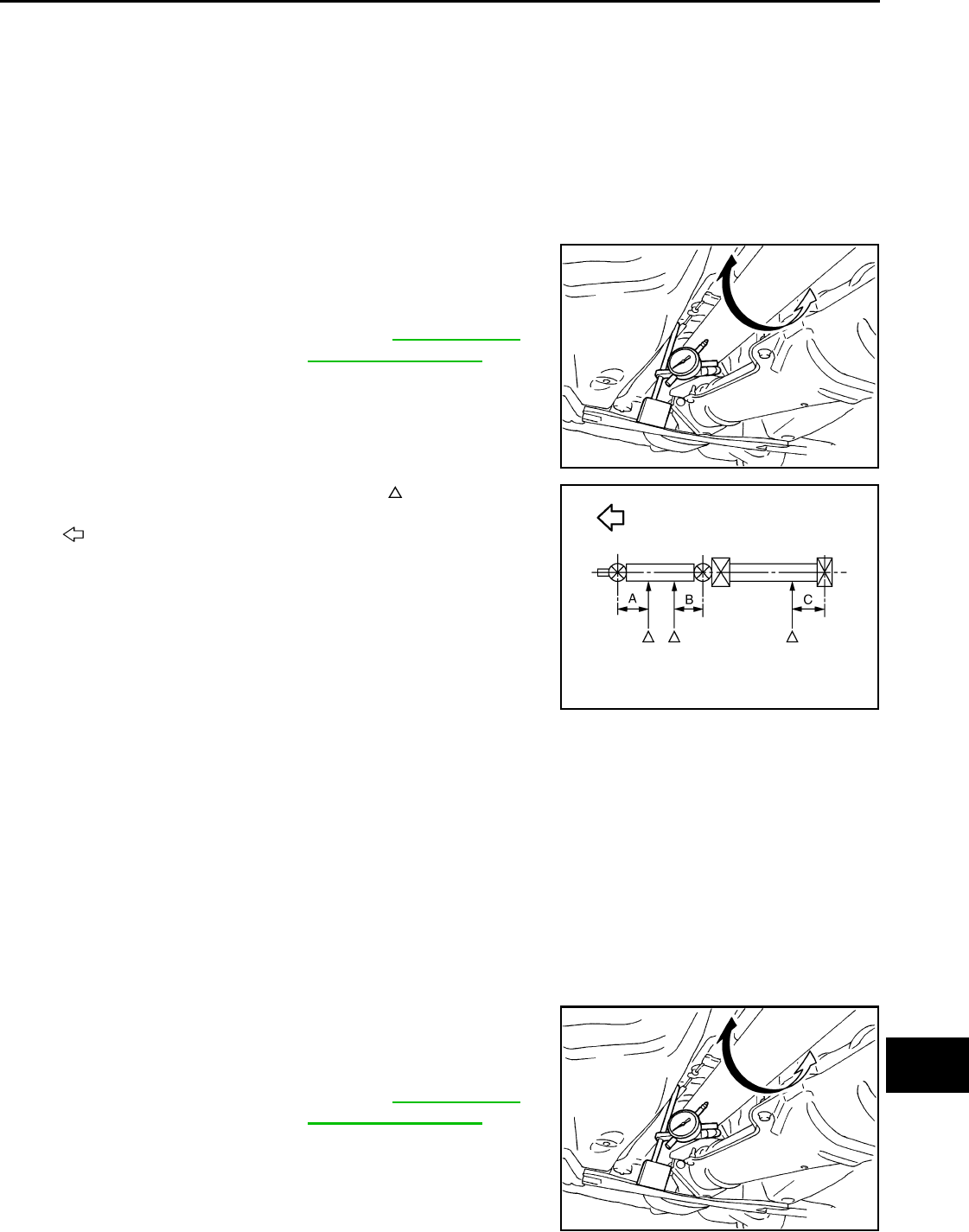
CHASSIS MAINTENANCE
MA-45
< PERIODIC MAINTENANCE >
C
D
E
F
G
H
I
J
K
L
M
B
MA
N
O
A
4. Check the vibration by driving vehicle.
REAR PROPELLER SHAFT: 3S80A-R
REAR PROPELLER SHAFT: 3S80A-R : Inspection INFOID:0000000007768441
NOISE
• Check the propeller shaft tube surface for dents or cracks. If damaged, replace propeller shaft assembly.
• If center bearing is noisy or damaged, replace propeller shaft assembly.
VIBRATION
If vibration is present at high speed, inspect propeller shaft runout first.
1. With a dial indicator, measure propeller shaft runout at runout
measuring points by rotating final drive companion flange with
hands.
• Propeller shaft runout measuring point (Point “ ”)
2. If runout still exceeds specifications, separate propeller shaft at
final drive companion flange; then change the phase between
companion flange and propeller shaft by the one bolt hole at a
time and install propeller shaft.
3. Check runout again. If runout still exceeds specifications, replace propeller shaft assembly.
4. Check the vibration by driving vehicle.
REAR PROPELLER SHAFT: 3F80A-1VL107
REAR PROPELLER SHAFT: 3F80A-1VL107 : Inspection INFOID:0000000007768442
NOISE
• Check the propeller shaft tube surface for dents or cracks. If damaged, replace propeller shaft assembly.
• If center bearing is noisy or damaged, replace propeller shaft assembly.
VIBRATION
If vibration is present at high speed, inspect propeller shaft runout first.
1. With a dial indicator, measure propeller shaft runout at runout
measuring points by rotating final drive companion flange with
hands.
Propeller shaft runout : Refer to DLN-100, "Pro-
peller Shaft Runout".
SDIA1087E
: Vehicle front
Dimension A: 192 mm (7.56 in)
B: 172 mm (6.77 in)
C: 172 mm (6.77 in)
JSDIA0169ZZ
Propeller shaft runout : Refer to DLN-109, "Pro-
peller Shaft Runout".
SDIA1087E
Revision: 2013 February 2012 G Sedan
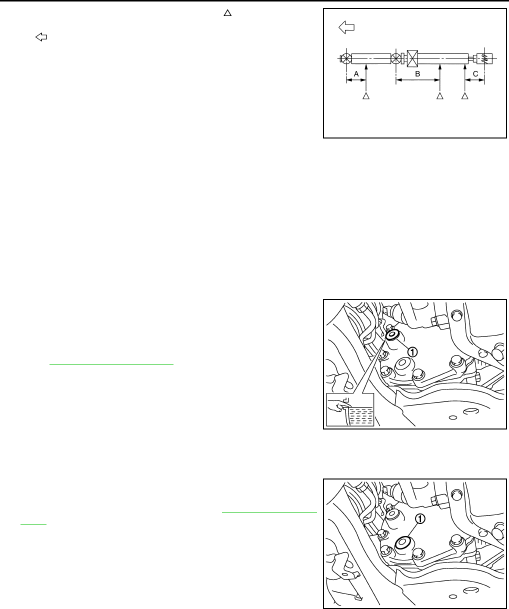
MA-46
< PERIODIC MAINTENANCE >
CHASSIS MAINTENANCE
• Propeller shaft runout measuring point (Point “ ”)
2. If runout still exceeds specifications, separate propeller shaft at
final drive companion flange or transfer companion flange; then
change the phase between companion flange and propeller shaft by the one bolt hole at a time and install
propeller shaft.
3. Check runout again. If runout still exceeds specifications, replace propeller shaft assembly.
4. Check the vibration by driving vehicle.
FRONT DIFFERENTIAL GEAR OIL: F160A
FRONT DIFFERENTIAL GEAR OIL: F160A : Inspection INFOID:0000000007768443
OIL LEAKAGE
Make sure that oil is not leaking from final drive assembly or around it.
OIL LEVEL
• Remove filler plug (1) and check oil level from filler plug mounting
hole as shown in the figure.
CAUTION:
Never start engine while checking oil level.
• Set a gasket on filler plug and install it on final drive assembly.
Refer to DLN-123, "Exploded View".
CAUTION:
Never reuse gasket.
FRONT DIFFERENTIAL GEAR OIL: F160A : Draining INFOID:0000000007768444
1. Stop engine.
2. Remove drain plug (1) and drain gear oil.
3. Set a gasket on drain plug and install it to final drive assembly
and tighten to the specified torque. Refer to DLN-123, "Exploded
View".
CAUTION:
Never reuse gasket.
: Vehicle front
Standard
A : 162 mm (6.38 in)
B : 245 mm (9.65 in)
C : 185 mm (7.28 in)
PDIA0772J
JPDID0188ZZ
JPDID0189ZZ
Revision: 2013 February 2012 G Sedan
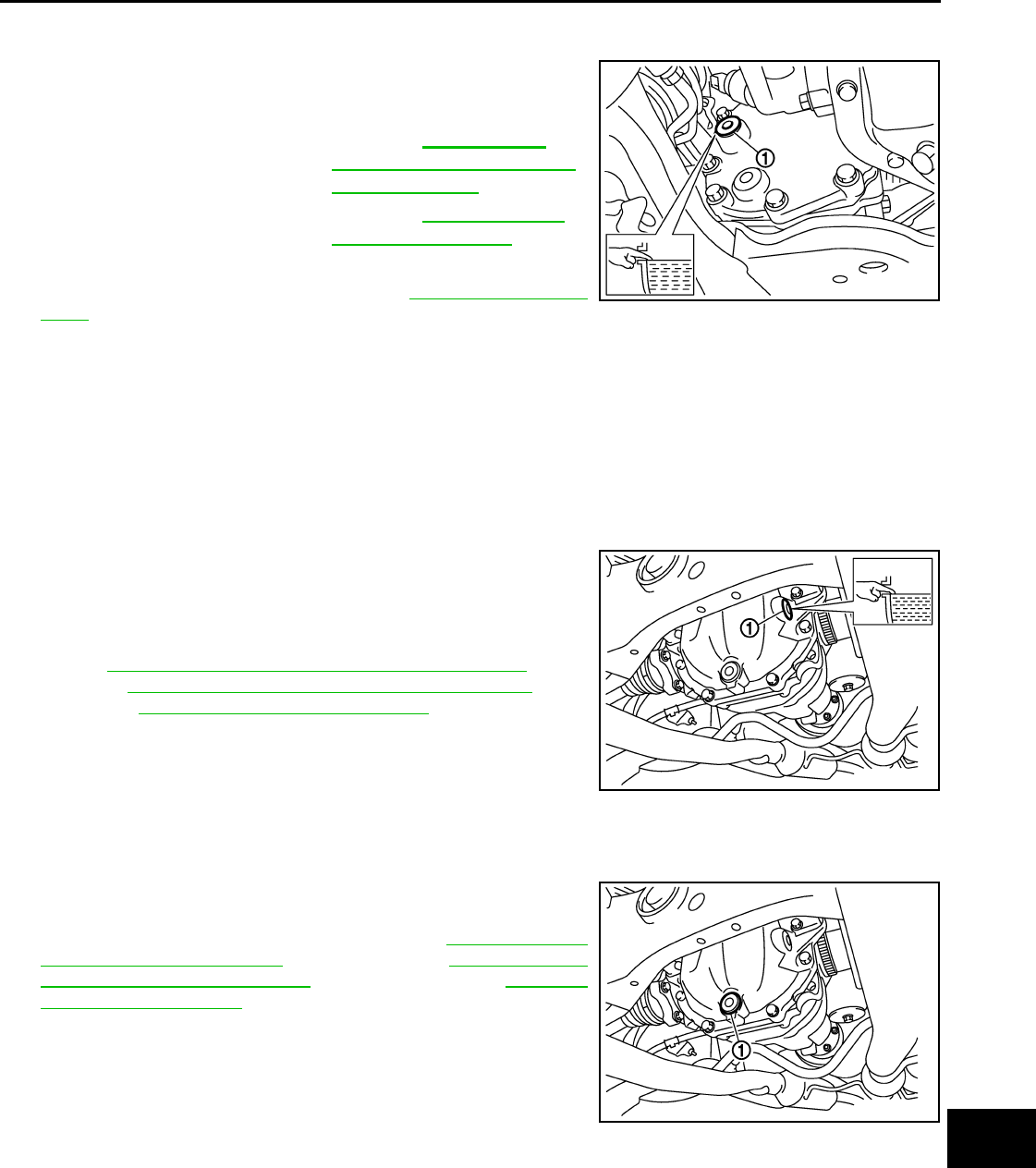
CHASSIS MAINTENANCE
MA-47
< PERIODIC MAINTENANCE >
C
D
E
F
G
H
I
J
K
L
M
B
MA
N
O
A
FRONT DIFFERENTIAL GEAR OIL: F160A : Refilling INFOID:0000000007802200
1. Remove filler plug (1). Fill with new gear oil until oil level reaches
the specified level near filler plug mounting hole.
2. After refilling oil, check oil level. Set a gasket to filler plug, then
install it to final drive assembly. Refer to DLN-123, "Exploded
View".
CAUTION:
Never reuse gasket.
REAR DIFFERENTIAL GEAR OIL: R200
REAR DIFFERENTIAL GEAR OIL: R200 : Inspection INFOID:0000000007768446
OIL LEAKAGE
Make sure that oil is not leaking from final drive assembly or around it.
OIL LEVEL
• Remove filler plug (1) and check oil level from filler plug mounting
hole as shown in the figure.
CAUTION:
Never start engine while checking oil level.
• Set a gasket on filler plug and install it on final drive assembly.
Refer to DLN-188, "2WD (VQ25HR) : Exploded View" [2WD
(VQ25HR)], DLN-200, "2WD (VQ37VHR) : Exploded View" [2WD
(VQ37VHR)], DLN-213, "AWD : Exploded View" (AWD).
CAUTION:
Never reuse gasket.
REAR DIFFERENTIAL GEAR OIL: R200 : Draining INFOID:0000000007768447
1. Stop the engine.
2. Remove drain plug (1) and drain gear oil.
3. Set a gasket on drain plug and install it to final drive assembly
and tighten to the specified torque. Refer to DLN-188, "2WD
(VQ25HR) : Exploded View" [2WD (VQ25HR)], DLN-200, "2WD
(VQ37VHR) : Exploded View" [2WD (VQ37VHR)], DLN-213,
"AWD : Exploded View" (AWD).
CAUTION:
Never reuse gasket.
Oil grade and Viscosity : Refer to MA-17, "FOR
NORTH AMERICA : Fluids
and Lubricants".
Oil capacity : Refer to DLN-148, "Gen-
eral Specifications".
JPDID0188ZZ
JPDID0190ZZ
JPDID0191ZZ
Revision: 2013 February 2012 G Sedan
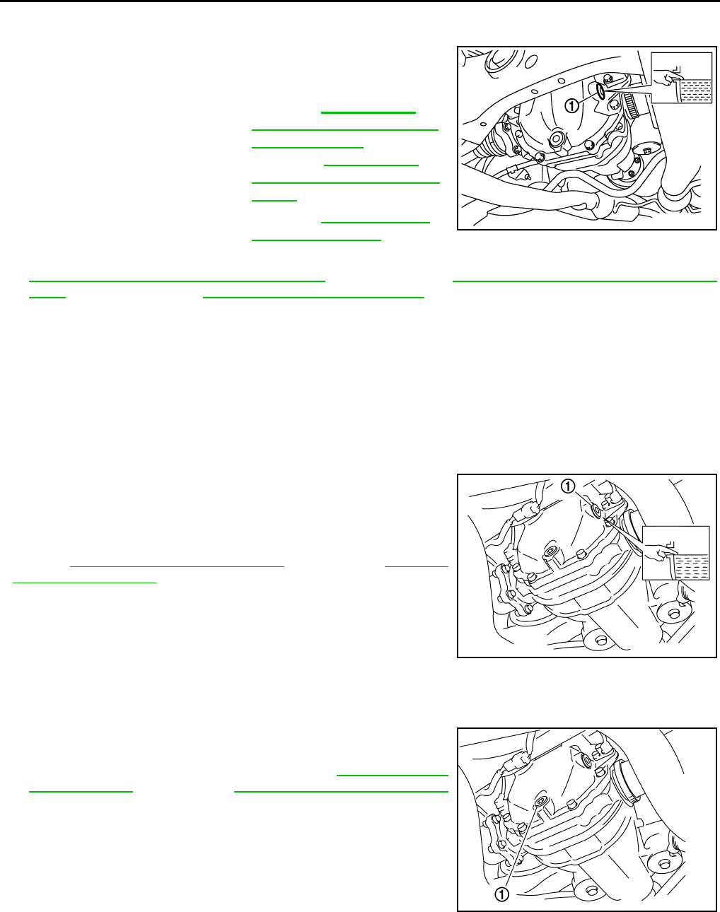
MA-48
< PERIODIC MAINTENANCE >
CHASSIS MAINTENANCE
REAR DIFFERENTIAL GEAR OIL: R200 : Refilling INFOID:0000000007802201
1. Remove filler plug (1). Fill with new gear oil until oil level reaches
the specified level near filler plug mounting hole.
2. After refilling oil, check oil level. Set a gasket to filler plug, then install it to final drive assembly. Refer to
DLN-188, "2WD (VQ25HR) : Exploded View" [2WD (VQ25HR)], DLN-200, "2WD (VQ37VHR) : Exploded
View" [2WD (VQ37VHR)], DLN-213, "AWD : Exploded View" (AWD).
CAUTION:
Never reuse gasket.
REAR DIFFERENTIAL GEAR OIL: R200V
REAR DIFFERENTIAL GEAR OIL: R200V : Inspection INFOID:0000000007768449
OIL LEAKAGE
• Make sure that oil is not leaking from final drive assembly or around it.
OIL LEVEL
• Remove filler plug (1) and check oil level from filler plug mounting
hole as shown in the figure.
CAUTION:
Never start engine while checking oil level.
• Set a gasket on filler plug and install it on final drive assembly.
Refer to DLN-279, "M/T : Exploded View" (M/T models), DLN-291,
"A/T : Exploded View" (A/T models).
CAUTION:
Never reuse gasket.
REAR DIFFERENTIAL GEAR OIL: R200V : Draining INFOID:0000000007768450
1. Stop engine.
2. Remove drain plug (1) and drain gear oil.
3. Set a gasket on drain plug and install it to final drive assembly
and tighten to the specified torque. Refer to DLN-279, "M/T :
Exploded View" (M/T models), DLN-291, "A/T : Exploded View"
(A/T models).
CAUTION:
Never reuse gasket.
Oil grade and viscosity : Refer to MA-17, "FOR
NORTH AMERICA : Fluids
and Lubricants" (For North
America), MA-19, "FOR
MEXICO : Fluids and Lubri-
cants" (For Mexico).
Oil capacity : Refer to DLN-250, "Gen-
eral Specification".JPDID0190ZZ
PDIA0749J
PDIA0748J
Revision: 2013 February 2012 G Sedan
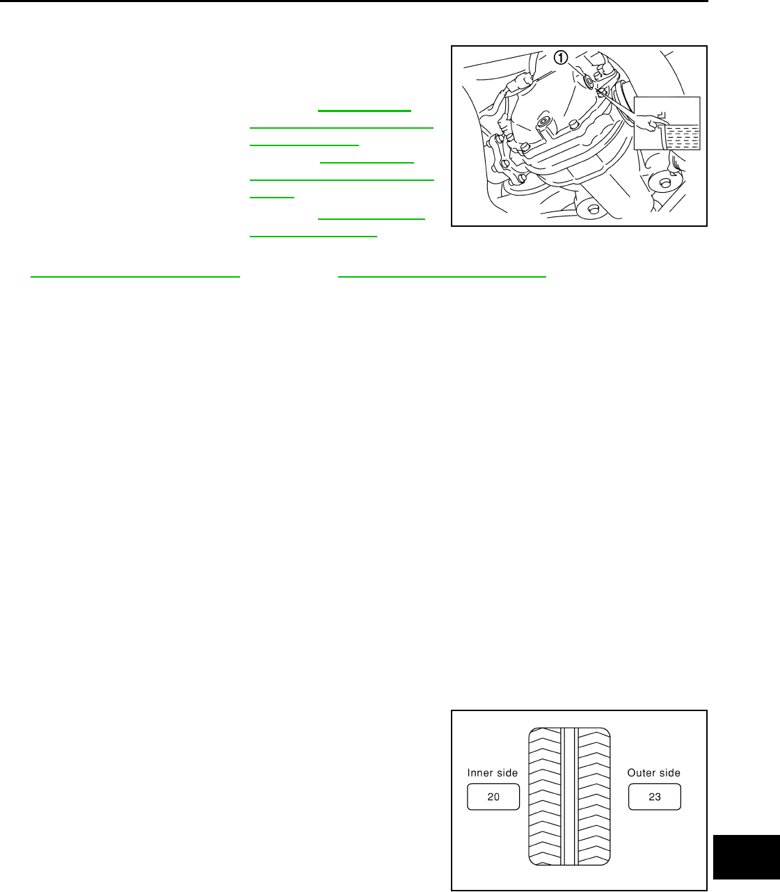
CHASSIS MAINTENANCE
MA-49
< PERIODIC MAINTENANCE >
C
D
E
F
G
H
I
J
K
L
M
B
MA
N
O
A
REAR DIFFERENTIAL GEAR OIL: R200V : Refilling INFOID:0000000007802202
1. Remove filler plug (1). Fill with new gear oil until oil level reaches
the specified level near filler plug mounting hole.
2. After refilling oil, check oil level. Set a gasket to filler plug, then install it to final drive assembly. Refer to
DLN-279, "M/T : Exploded View" (M/T models), DLN-291, "A/T : Exploded View" (A/T models).
CAUTION:
Never reuse gasket.
WHEELS (BONDING WEIGHT TYPE)
WHEELS (BONDING WEIGHT TYPE) : Adjustment INFOID:0000000007768452
BALANCING WHEELS (BONDING WEIGHT TYPE)
Preparation Before Adjustment
Using releasing agent, remove double-faced adhesive tape from the road wheel.
CAUTION:
• Be careful not scratch the road wheel during removal.
• After removing double-faced adhesive tape, wipe clean traces of releasing agent from the road
wheel.
Wheel Balance Adjustment
• If a tire balance machine has adhesion balance weight mode settings and drive-in weight mode setting,
select and adjust a drive-in weight mode suitable for road wheels.
1. Set road wheel on tire balance machine using the center hole as a guide. Start the tire balance machine.
2. When inner and outer unbalance values are shown on the tire balance machine indicator, multiply outer
unbalance value by 5/3 to determine balance weight that should be used. Select the outer balance weight
with a value closest to the calculated value above and install in to the designated outer position of, or at
the designated angle in relation to the road wheel.
CAUTION:
• Never install the inner balance weight before installing the outer balance weight.
• Before installing the balance weight, be sure to clean the mating surface of the road wheel.
a. Indicated un balance value × 5/3 = balance weight to be
installed
Calculation example:
23 g (0.81 oz) × 5/3 = 38.33 g (1.35 oz) ⇒ 37.5 g (1.32 oz) bal-
ance weight (closer to calculated balance weight value)
NOTE:
Note that balance weight value must be closer to the calculated
balance weight value.
Example:
36.2 ⇒ 35 g (1.23 oz)
36.3 ⇒ 37.5 g (1.32 oz)
b. Installed balance weight in the position.
Oil grade and viscosity : Refer to MA-17, "FOR
NORTH AMERICA : Fluids
and Lubricants" (For North
America), MA-19, "FOR
MEXICO : Fluids and Lubri-
cants" (For Mexico).
Oil capacity : Refer to DLN-320, "Gen-
eral Specification".PDIA0749J
SMA054D
Revision: 2013 February 2012 G Sedan
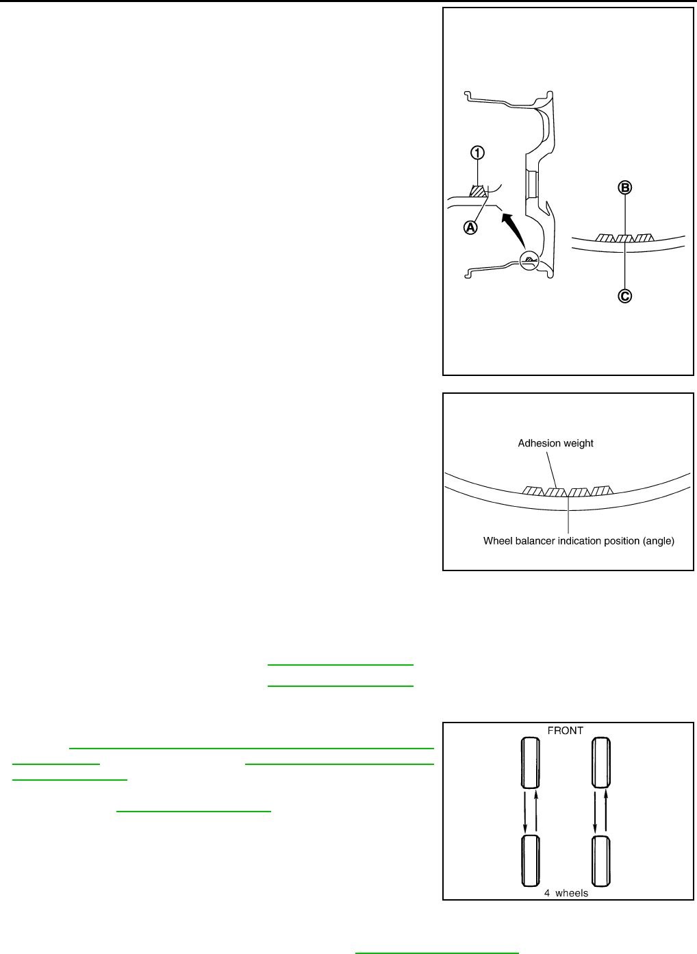
MA-50
< PERIODIC MAINTENANCE >
CHASSIS MAINTENANCE
• When installing balance weight (1) to road wheels, set it into
the grooved area (A) on the inner wall of the road wheel as
shown in the figure so that the balance weight center (B) is
aligned with the tire balance machine indication position
(angle) (C).
CAUTION:
• Always use genuine NISSAN adhesion balance weights.
• Balance weights are non-reusable; always replace with
new ones.
• Never install more than three sheets of balance weight.
c. If calculated balance weight value exceeds 50 g (1.76 oz), install
two balance weight sheets in line with each other as shown in
the figure.
CAUTION:
Never install one balance weight sheet on top another.
3. Start tire balance machine again.
4. Install drive-in balance weight on inner side of road wheel in the
tire balance machine indication position (angle).
CAUTION:
Never install more than two balance weight.
5. Start tire balance machine. Make sure that inner and outer resid-
ual unbalance values are 5 g (0.17 oz) each or below.
6. If either residual unbalance value exceeds 5 g (0.17 oz), repeat installation procedures.
TIRE ROTATION (for 17 and 18 inch wheel models)
• Follow the maintenance schedule for tire rotation service intervals.
Refer to MA-5, "FOR NORTH AMERICA : Explanation of General
Maintenance" (For North America), MA-7, "FOR MEXICO : Gen-
eral Maintenance" (For Mexico).
• When installing the wheel, tighten wheel nuts to the specified
torque. Refer to WT-44, "Exploded View".
CAUTION:
• Never include the T-type spare tire when rotating the tires.
• When installing wheels, tighten them diagonally by dividing
the work two to three times in order to prevent the wheels
from developing any distortion.
• Be careful not to tighten wheel nut at torque exceeding the
criteria for preventing strain of disc rotor.
• Use NISSAN genuine wheel nuts for aluminum wheels.
• Perform the ID registration, after tire rotation. Refer to WT-18, "Work Procedure".
JPEIC0040ZZ
Limit
Dynamic (At flange) : Refer to WT-49, "Road Wheel".
Static (At flange) : Refer to WT-49, "Road Wheel".
PEIA0033E
SMA829C
Revision: 2013 February 2012 G Sedan
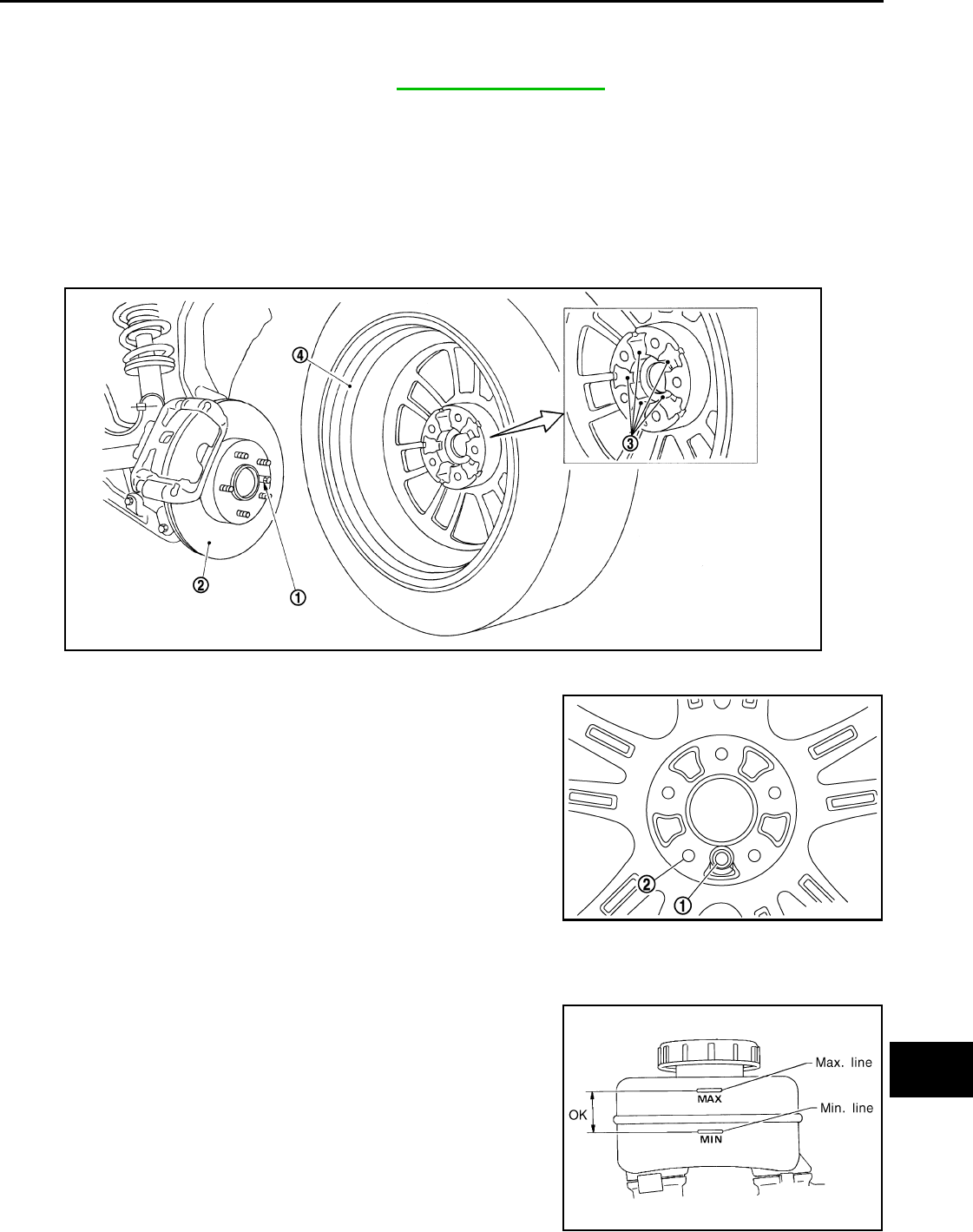
CHASSIS MAINTENANCE
MA-51
< PERIODIC MAINTENANCE >
C
D
E
F
G
H
I
J
K
L
M
B
MA
N
O
A
TIRE ROTATION (for 18 inch front and rear different tire size models)
• Tire cannot be rotated in vehicle, as front tire are different size from rear tire is fixed in each tire.
CAUTION:
• Never include the T-type spare tire when rotating the tires.
• Use NISSAN genuine wheel nuts for aluminum wheels.
Safety Device Preventing from Being Incorrectly installed
FRONT BRAKE DISC ROTOR AND FRONT WHEEL
• Front and rear wheel size for this model differs, therefore special pin (1) is adopted to the front brake disc
rotor (2). And a hole (3) that matches to this pin is adopted to the front wheel (4) (the rear wheel does not
have this wheel). This structure prevents the rear wheel from being mistakenly installed on the front.
T-TYPE SPARE TIRE WHEEL
• Regarding spare tire (for emergency) wheel, wrong assembly pro-
tection pin hole (1) has been set in addition to regular bolt holes (2)
in order to enable installation to front wheel.
BRAKE FLUID LEVEL AND LEAKS
BRAKE FLUID LEVEL AND LEAKS : Inspection INFOID:0000000007466335
• If fluid level is extremely low, check brake system for leaks.
Wheel nuts tighting torque : Refer to WT-44, "Exploded View".
JPEIC0015ZZ
JSEIA0381ZZ
SBR451D
Revision: 2013 February 2012 G Sedan
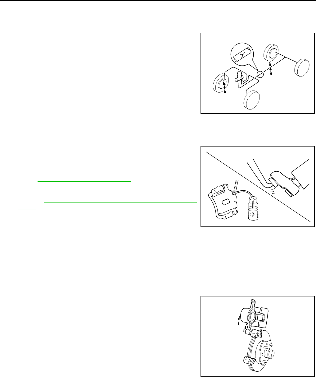
MA-52
< PERIODIC MAINTENANCE >
CHASSIS MAINTENANCE
BRAKE LINES AND CABLES
BRAKE LINES AND CABLES : Inspection INFOID:0000000007466336
• Check brake fluid lines and parking brake cables for improper
attachment, leaks, chafing, abrasions, deterioration, etc.
BRAKE FLUID
BRAKE FLUID : Changing INFOID:0000000007466337
1. Drain brake fluid from each bleed valve.
2. Refill until new brake fluid comes out from each bleed valve.
Use same procedure as in bleeding hydraulic system to refill
brake fluid.
Refer to BR-11, "Bleeding Brake System".
• Refill with recommended Genuine NISSAN Super Heavy Duty
Brake Fluid or equivalent DOT 3 (US FMVSS No. 116).
Refer to MA-17, "FOR NORTH AMERICA : Fluids and Lubri-
cants".
• Never reuse drained brake fluid.
• Be careful not to splash brake fluid on painted areas.
DISC BRAKE
DISC BRAKE : Inspection INFOID:0000000007466338
DISC ROTOR
Check condition, wear, and damage.
CALIPER
• Check for leakage.
BRAKE PAD
SBR389C
SBR419C
SMA922A
Revision: 2013 February 2012 G Sedan
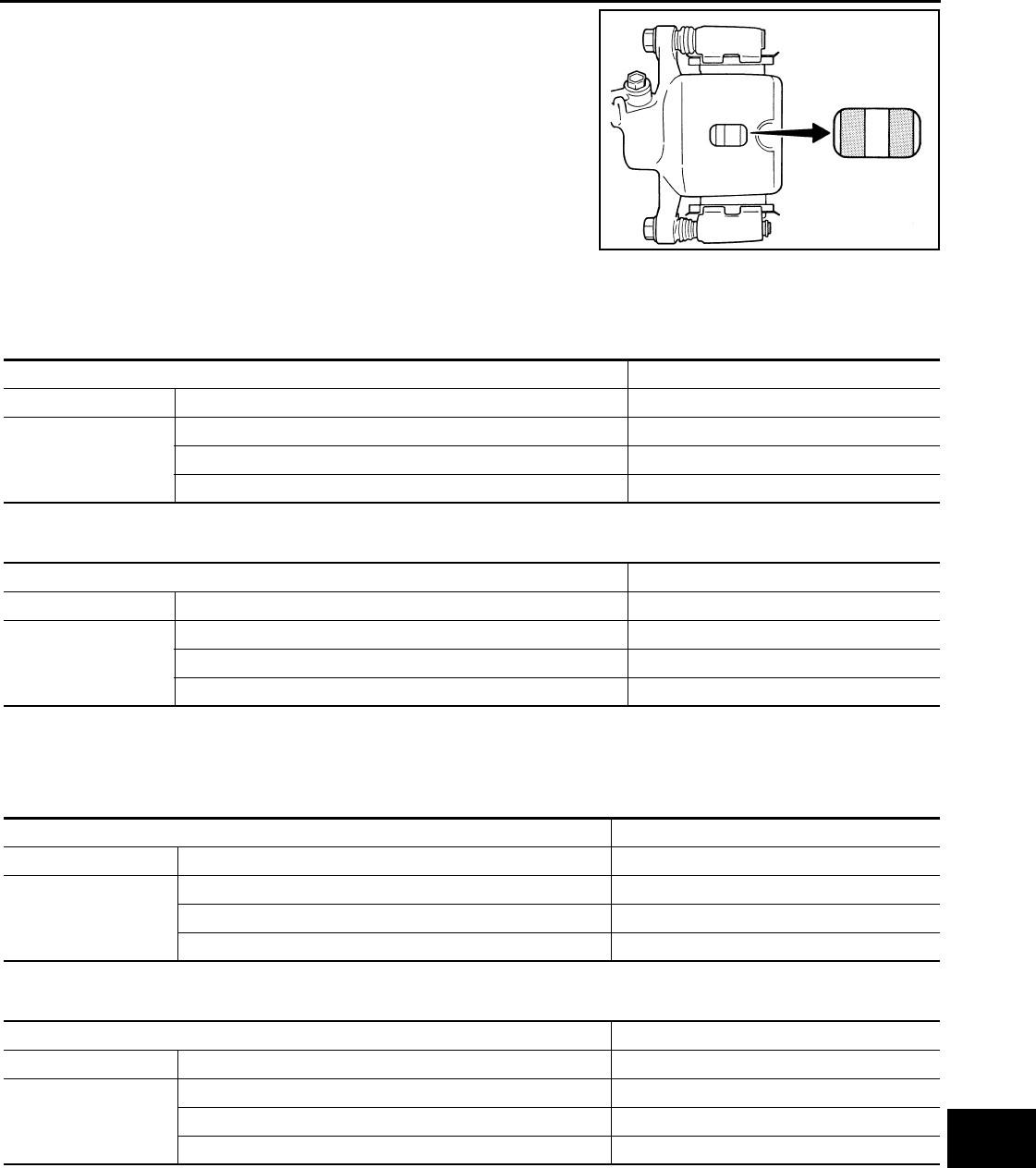
CHASSIS MAINTENANCE
MA-53
< PERIODIC MAINTENANCE >
C
D
E
F
G
H
I
J
K
L
M
B
MA
N
O
A
• Check for wear or damage.
DISC BRAKE : Front Disc Brake INFOID:0000000007466339
2 PISTON TYPE
Unit: mm (in)
4 PISTON TYPE
Unit: mm (in)
DISC BRAKE : Rear Disc Brake INFOID:0000000007466340
1 PISTON TYPE
Unit: mm (in)
2 PISTON TYPE
Unit: mm (in)
STEERING GEAR AND LINKAGE
STEERING GEAR AND LINKAGE : Inspection INFOID:0000000007466341
STEERING GEAR
BRA0010D
Item Limit
Brake pad Wear thickness 2.0 (0.079)
Disc rotor
Wear thickness 26.0 (1.024)
Thickness variation (measured at 8 positions) 0.015 (0.0006)
Runout (with it attached to the vehicle) 0.035 (0.0014)
Item Limit
Brake pad Wear thickness 2.0 (0.079)
Disc rotor
Wear thickness 30.0 (1.181)
Thickness variation (measured at 8 positions) 0.015 (0.0006)
Runout (with it attached to the vehicle) 0.035 (0.0014)
Item Limit
Brake pad Wear thickness 2.0 (0.079)
Disc rotor
Wear thickness 14.0 (0.551)
Thickness variation (measured at 8 positions) 0.015 (0.0006)
Runout (with it attached to the vehicle) 0.055 (0.0022)
Item Limit
Brake pad Wear thickness 2.0 (0.079)
Disc rotor
Wear thickness 18.0 (0.709)
Thickness variation (measured at 8 positions) 0.015 (0.0006)
Runout (with it attached to the vehicle) 0.055 (0.0022)
Revision: 2013 February 2012 G Sedan
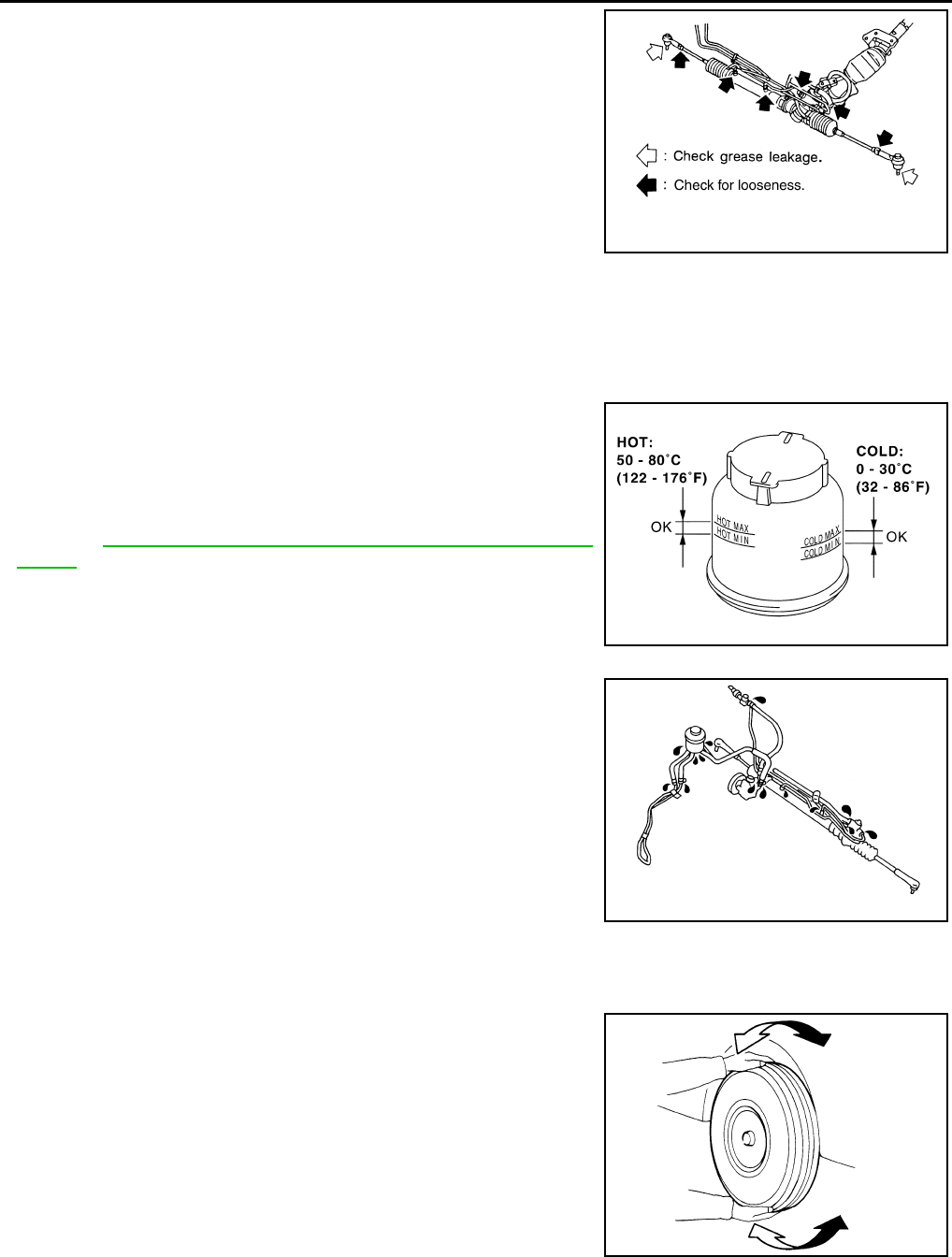
MA-54
< PERIODIC MAINTENANCE >
CHASSIS MAINTENANCE
• Check gear housing and boots for looseness, damage and grease
leakage.
• Check connection with steering column for looseness.
STEERING LINKAGE
Check ball joint, dust cover and other component parts for looseness, wear, damage and grease leakage.
POWER STEERING FLUID AND LINES
POWER STEERING FLUID AND LINES : Inspection INFOID:0000000007466342
Check fluid level in reservoir tank with engine off.
Use “HOT” range at fluid temperatures of 50 to 80°C (122 to 176°F)
or “COLD” range at fluid temperatures of 0 to 30°C (32 to 86°F).
CAUTION:
• Do not overfill.
• Recommended fluid is Genuine NISSAN PSF or equivalent.
Refer to MA-17, "FOR NORTH AMERICA : Fluids and Lubri-
cants".
• Check lines for improper attachment, leaks, cracks, damage,
loose connections, chafing and deterioration.
• Check rack boots for accumulation of power steering fluid.
AXLE AND SUSPENSION PARTS
AXLE AND SUSPENSION PARTS : Inspection INFOID:0000000007466343
Check front and rear axle and suspension parts for excessive play,
cracks, wear or other damage.
• Shake each wheel to check for excessive play.
• Check wheel bearings for smooth operation.
• Check axle and suspension nuts and bolts for looseness.
• Check strut (shock absorber) for oil leakage or other damage.
• Check suspension ball joint for grease leakage and ball joint dust
cover for cracks or other damage.
SLIA0014E
SST850C
SST851C
SMA525A
Revision: 2013 February 2012 G Sedan
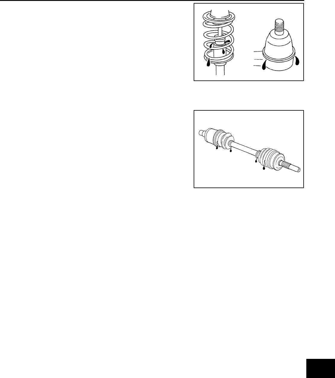
CHASSIS MAINTENANCE
MA-55
< PERIODIC MAINTENANCE >
C
D
E
F
G
H
I
J
K
L
M
B
MA
N
O
A
DRIVE SHAFT
DRIVE SHAFT : Inspection INFOID:0000000007466344
Check boot and drive shaft for cracks, wear, damage and grease
leakage.
JPPIA0011ZZ
SFA108A
Revision: 2013 February 2012 G Sedan
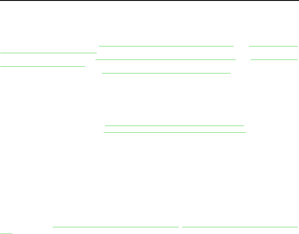
MA-56
< PERIODIC MAINTENANCE >
BODY MAINTENANCE
BODY MAINTENANCE
LOCKS, HINGES AND HOOD LATCH
LOCKS, HINGES AND HOOD LATCH : Lubricating INFOID:0000000007466345
For hood lock illustration. Refer to DLK-198, "HOOD ASSEMBLY : Exploded View" and DLK-201, "HOOD
LOCK CONTROL : Exploded View".
For door lock illustration. Refer to DLK-214, "FRONT DOOR LOCK : Exploded View" and DLK-217, "REAR
DOOR LOCK : Exploded View".
For trunk lid lock illustration. Refer to DLK-223, "TRUNK LID LOCK : Exploded View".
SEAT BELT, BUCKLES, RETRACTORS, ANCHORS AND ADJUSTERS
SEAT BELT, BUCKLES, RETRACTORS, ANCHORS AND ADJUSTERS : Inspection
INFOID:0000000007466346
For front seat belt illustration. Refer to SB-6, "SEAT BELT RETRACTOR : Exploded View".
For rear seat belt illustration. Refer to SB-11, "SEAT BELT RETRACTOR : Exploded View".
CAUTION:
• After any collision, inspect all seat belt assemblies, including retractors and other attached hard-
wares (I.e. anchor bolt, guide rail set). Nissan recommends to replace all seat belt assemblies in use
during a collision, unless not damaged and properly operating after minor collision.
Also inspect seat belt assemblies not in use during a collision, and replace if damaged or improperly
operating.
Seat belt pre-tensioner should be replaced even if the seat belts are not in use during a frontal colli-
sion where the driver and passenger air bags are deployed.
• If any component of seat belt assembly is questionable, do not repair.
Replace as seat belt assembly.
• If webbing is cut, frayed, or damaged, replace belt assembly.
• Never oil tongue and buckle.
• Use a genuine NISSAN seat belt assembly.
For details, refer to SB-4, "SEAT BELT RETRACTOR : Inspection", SB-9, "SEAT BELT RETRACTOR : Inspec-
tion" in SB section.
• Check anchors for loose mounting
• Check belts for damage
• Check retractor for smooth operation
• Check function of buckles and tongues when buckled and released
Revision: 2013 February 2012 G Sedan
SERVICE DATA AND SPECIFICATIONS (SDS)
MA-57
< SERVICE DATA AND SPECIFICATIONS (SDS)
C
D
E
F
G
H
I
J
K
L
M
B
MA
N
O
A
SERVICE DATA AND SPECIFICATIONS (SDS)
SERVICE DATA AND SPECIFICATIONS (SDS)
DRIVE BELT (VQ37VHR)
DRIVE BELT (VQ37VHR) : Drive Belt INFOID:0000000007466347
DRIVE BELT
DRIVE BELT (VQ25HR)
DRIVE BELT (VQ25HR) : Drive Belt INFOID:0000000007466348
DRIVE BELT
ENGINE COOLANT
ENGINE COOLANT : Periodical Maintenance Specification INFOID:0000000007466349
ENGINE COOLANT CAPACITY (APPROXIMATE)
Unit: (US qt, Imp qt)
ENGINE OIL
ENGINE OIL : Periodical Maintenance Specification INFOID:0000000007797881
ENGINE OIL CAPACITY (APPROXIMATE)
Unit: (US qt, lmp qt)
SPARK PLUG (VQ37VHR)
Tension of drive belt Belt tension is not necessary, as it is automatically adjusted by drive belt auto-tensioner.
PART Belt spec
Tension [N (kg)] Belt tension (mm)
[When pushed at 98.1N (10 Kg)]
New Adjustment Rimit of
retghten-
ing
New Adjustment Rimit of
retghten-
ing
Alternator · power
steering oil pump
belt
V-ribbed belt
(6 ribbs)
838 - 926
(85.5 - 94.5)
730 - 818
(74.5 - 83.5)
294
(30) 6-7 7-8 12
A/C compressor
belt
V-ribbed belt
(4 ribbs)
470 - 559
(48 - 57)
348 - 436
(35.5 - 4.5)
196
(20) 8-9 9-10 12
Engine coolant capacity [With reservoir tank (“MAX” level)]
VQ25HR 2WD models 8.3 (8-6/8, 7-2/8)
AWD models 8.8 (9-2/8, 7-6/8)
VQ37VHR A/T models 8.5 (9, 7-1/2)
M/T models 8.6 (9-1/8, 7-5/8)
Reservoir tank engine coolant capacity (At “MAX” level) 0.8 (7/8, 3/4)
Drain and refill
VQ25HR With oil filter change 4.7 (5, 4-1/8)
Without oil filter change 4.4 (4-5/8, 3-7/8)
VQ37VHR With oil filter change 4.9 (5-1/8, 4-1/4)
Without oil filter change 4.6 (4-7/8, 4)
Dry engine (Overhaul) VQ25HR 5.4 (5-6/8, 4-6/8)
VQ37VHR 5.7 (6, 5)
Revision: 2013 February 2012 G Sedan
MA-58
< SERVICE DATA AND SPECIFICATIONS (SDS)
SERVICE DATA AND SPECIFICATIONS (SDS)
SPARK PLUG (VQ37VHR) : Spark Plug INFOID:0000000007466351
SPARK PLUG
Unit: mm (in)
SPARK PLUG (VQ25HR)
SPARK PLUG (VQ25HR) : Spark Plug INFOID:0000000007466352
SPARK PLUG
Unit: mm (in)
ROAD WHEEL
ROAD WHEEL : Road Wheel INFOID:0000000007768453
ALUMINUM WHEEL (CONVENTIONAL)
STEEL WHEEL (FOR EMERGENCY USE)
Make DENSO
Standard type FXE24HR11
Gap (Nominal) 1.1 (0.043)
Make DENSO
Standard type FXE22HR11
Gap Standard 1.1 (0.043)
Limit 1.4 (0.055)
Item Limit
Runout Axial runout Less than 0.3 mm (0.012 in)
Radial runout
Allowable unbalance Dynamic (At flange) Less than 5 g (0.17 oz) (one side)
Static (At flange) Less than 10 g (0.35 oz)
Item Limit
Runout Axial runout (Average) Less than 1.5 mm (0.059 in)
Radial runout (Average)
Revision: 2013 February 2012 G Sedan
