Infiniti 2015 Qx60 Maintenance Manual Config(MA)
2015-10-23
: Infiniti Infiniti-2015-Infiniti-Qx60-Maintenance-Manual-817299 infiniti-2015-infiniti-qx60-maintenance-manual-817299 infiniti pdf
Open the PDF directly: View PDF ![]() .
.
Page Count: 44
- QUICK REFERENCE INDEX
- Table of Contents
- PRECAUTION
- PREPARATION
- PERIODIC MAINTENANCE
- GENERAL MAINTENANCE
- PERIODIC MAINTENANCE
- RECOMMENDED FLUIDS AND LUBRICANTS
- ENGINE MAINTENANCE (VQ35DE)
- CHASSIS AND BODY MAINTENANCE
- IN-CABIN MICROFILTER
- EXHAUST SYSTEM
- CVT FLUID
- TRANSFER OIL
- REAR DIFFERENTIAL GEAR OIL
- PROPELLER SHAFT
- WHEELS
- BRAKE FLUID LEVEL AND LEAKS
- BRAKE LINES AND CABLES
- BRAKE FLUID
- FRONT BRAKE
- REAR BRAKE
- STEERING GEAR AND LINKAGE
- POWER STEERING FLUID AND LINES
- AXLE AND SUSPENSION PARTS
- DRIVE SHAFT
- LOCKS, HINGES AND HOOD LATCH
- SEAT BELT, BUCKLES, RETRACTORS, ANCHORS AND ADJUSTERS

MA-1
MAINTENANCE
C
D
E
F
G
H
I
J
K
L
M
B
MA
SECTION MA
N
O
A
CONTENTS
MAINTENANCE
PRECAUTION ............................................... 3
PRECAUTIONS ................................................... 3
Precaution for Supplemental Restraint System
(SRS) "AIR BAG" and "SEAT BELT PRE-TEN-
SIONER" ...................................................................3
PREPARATION ............................................ 4
PREPARATION ................................................... 4
Special Service Tool .................................................4
Commercial Service Tool ..........................................4
PERIODIC MAINTENANCE .......................... 5
GENERAL MAINTENANCE ................................ 5
FOR USA AND CANADA ............................................5
FOR USA AND CANADA : Explanation of General
Maintenance ..............................................................5
FOR MEXICO ..............................................................6
FOR MEXICO : General Maintenance ......................7
PERIODIC MAINTENANCE ................................ 9
FOR USA AND CANADA ............................................9
FOR USA AND CANADA : Introduction of Periodic
Maintenance ..............................................................9
FOR MEXICO ............................................................12
FOR MEXICO : Introduction of Periodic Mainte-
nance ......................................................................12
RECOMMENDED FLUIDS AND LUBRI-
CANTS ................................................................15
FOR USA AND CANADA ..........................................15
FOR USA AND CANADA : Fluids and Lubricants ....15
FOR USA AND CANADA : Engine Oil Recom-
mendation ...............................................................16
FOR USA AND CANADA : Engine Coolant Mix-
ture Ratio ................................................................. 16
FOR MEXICO .............................................................16
FOR MEXICO : Fluids and Lubricants .....................16
FOR MEXICO : Engine Coolant Mixture Ratio ........18
ENGINE MAINTENANCE (VQ35DE) ................19
DRIVE BELTS ............................................................19
DRIVE BELTS : Checking Drive Belts .....................19
DRIVE BELTS : Tension Adjustment ......................19
ENGINE COOLANT ...................................................19
ENGINE COOLANT : System Inspection ................19
ENGINE COOLANT : Changing Engine Coolant ....21
FUEL LINES ...............................................................24
FUEL LINES : Inspection .........................................24
AIR CLEANER FILTER .............................................24
AIR CLEANER FILTER : Exploded View ................25
AIR CLEANER FILTER : Removal and Installation
....25
ENGINE OIL ...............................................................25
ENGINE OIL : Inspection .........................................25
ENGINE OIL : Changing Engine Oil ........................26
OIL FILTER ................................................................26
OIL FILTER : Removal and Installation ...................26
SPARK PLUG ............................................................27
SPARK PLUG : Exploded View ...............................28
SPARK PLUG : Removal and Installation ...............28
EVAP VAPOR LINES ................................................29
EVAP VAPOR LINES : Inspection ...........................29
CHASSIS AND BODY MAINTENANCE ...........30
IN-CABIN MICROFILTER ..........................................30
IN-CABIN MICROFILTER : Removal and Installa-
tion ...........................................................................30
EXHAUST SYSTEM ...................................................30
EXHAUST SYSTEM : Inspection ............................30
Revision: August 2014 2015 QX60 NAM

MA-2
CVT FLUID ................................................................ 30
CVT FLUID : Inspection .......................................... 31
CVT FLUID : Changing ........................................... 31
TRANSFER OIL ........................................................ 33
TRANSFER OIL : Inspection .................................. 33
TRANSFER OIL : Draining ..................................... 33
TRANSFER OIL : Refilling ...................................... 33
REAR DIFFERENTIAL GEAR OIL ........................... 34
REAR DIFFERENTIAL GEAR OIL : Inspection ...... 34
REAR DIFFERENTIAL GEAR OIL : Draining ......... 34
REAR DIFFERENTIAL GEAR OIL : Refilling ......... 35
PROPELLER SHAFT ................................................ 35
PROPELLER SHAFT : Inspection .......................... 35
WHEELS ................................................................... 36
WHEELS : Inspection ............................................. 36
WHEELS : Adjustment ........................................... 36
BRAKE FLUID LEVEL AND LEAKS ........................ 38
BRAKE FLUID LEVEL AND LEAKS : Inspection ... 38
BRAKE LINES AND CABLES .................................. 38
BRAKE LINES AND CABLES : Inspection ............. 39
BRAKE FLUID .......................................................... 39
BRAKE FLUID : Drain and Refill ............................ 39
FRONT BRAKE ......................................................... 40
FRONT BRAKE : Inspection of Pad ........................ 40
FRONT BRAKE : Inspection of Rotor ..................... 40
REAR BRAKE ........................................................... 40
REAR BRAKE : Inspection of Pad .......................... 40
REAR BRAKE : Inspection of Rotor ........................ 40
STEERING GEAR AND LINKAGE ........................... 41
STEERING GEAR AND LINKAGE : Inspection ...... 41
POWER STEERING FLUID AND LINES .................. 41
POWER STEERING FLUID AND LINES : Inspec-
tion .......................................................................... 41
AXLE AND SUSPENSION PARTS ........................... 42
AXLE AND SUSPENSION PARTS : Inspection ..... 42
DRIVE SHAFT ........................................................... 42
DRIVE SHAFT : Inspection ..................................... 43
LOCKS, HINGES AND HOOD LATCH ..................... 43
LOCKS, HINGES AND HOOD LATCH : Lubricat-
ing ........................................................................... 43
SEAT BELT, BUCKLES, RETRACTORS, AN-
CHORS AND ADJUSTERS ...................................... 43
SEAT BELT, BUCKLES, RETRACTORS, AN-
CHORS AND ADJUSTERS : Inspection ................. 43
Revision: August 2014 2015 QX60 NAM

PRECAUTIONS
MA-3
< PRECAUTION >
C
D
E
F
G
H
I
J
K
L
M
B
MA
N
O
A
PRECAUTION
PRECAUTIONS
Precaution for Supplemental Restraint System (SRS) "AIR BAG" and "SEAT BELT
PRE-TENSIONER" INFOID:0000000011131980
The Supplemental Restraint System such as “AIR BAG” and “SEAT BELT PRE-TENSIONER”, used along
with a front seat belt, helps to reduce the risk or severity of injury to the driver and front passenger for certain
types of collision. This system includes dual stage front air bag modules. The SRS system may only deploy
one front air bag, depending on the severity of a collision and whether the front passenger seat is occupied.
Information necessary to service the system safely is included in the SR and SB section of this Service Man-
ual.
WARNING:
• To avoid rendering the SRS inoperative, which could increase the risk of personal injury or death in
the event of a collision which would result in air bag inflation, all maintenance must be performed by
an authorized NISSAN/INFINITI dealer.
• Improper maintenance, including incorrect removal and installation of the SRS, can lead to personal
injury caused by unintentional activation of the system. For removal of Spiral Cable and Air Bag
Module, see the SR section.
• Do not use electrical test equipment on any circuit related to the SRS unless instructed to in this
Service Manual. SRS wiring harnesses can be identified by yellow and/or orange harnesses or har-
ness connectors.
PRECAUTIONS WHEN USING POWER TOOLS (AIR OR ELECTRIC) AND HAMMERS
WARNING:
• When working near the Airbag Diagnosis Sensor Unit or other Airbag System sensors with the Igni-
tion ON or engine running, DO NOT use air or electric power tools or strike near the sensor(s) with a
hammer. Heavy vibration could activate the sensor(s) and deploy the air bag(s), possibly causing
serious injury.
• When using air or electric power tools or hammers, always switch the Ignition OFF, disconnect the
battery and wait at least three minutes before performing any service.
Revision: August 2014 2015 QX60 NAM
MA-4
< PREPARATION >
PREPARATION
PREPARATION
PREPARATION
Special Service Tool INFOID:0000000011131981
The actual shape of the tools may differ from those illustrated here.
Commercial Service Tool INFOID:0000000011131982
Tool number
(TechMate No.)
Tool name
Description
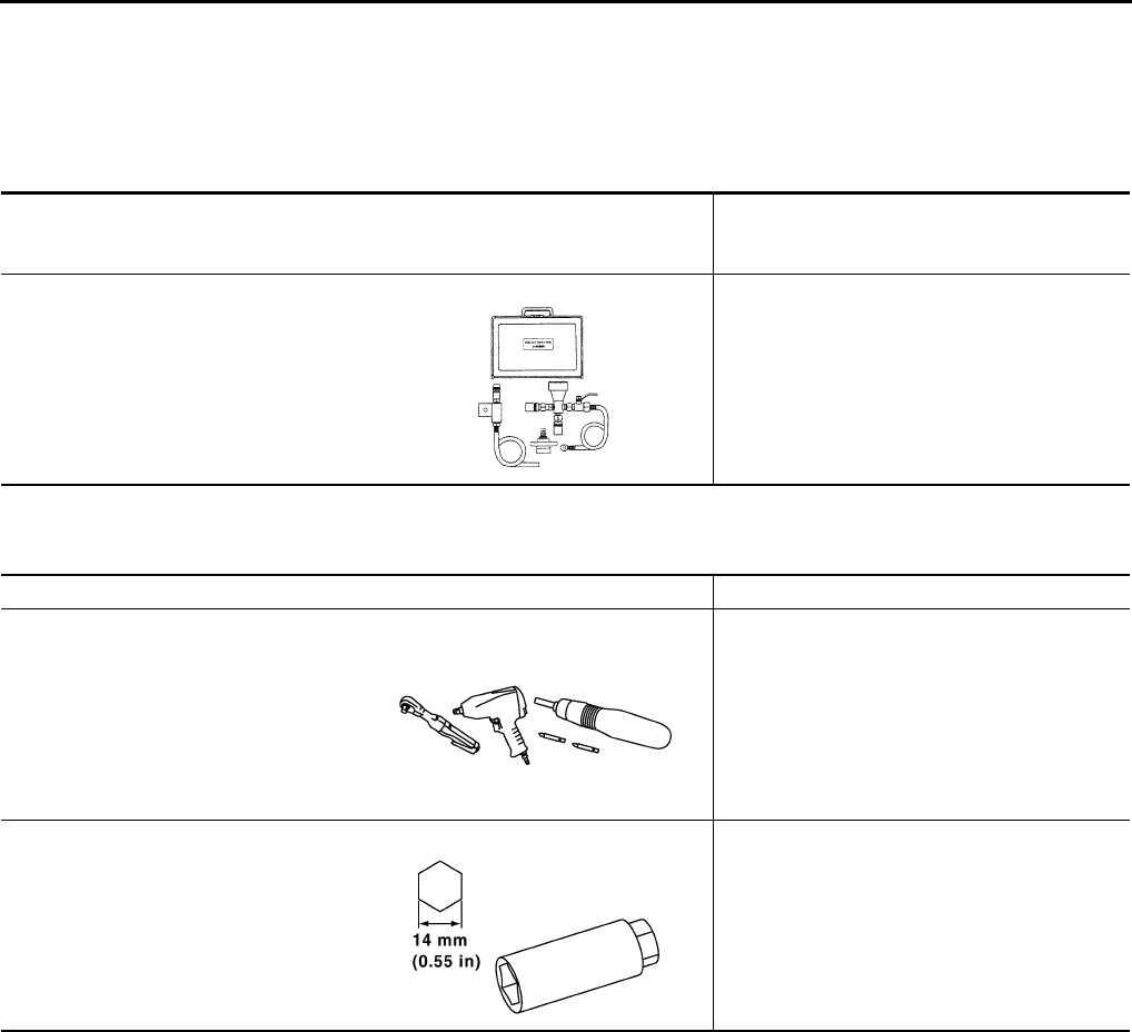
KV991J0070
(J-45695)
Coolant Refill Tool
Refilling engine cooling system
LMA053
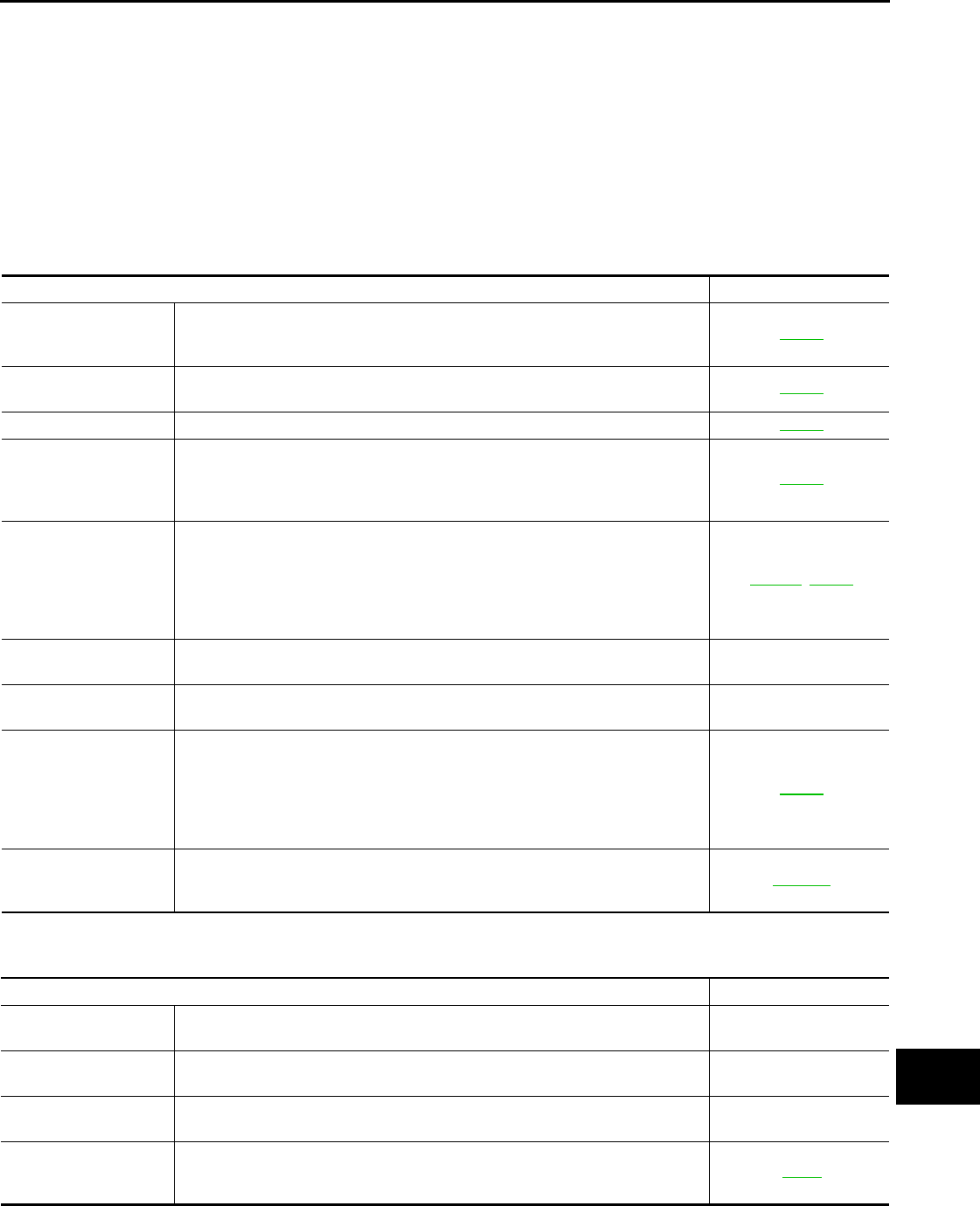
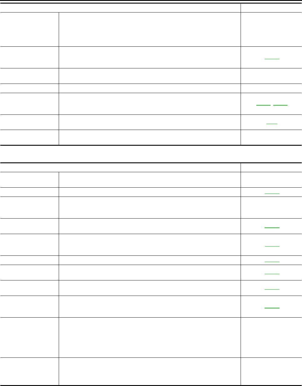
Tool name Description
Power tool Loosening nuts, screws and bolts
Spark plug wrench Removing and installing spark plug
PIIB1407E
PBIC2982E
Revision: August 2014 2015 QX60 NAM
GENERAL MAINTENANCE
MA-5
< PERIODIC MAINTENANCE >
C
D
E
F
G
H
I
J
K
L
M
B
MA
N
O
A
PERIODIC MAINTENANCE
GENERAL MAINTENANCE
FOR USA AND CANADA
FOR USA AND CANADA : Explanation of General Maintenance INFOID:0000000011131983
General maintenance includes those items which should be checked during the normal day-to-day operation
of the vehicle. They are essential if the vehicle is to continue operating properly. The owners can perform
checks and inspections themselves or have their INFINITI retailers do them.
OUTSIDE THE VEHICLE
The maintenance items listed here should be performed from time to time, unless otherwise specified.
INSIDE THE VEHICLE
The maintenance items listed here should be checked on a regular basis, such as when performing periodic maintenance, cleaning the vehicle,
etc.
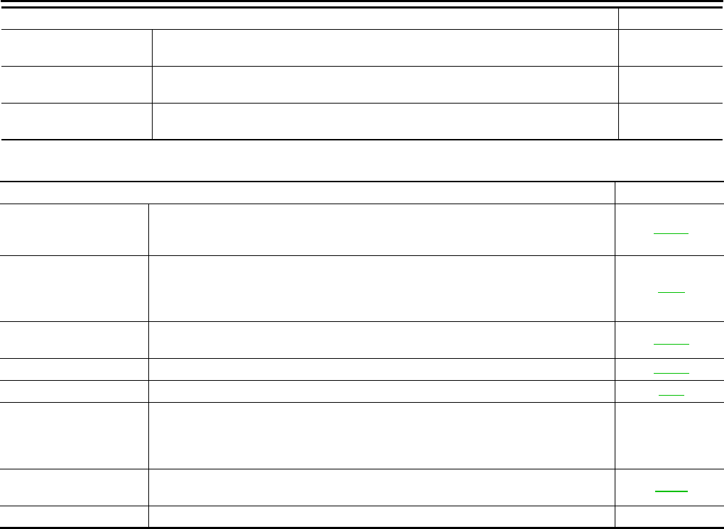
Item Reference page
Tires Check the pressure with a gauge often and always prior to long distance trips.
Adjust the pressure in all tires, including the spare, to the pressure specified.
Check carefully for damage, cuts or excessive wear.
MA-36
Wheel nuts When checking the tires, make sure no nuts are missing, and check for any loose
nuts. Tighten if necessary. MA-36
Tire rotation Tires should be rotated every 5,000 miles (8,000 km). MA-36
Tire pressure monitor-
ing system (TPMS)
transmitter compo-
nents
Replace the TPMS transmitter grommet seal, valve core and cap when the tires
are replaced due to wear or age. MA-36
Wheel alignment and
balance
If the vehicle should pull to either side while driving on a straight and level road
or if you detect uneven or abnormal tire wear, there may be a need for wheel
alignment. If the steering wheel or seat vibrates at normal highway speeds,
wheel balancing may be needed. For additional information regarding tires, refer
to “Important Tire Safety Information” (US) or “Tire Safety Information” (Canada)
in the INFINITI Warranty Information Booklet.
FSU-22, WT-52
Windshield Clean the windshield on a regular basis. Check the windshield at least every six
months for cracks or other damage. Repair as necessary. —
Windshield wiper
blades
Check for cracks or wear if they do not wipe properly. —
Doors and engine
hood
Check that all doors and the engine hood operate smoothly as well as the back
door, trunk lid and glass hatch. Also make sure that all latches lock securely. Lu-
bricate if necessary. Make sure that the secondary latch keeps the hood from
opening when the primary latch is released.
When driving in areas using road salt or other corrosive materials, check for lu-
brication frequently.
MA-43
Lamps Make sure that the headlamps, stop lamps, tail lamps, turn signal lamps and oth-
er lamps are all operating properly and installed securely. Also check headlamp
aim. Clean the headlamps on a regular basis.
EXL-162
Item Reference page
Warning lamps and
chimes
Make sure that all warning lamps and chimes are operating properly. —
Windshield wiper and
washer
Check that the wipers and washer operate properly and that the wipers do not
streak. —
Windshield defroster Check that the air comes out of the defroster outlets properly and in sufficient
quantity when operating the heater or air conditioner. —
Steering wheel Check that it has the specified play. Check for changes in the steering condition,
such as excessive play, hard steering or strange noises.
Free play: Less than 35 mm (1.38 in)
ST-47
Revision: August 2014 2015 QX60 NAM
MA-6
< PERIODIC MAINTENANCE >
GENERAL MAINTENANCE
UNDER THE HOOD AND VEHICLE
The maintenance items listed here should be checked periodically (e.g., each time you check the engine oil or refuel).
FOR MEXICO
Seats Check seat position controls such as seat adjusters, seatback recliner, etc. to
make sure they operate smoothly and that all latches lock securely in every po-
sition. Check that the head restraints move up and down smoothly and that the
locks (if equipped) hold securely in all latched positions. Check that the latches
lock securely for folding-down rear seatbacks.
—
Seat belts Check that all parts of the seat belt system (e.g., buckles, anchors, adjusters and
retractors) operate properly and smoothly and are installed securely. Check the
belt webbing for cuts, fraying, wear or damage.
MA-43
Accelerator pedal Check the pedal for smooth operation and make sure the pedal does not catch
or require uneven effort. Keep the floor mats away from the pedal. —
Brakes Check that the brake does not pull the vehicle to one side when applied. —
Brake pedal and
booster
Check the pedal for smooth operation and make sure it has the proper distance
under it when depressed fully. Check the brake booster function. Be sure to keep
the floor mats away from the pedal.
BR-20, BR-31
Parking brake Check that the lever or pedal has the proper travel and make sure that the vehicle
is held securely on a fairly steep hill when only the parking brake is applied. PB-7
CVT P (Park) position
mechanism
On a fairly steep hill check that the vehicle is held securely with the shift selector
in the P (Park) position without applying any brakes. —
Item Reference page
Item Reference page
Windshield washer
fluid
Check that there is adequate fluid in the tank. —
Engine coolant level Check the coolant level when the engine is cold. CO-10
Radiator and hoses Check the front of the radiator and clean off any dirt, insects, leaves, etc., that
may have accumulated. Make sure the hoses have no cracks, deformation, de-
terioration or loose connections.
—
Brake fluid level Make sure that the brake fluid level is between the MAX and MIN lines on the res-
ervoir. MA-38
Battery Check the fluid level in each cell. It should be between the MAX and MIN lines.
Vehicles operated in high temperatures or under severe conditions require fre-
quent checks of the battery fluid level.
PG-99
Engine drive belts Make sure that no belt is frayed, worn, cracked or oily. MA-19
Engine oil level Check the level on the oil level gauge after parking the vehicle on a level spot and
turning off the engine. MA-25
Power steering fluid
level and lines
Check the level on the dipstick with the engine off. Check the lines for improper
attachment, leaks, cracks, etc. MA-41
Exhaust system Make sure there are no loose supports, cracks or holes. If the sound of the ex-
haust seems unusual or there is a smell of exhaust fumes, immediately locate the
trouble and correct it.
MA-30
Underbody The underbody is frequently exposed to corrosive substances such as those
used on icy roads or to control dust. It is very important to remove these sub-
stances, otherwise rust will form on the floor pan, frame, fuel lines and around the
exhaust system. At the end of winter, the underbody should be thoroughly
flushed with plain water, being careful to clean those areas where mud and dirt
can easily accumulate.
—
Fluid leaks Check under the vehicle for fuel, oil, water or other fluid leaks after the vehicle
has been parked for a while. Water dripping from the air conditioner after use is
normal. If you should notice any leaks or gasoline fumes are evident, check for
the cause and correct it immediately.
—
Revision: August 2014 2015 QX60 NAM
GENERAL MAINTENANCE
MA-7
< PERIODIC MAINTENANCE >
C
D
E
F
G
H
I
J
K
L
M
B
MA
N
O
A
FOR MEXICO : General Maintenance INFOID:0000000011131984
General maintenance includes those items which should be checked during the normal day-to-day operation
of the vehicle. They are essential if the vehicle is to continue operating properly. The owners can perform the
checks and inspections themselves or they can have their INFINITI dealers do them.
OUTSIDE THE VEHICLE
The maintenance items listed here should be performed from time to time, unless otherwise specified.
INSIDE THE VEHICLE
The maintenance items listed here should be checked on a regular basis, such as when performing periodic maintenance, cleaning the vehicle,
etc.
Item Reference page
Doors and hood Check that all doors and the hood operate smoothly as well as the back door, trunk lid
and hatch. Also make sure that all latches lock securely. Lubricate if necessary. Make
sure that the secondary latch keeps the hood from opening when the primary latch is
released. When driving in areas using road salt or other corrosive materials, check lu-
brication frequently.
MA-43
Lamps Clean the headlamps on a regular basis. Make sure that the headlamps, stop lamps,
tail lamps, turn signal lamps, and other lamps are all operating properly installed se-
curely. Also check the aim of the headlamps.
—
Tires Check the pressure with a gauge often and always prior to long distance trips. Adjust
the pressure in all tires, including the spare, to the pressure specified. Check carefully
for damage, cuts or excessive wear.
WT-61
Tire rotation In the case that Two-Wheel Drive (2WD) and front & rear tires are same size; Tires
should be rotated every 10,000 km (6,000 miles). Tires marked with directional indica-
tors can only be rotated between front and rear. Make sure that the directional indica-
tors point in the direction of wheel rotation after the tire rotation is completed.
In the case that Four-Wheel Drive (4WD) and front & rear tires are same size; Tires
should be rotated every 5,000 km (3,000 miles). Tires marked with directional indica-
tors can only be rotated between front and rear. Make sure that the directional indica-
tors point in the direction of wheel rotation after the tire rotation is completed.
In the case that front tires are different size from rear tires; Tires cannot be rotated.
However, the timing for tire rotation may vary according to your driving habits and the
road surface conditions.
WT-53
Tire Pressure Monitor-
ing System (TPMS)
transmitter components
Replace the TPMS transmitter grommet seal, valve core and cap when the tires are
replaced due to wear or age. WT-56
Wheel alignment and
balance
If the vehicle should pull to either side while driving on a straight and level road, or if
you detect uneven or abnormal tire wear, there may be a need for wheel alignment. If
the steering wheel or seat vibrates at normal highway speeds, wheel balancing may
be needed.
FSU-5
Windshield Clean the windshield on a regular basis. Check the windshield at least every six
months for cracks or other damage. Repair as necessary. —
Wiper blades Check for cracks or wear if not functioning correctly. Repair as necessary. —
Item Reference page
Accelerator pedal Check the pedal for smooth operation and make sure that the pedal does not catch or
require uneven effort. Keep the floor mats away from the pedal. —
Brake pedal Check the pedal for smooth operation and make sure that it is the proper distance from
the floor mat when depressed fully. Check the brake booster function. Be sure to keep
the floor mats away from the pedal.
BR-7
Parking brake Check the parking brake operation regularly. Check that the lever (if equipped) or the
pedal (if equipped) has the proper travel. Also make sure that the vehicle is held se-
curely on a fairly steep hill when only the parking brake is applied.
PB-4
Seat belts Check that all parts of the seat belt system (for example, buckles, anchors, adjusters
and retractors) operate properly and smoothly, and are installed securely. Check the
belt webbing for cuts, fraying, wear or damage.
MA-43
Steering wheel Check for changes in the steering condition, such as excessive play, hard steering or
strange noises. Check that it has the specified play.
Free play: Less than 35 mm (1.38 in)
—
Revision: August 2014 2015 QX60 NAM
MA-8
< PERIODIC MAINTENANCE >
GENERAL MAINTENANCE
UNDER THE HOOD AND VEHICLE
The maintenance items listed here should be checked periodically (for example, each time you check the engine oil or refuel.)
Warning lamps and
chimes Make sure that all warning lamps and chimes are operating properly. —
Windshield defogger Check that the air comes out of the defogger outlets properly and in good quantity when
operating the heater or air conditioner. —
Windshield wiper and
washer Check that the wipers and washer operate properly and that the wipers do not streak. —
Item Reference page
Item Reference page
Battery Except for maintenance free battery; Check the fluid level in each cell. It should be be-
tween the “UPPER” and “LOWER” lines. Vehicles operated in high temperatures or un-
der severe conditions require frequent checks of the battery fluid level.
PG-90
Brake (and clutch) fluid
level(s)
For Manual Transmission (MT) model; Make sure that the brake and clutch fluid levels
are between the "MAX" and "MIN" lines on the reservoir(s).
Except for Manual Transmission (MT) model; Make sure that the brake fluid level is be-
tween the "MAX" and "MIN" lines on the reservoir.
BR-8
Coolant level Check the coolant level when the coolant is cold. Make sure that the coolant level is
between the “MAX” and “MIN” lines on the reservoir. CO-10
Engine drive belt(s) Make sure that drive belt(s) is/are not frayed, worn, cracked or oily. EM-12
Engine oil level Check the level after parking the vehicle (on a level ground) and turning off the engine. LU-8
Fluid leaks Check under the vehicle for fuel, oil, water or other fluid leaks after the vehicle has been
parked for a while. Water dripping from the air conditioner after use is normal. If you
should notice any leaks or if fuel fumes are evident, check for cause and have it cor-
rected immediately.
—
Power steering fluid
level and lines
Check the level when the fluid is cold, with the engine off. Check the lines for proper
attachment, leaks, cracks, etc. ST-21
Windshield washer fluid Check that there is adequate fluid in the reservoir. —
Revision: August 2014 2015 QX60 NAM
PERIODIC MAINTENANCE
MA-9
< PERIODIC MAINTENANCE >
C
D
E
F
G
H
I
J
K
L
M
B
MA
N
O
A
PERIODIC MAINTENANCE
FOR USA AND CANADA
FOR USA AND CANADA : Introduction of Periodic Maintenance INFOID:0000000011131985
The following tables show the normal maintenance schedule. Depending upon weather and atmospheric con-
ditions, varying road surfaces, individual driving habits and vehicle usage, additional or more frequent mainte-
nance may be required.
Periodic maintenance beyond the last period shown on the tables requires similar maintenance.
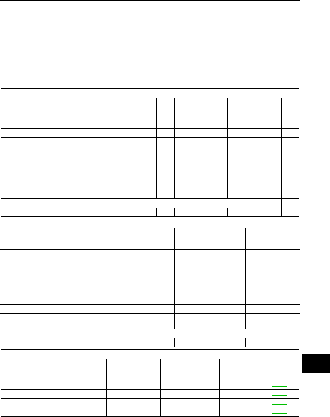
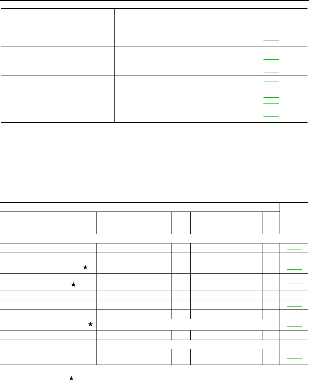
ENGINE AND EMISSION CONTROL MAINTENANCE
Abbreviations: R = Replace, I = Inspect and correct or replace as necessary
MAINTENANCE OPERATION MAINTENANCE INTERVAL
Perform either at number of miles, kilometers
or months, whichever comes first.
Miles x 1,000
(km x 1,000)
Months
5
(8)
6
10
(16)
12
15
(24)
18
20
(32)
24
25
(40)
30
30
(48)
36
35
(56)
42
40
(64)
48
45
(72)
48
Drive belts NOTE (1) I*
Air cleaner filter NOTE (2) R
EVAP vapor lines I* I*
Fuel lines I* I*
Fuel filter NOTE (3)
Engine coolant* NOTE (4)(5)
Engine oil RRRRRRRRR
Engine oil filter (Use genuine NISSAN en-
gine oil filter or equivalent) RRRRRRRRR
Spark plugs (Iridium-tipped type) NOTE (6) Replace every 105,000 miles (168,000 km)
Intake & exhaust valve clearance* NOTE (7)
MAINTENANCE OPERATION MAINTENANCE INTERVAL
Perform either at number of miles, kilometers
or months, whichever comes first.
Miles x 1,000
(km x 1,000)
Months
50
(80)
60
55
(88)
66
60
(96)
72
65
(104)
78
70
(112)
84
75
(120)
90
80
(128)
96
85
(136)
102
90
(144)
108
Drive belts NOTE (1) I* I* I* I* I*
Air cleaner filter NOTE (2) R R
EVAP vapor lines I* I*
Fuel lines I* I*
Fuel filter NOTE (3)
Engine coolant* NOTE (4)(5)
Engine oil RRRRRRRRR
Engine oil filter (Use genuine NISSAN en-
gine oil filter or equivalent) RRRRRRRR R
Spark plugs (Iridium-tipped type) NOTE (6) Replace every 105,000 miles (168,000 km)
Intake & exhaust valve clearance* NOTE (7)
MAINTENANCE OPERATION MAINTENANCE INTERVAL
Reference Page
Perform either at number of miles, kilometers
or months, whichever comes first.
Miles x 1,000
(km x 1,000)
Months
95
(152)
114
100
(160)
120
105
(168)
126
110
(176)
132
115
(184)
138
120
(192)
144
Drive belts NOTE (1) I* I* I* MA-19
Air cleaner filter NOTE (2) R MA-25
EVAP vapor lines I* I* MA-29
Fuel lines I* I* MA-24
Revision: August 2014 2015 QX60 NAM
MA-10
< PERIODIC MAINTENANCE >
PERIODIC MAINTENANCE
NOTE:
• (1) After 40,000 miles (64,000 km) or 48 months, inspect every 10,000 miles (16,000 km) or 12 months. Replace the drive belts if
found damaged.
• (2) If operating mainly in dusty conditions, more frequent maintenance may be required.
• (3) Maintenance-free item. For service procedures, refer to FL section.
• (4) First replacement interval is 105,000 miles (168,000 km) or 84 months. After first replacement, replace every 75,000 miles
(120,000 km) or 60 months.
• (5) Use only Genuine NISSAN Long Life Antifreeze / Coolant (blue) or equivalent with proper mixture ratio of 50% antifreeze and 50%
demineralized or distilled water. Mixing any other type of coolant or the use of non-distilled water will reduce the life expectancy of the
factory-fill coolant.
• (6) Replace spark plug when the spark plug gap exceeds 1.4 mm (0.055 in), even if within specified periodic replacement mileage.
• (7) Periodic maintenance is not required. However, if valve noise increases, inspect valve clearance.
*: Maintenance items and intervals with “*” are recommended by INFINITI for reliable vehicle operation. The owner need not perform
such maintenance in order to maintain the emission warranty or manufacturer recall liability. Other maintenance items and intervals are
required.
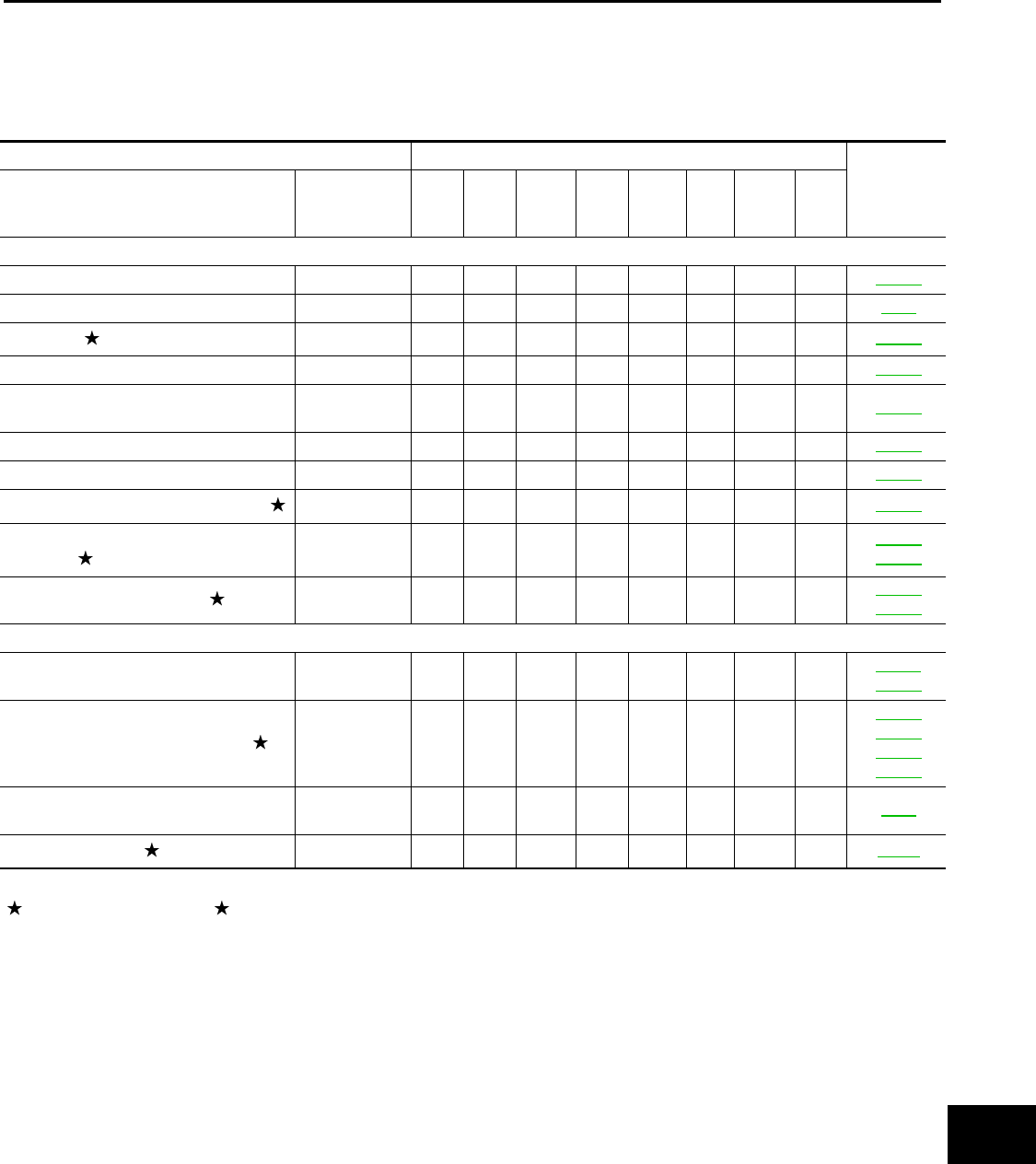
CHASSIS AND BODY MAINTENANCE
Abbreviations: R= Replace. I = Inspect. Correct or replace if necessary.
Fuel filter NOTE (3) —
Engine coolant* NOTE (4)(5) MA-19
Engine oil RRRRRR MA-25
Engine oil filter (Use genuine NISSAN engine
oil filter or equivalent) RRRRRR MA-26
Spark plugs (Iridium-tipped type) NOTE (6) Replace every 105,000 miles (168,000 km) MA-28
Intake & exhaust valve clearance* NOTE (7)
MAINTENANCE OPERATION MAINTENANCE INTERVAL
Reference Page
Perform either at number of miles, kilometers
or months, whichever comes first.
Miles x 1,000
(km x 1,000)
Months
95
(152)
114
100
(160)
120
105
(168)
126
110
(176)
132
115
(184)
138
120
(192)
144
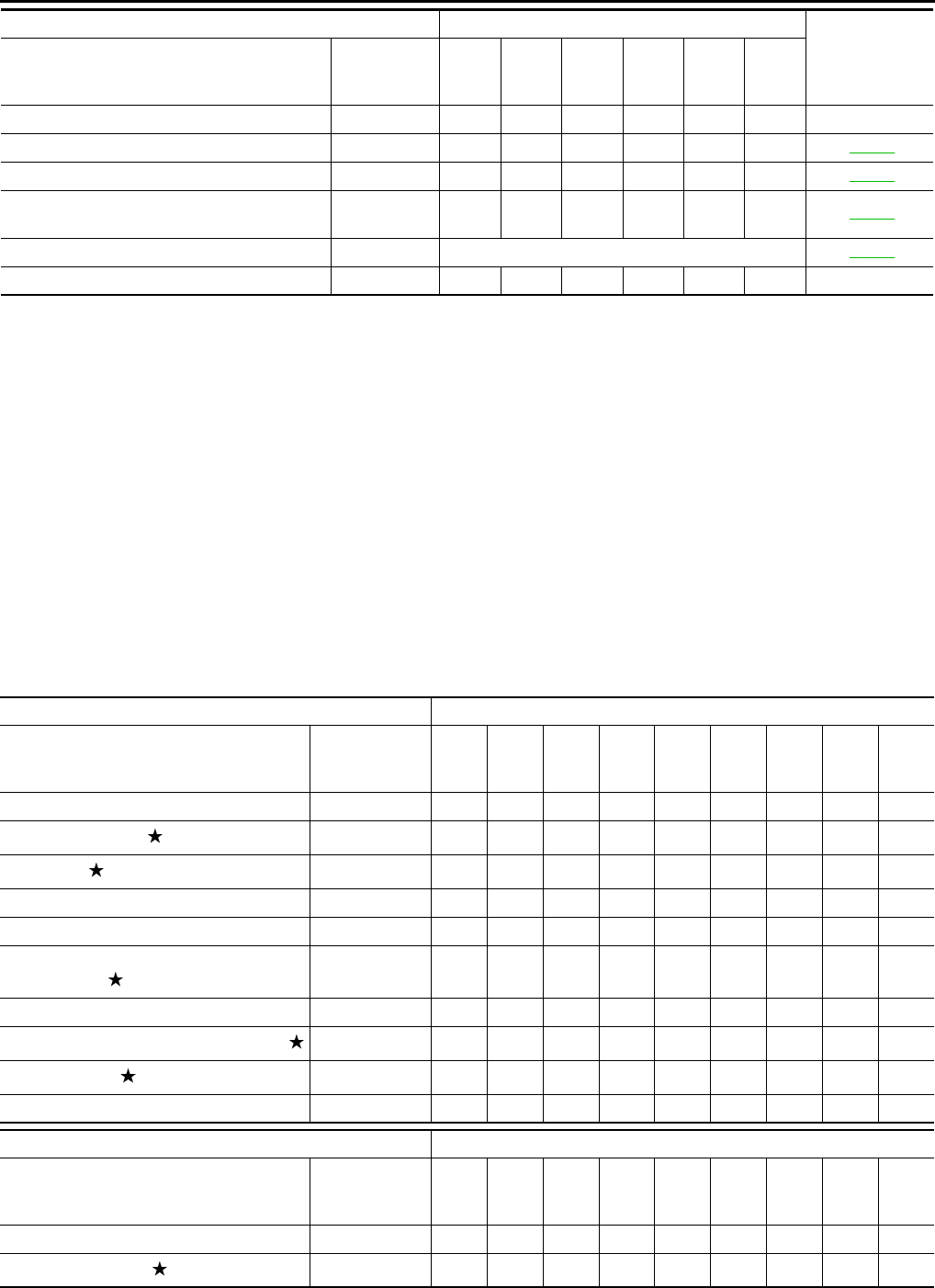
MAINTENANCE OPERATION MAINTENANCE INTERVAL
Perform either at number of miles, kilome-
ters or months, whichever comes first.
Miles x 1,000
(km x 1,000)
Months
5
(8)
6
10
(16)
12
15
(24)
18
20
(32)
24
25
(40)
30
30
(48)
36
35
(56)
42
40
(64)
48
45
(72)
54
Brake line & cables I I I I
Brake pads & rotors IIII
Brake fluid RR
CVT fluid NOTE (1) I I I I
Transfer oil & differential gear oil NOTE (2) I I I I
Steering gear and linkage, axle and sus-
pension parts II
Tire rotation NOTE (3)
Propeller shaft (AWD) & drive shaft boots IIII
Exhaust system II
In-cabin microfilter R R R
MAINTENANCE OPERATION MAINTENANCE INTERVAL
Perform either at number of miles, kilome-
ters or months, whichever comes first.
Miles x 1,000
(km x 1,000)
Months
50
(80)
60
55
(88)
66
60
(96)
72
65
(104)
78
70
(112)
84
75
(120)
90
80
(128)
96
85
(136)
102
90
(144)
108
Brake line & cables I I I I I
Brake pads & rotors IIIII
Revision: August 2014 2015 QX60 NAM
PERIODIC MAINTENANCE
MA-11
< PERIODIC MAINTENANCE >
C
D
E
F
G
H
I
J
K
L
M
B
MA
N
O
A
NOTE:
•Maintenance items with “ ” should be performed more frequently according to “Maintenance Under Severe Driving Condi-
tions”.
• (1) Use only Genuine NISSAN CVT fluid. If towing a trailer, using a camper or a car-top carrier, of driving on rough or muddy roads,
inspect CVT fluid deterioration at an INFINITI retailer every 60,000 miles (96,000 km), then change CVT fluid if necessary. And if the
inspection is not performed, change (not just inspect) CVT fluid every 60,000 miles (96,000 km).
• (2) If tower a trailer, using a camper or car-top carrier, or driving on rough or muddy roads, change (not just inspect) oil at every 20,000
miles (32,000 km) or 24 months.
• (3) Refer to "Tire rotation" under "GENERAL MAINTENANCE" heading earlier in this section.
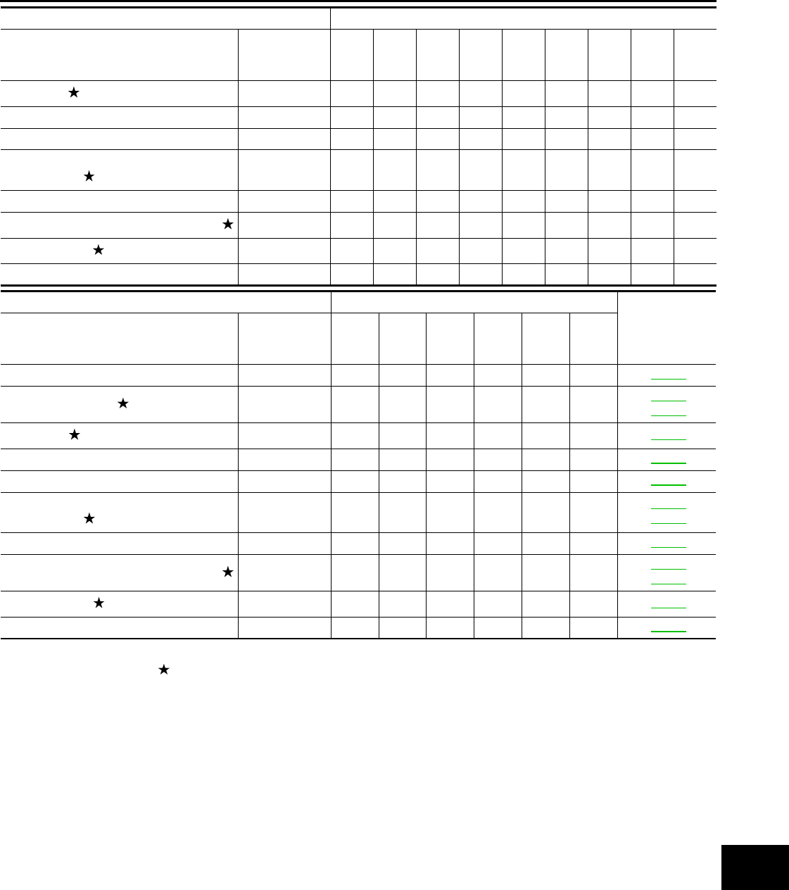
MAINTENANCE UNDER SEVERE DRIVING CONDITIONS
The maintenance intervals shown on the preceding pages are for normal operating conditions. If the vehicle is
mainly operated under severe driving conditions as shown below, more frequent maintenance must be per-
formed on the following items as shown in the table.
Severe driving conditions
• Repeated short trips of less than 5 miles (8 km).
• Repeated short trips of less than 10 miles (16 km) with outside temperatures remaining below freezing.
• Operating in hot weather in stop-and-go "rush hour" traffic.
• Extensive idling and/or low speed driving for long distances, such as police, taxi or door-to-door delivery use.
• Driving in dusty conditions.
• Driving on rough, muddy, or salt spread roads.
• Towing a trailer, using a camper or a car-top carrier
Brake fluid RR
CVT fluid NOTE (1)IIIII
Transfer oil & differential gear oilNOTE (2)IIIII
Steering gear and linkage, axle and sus-
pension parts II
Tire rotation NOTE (3)
Propeller shaft (AWD) & drive shaft boots IIIII
Exhaust system II
In-cabin microfilter R R R
MAINTENANCE OPERATION MAINTENANCE INTERVAL
Reference Page
Perform either at number of miles, kilome-
ters or months, whichever comes first.
Miles x 1,000
(km x 1,000)
Months
95
(152)
114
100
(160)
120
105
(168)
126
110
(176)
132
115
(184)
138
120
(192)
90
Brake line & cables I I I MA-38
Brake pads & rotors III
MA-40
MA-40
Brake fluid RRMA-39
CVT fluid NOTE (1) I I I MA-31
Transfer oil & differential gear oil NOTE (2) I I I MA-33
Steering gear and linkage, axle and sus-
pension parts II
MA-41
MA-42
Tire rotation NOTE (3) MA-36
Propeller shaft (AWD) & drive shaft boots III
MA-43
MA-35
Exhaust system IIMA-30
In-cabin microfilter R R MA-30
MAINTENANCE OPERATION MAINTENANCE INTERVAL
Perform either at number of miles, kilome-
ters or months, whichever comes first.
Miles x 1,000
(km x 1,000)
Months
50
(80)
60
55
(88)
66
60
(96)
72
65
(104)
78
70
(112)
84
75
(120)
90
80
(128)
96
85
(136)
102
90
(144)
108
Revision: August 2014 2015 QX60 NAM
MA-12
< PERIODIC MAINTENANCE >
PERIODIC MAINTENANCE
Maintenance operation: Check = Check and correct or replace as necessary.
FOR MEXICO
FOR MEXICO : Introduction of Periodic Maintenance INFOID:0000000011131986
The following tables show the normal maintenance schedule. Depending upon weather and atmospheric con-
ditions, varying road surfaces, individual driving habits and vehicle usage, additional or more frequent mainte-
nance may be required.
Periodic maintenance beyond the last period shown on the tables requires similar maintenance.
ENGINE AND EMISSION CONTROL MAINTENANCE
Abbreviations: I = Inspect and correct or replace as necessary, R = Replace, E = Check and correct the engine coolant mixture ratio
NOTE:
• Maintenance items with “ ” should be performed more frequently according to “Maintenance Under Severe Driving Condi-
tions”.
(1) Periodic maintenance is not required. However, if valve noise increases, check valve clearance.
(2) Replace the drive belts if found damaged or if the auto belt tensioner reading reaches the maximum limit.
(3) Use Genuine NISSAN Engine Coolant (blue) or equivalent in its quality, in order to avoid possible aluminium corrosion within the
engine cooling system caused by the use of non-genuine engine coolant. Check and correct the engine coolant mixture ratio every
48,000 km (30,000 miles) or 24 months. First replacement interval is 168,000 km (105,000 miles) or 96 months. After first replacement,
replace every 84,000 km (52,500 miles) or 48 months.
Maintenance item Maintenance
operation Maintenance interval Reference page
Brake fluid Replace Every 10,000 miles (16,000 km)
or 12 months MA-39
Brake pads & rotors Inspect Every 5,000 miles (8,000 km) or
6 months
MA-40
MA-40
MA-40
MA-40
Steering gear & linkage, axle & suspension parts Inspect Every 5,000 miles (8,000 km) or
6 months
MA-41
MA-42
Propeller shaft (AWD) & drive shaft boots Inspect Every 5,000 miles (8,000 km) or
6 months
MA-35
MA-43
Exhaust system Inspect Every 5,000 miles (8,000 km) or
6 months MA-30
MAINTENANCE OPERATION MAINTENANCE INTERVAL
Refer-
ence page
Perform either at number of kilometers
(miles) or months, whichever comes
first.
km x 1,000
(Miles x 1,000)
Months
12
(7.5)
6
24
(15)
12
36
(22.5)
18
48
(30)
24
60
(37.5)
30
72
(45)
36
84
(52.5)
42
96
(60)
48
Engine compartment and under vehicle
Intake & exhaust valve clearance See NOTE (1) EM-18
Drive belts See NOTE (2) I I MA-19
Engine oil (Use recommended oil.) RRRRRRRRMA-25
Engine oil filter (Use Genuine NISSAN
engine oil filter or equivalent.) RRRRRRRRMA-26
Engine coolant See NOTE (3) E E MA-19
Cooling system I I MA-19
Fuel lines IIMA-24
Air cleaner filter (Viscous paper type) Replace every 36,000 km (22,500 miles) or 24 months MA-25
Fuel filter (In-tank type) See NOTE (4) —
Spark plugs (Iridium-tipped type) See NOTE (5) Replace every 96,000 km (60,000 miles) MA-28
EVAP vapor lines
(With carbon canister) IIMA-29
Revision: August 2014 2015 QX60 NAM
PERIODIC MAINTENANCE
MA-13
< PERIODIC MAINTENANCE >
C
D
E
F
G
H
I
J
K
L
M
B
MA
N
O
A
(4) Fuel filter is maintenance-free. For service procedures, refer to FL section.
(5) Replace spark plug when the plug gap exceeds 1.25 mm (0.049 in) even within specified periodic replacement mileage.
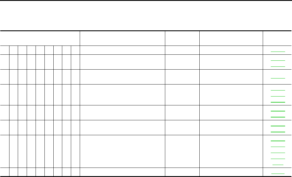
CHASSIS AND BODY MAINTENANCE
Abbreviations: I = Inspect and correct or replace as necessary, R = Replace, L=Lubricate
NOTE:
Maintenance items with “ ” should be performed more frequently according to “Maintenance Under Severe Driving Condi-
tions”.
• (1) Use only Genuine NISSAN CVT fluid. If towing a trailer, using a camper or a car-top carrier or driving on a rough or muddy roads,
inspect CVT fluid deterioration at INFINITI dealers every 96,000 km (60,000 miles), then change CVT fluid if necessary. And if the
inspection is not performed, change (not just inspect) CVT fluid every 96,000 km (60,000 miles).
MAINTENANCE UNDER SEVERE DRIVING CONDITIONS
The maintenance intervals shown on the preceding pages are for normal operating conditions. If the vehicle is
mainly operated under severe driving conditions as shown below, more frequent maintenance must be per-
formed on the following items as shown in the table.
Severe driving conditions
A — Driving under dusty conditions
B — Driving repeatedly short distances
C — Towing a trailer or caravan
D — Extensive idling
E —Driving in extremely adverse weather conditions or in areas where ambient temperatures are either
extremely low or extremely high
F — Driving in high humidity or mountainous areas
MAINTENANCE OPERATION MAINTENANCE INTERVAL
Reference
page
Perform either at number of kilometers
(miles) or months, whichever comes first.
km x 1,000
(Miles x 1,000)
Months
12
(7.5)
6
24
(15)
12
36
(22.5)
18
48
(30)
24
60
(37.5)
30
72
(45)
36
84
(52.5)
42
96
(60)
48
Underhood and under vehicle
Brake line & cables I I I I MA-39
Brake fluid (For level & leaks) I I I I BR-8
Brake fluid RRMA-39
CVT fluid (For level & leaks) NOTE (1) I I I I MA-31
Power steering fluid & lines (For level &
leaks) IIIIMA-41
Exhaust system I I MA-30
Transfer fluid (For level & leaks) I I I I MA-33
Differential gear oil (For level & leaks) IIIIMA-34
Steering gear & linkage, axle & suspen-
sion parts II
MA-41
MA-42
Propeller shaft & drive shafts IIII
MA-35
MA-43
Outside and inside
Wheel alignment (If necessary, rotate &
balance wheels) IIII
FSU-5
RSU-6
Brake pads, rotors, drums & linings IIII
MA-40
MA-40
MA-40
MA-40
Foot brake & parking brake
(For free play, stroke & operation) IIIIPB-4
Air conditioner filter RRRRVTL-6
Revision: August 2014 2015 QX60 NAM
MA-14
< PERIODIC MAINTENANCE >
PERIODIC MAINTENANCE
G — Driving in areas using salt or other corrosive areas
H — Driving on rough and/or muddy roads or in the desert
I — Driving with frequent use of braking or in mountainous areas
Maintenance operation: Inspect = Check and correct or replace as necessary.
Driving condition Maintenance item Maintenance
operation Maintenance interval Reference
page
A........Air cleaner filter (Viscous paper type)Replace More frequently MA-25
A B C D . . . . . Engine oil & engine oil filter Replace Every 6,000 km (3,750
miles) or 3 months
MA-26
MA-26
.....F...Brake fluid Replace Every 24,000 km (15,000
miles) or 12 months MA-39
..C....H.Differential gear oil Replace Every 36,000 km (22,500
miles) or 24 months
MA-34
MA-34
MA-35
......GH.
Steering gear & linkage, axle & sus-
pension parts Inspect Every 24,000 km (15,000
miles) or 12 months
MA-41
MA-42
......GH.Propeller shaft & drive shafts Inspect Every 12,000 km (7,500
miles) or 6 months
MA-35
MA-43
A . C . . . G H I Brake pads, rotors, drums & linings Inspect Every 12,000 km (7,500
miles) or 6 months
MA-40
MA-40
MA-40
MA-40
PB-4
A........Air conditioner filter Replace More frequently VTL-6
Revision: August 2014 2015 QX60 NAM
RECOMMENDED FLUIDS AND LUBRICANTS
MA-15
< PERIODIC MAINTENANCE >
C
D
E
F
G
H
I
J
K
L
M
B
MA
N
O
A
RECOMMENDED FLUIDS AND LUBRICANTS
FOR USA AND CANADA
FOR USA AND CANADA : Fluids and Lubricants INFOID:0000000011131987
The following are approximate capacities, The actual refill capacities may be slightly different.
When refilling, follow the procedures described elsewhere in this manual.
Description Capacity (Approximate) Recommended Fluids/Lubricants
Metric US measure Imp measure
Fuel 74.0 19-1/2 gal 16-1/4 gal Unleaded gasoline with an octane rating of
at least 91 AKI (RON 96)
Engine oil
Drain and refill
With oil filter
change 4.8 5-1/8 qt 4-1/4 qt Genuine NISSAN engine oil or equivalent
• Engine oil with API Certification Mark
(For further details, see “Engine Oil Rec-
ommendation”.), Viscosity SAE 0W-20
(As an alternative to this recommended oil,
SAE 5W-30 conventional petroleum based
oil may be used and meet all specifications
and requirements necessary to maintain the
New Vehicle Limited Warranty.)
Without oil fil-
ter change 4.5 4-3/4 qt 4 qt
Dry engine
(Overhaul) 5.1 5-3/8 qt 4-1/2 qt
Cooling system
(with reservoir at MAX level) 9.6 10-1/8 qt 8-1/2 qt Pre-diluted Genuine NISSAN Long Life An-
tifreeze/ Coolant (blue) or equivalent
CVT fluid 8.8 9-1/4 qt 7-3/4 qt
Genuine NISSAN CVT Fluid NS-3
(Use only Genuine NISSAN CVT Fluid
NS-3. Using transmission fluid other
than Genuine NISSAN CVT Fluid NS-3
will damage the CVT, which is not cov-
ered by the INFINITI new vehicle limited
warranty.)
Differential gear oil 0.5 1-1/8 pt 7/8 pt
Genuine NISSAN Differential Oil Hypoid
Super Semi-synthetic API GL-5, Viscosity
SAE 75W-90
(The use of differential gear oil other than
the specified may cause vehicle malfunc-
tions and result in non-warranty vehicle re-
pairs.)
Transfer fluid 0.31 5/8 pt 1/2 pt API GL-5, Viscosity SAE 80W-90 or equiva-
lent
Power steering fluid (E-PSF) 1.0 2-1/8 pt 1-3/4 pt
Genuine NISSAN E-PSF or equivalent
(Use of a power steering fluid other than
Genuine NISSAN E-PSF will prevent the
power steering system from operating prop-
erly.)
Brake fluid — — —
Genuine NISSAN Super Heavy Duty Brake
Fluid or equivalent
DOT 3 (US FMVSS No. 116)
(Available in mainland U.S.A. through an
INFINITI retailer.)
Multi-purpose grease — — — NLGI No. 2 (Lithium soap base)
Windshield washer fluid 5.0 5-1/4 qt 4-3/8 qt Genuine NISSAN Windshield Washer Con-
centrate Cleaner & Antifreeze or equivalent
Air conditioning system refrigerant 0.80 ± 0.03 kg 1.80 ± 0.07 lb 1.80 ± 0.07 lb
HFC-134a (R-134a)
(For further information, see “Air condition-
ing specification label”.)
Air conditioning system oil 230 m 7.8 fl oz 8.1 fl oz
A/C System Oil Type S (DH-PS)
(For further information, see “Air condition-
ing specification label”.)
Revision: August 2014 2015 QX60 NAM
MA-16
< PERIODIC MAINTENANCE >
RECOMMENDED FLUIDS AND LUBRICANTS
FOR USA AND CANADA : Engine Oil Recommendation INFOID:0000000011131988
INFINITI recommends the use of an energy conserving oil in order to improve fuel economy. Select only
engine oils that meet the American Petroleum Institute (API) certification and International Lubricant Standard-
ization and Approval Committee (ILSAC) certification and SAE viscosity standard. These oils have the API
certification mark on the front of the container. Oils which do not have the specified quality label should not be
used as they could cause engine damage.
FOR USA AND CANADA : Engine Coolant Mixture Ratio INFOID:0000000011131989
The engine cooling system is filled at the factory with a pre-diluted mixture of 50% Genuine NISSAN Long Life
Antifreeze/Coolant (blue) and 50% water to provide year-round anti-freeze and coolant protection. The anti-
freeze solution contains rust and corrosion inhibitors. Additional engine cooling system additives are not nec-
essary.
WARNING:
Do not remove the radiator cap when the engine is hot. Serious burns could occur from high-pressure
engine coolant escaping from the radiator. Wrap a thick cloth around the cap. Slowly push down and
turn it a quarter turn to allow built-up pressure to escape. Carefully remove the cap by pushing it down
and turning it all the way.
CAUTION:
• When adding or replacing coolant, be sure to use only Genuine NISSAN Long Life Antifreeze/Cool-
ant (blue) or equivalent. Genuine NISSAN Long Life Antifreeze/Coolant (blue) is pre-diluted to pro-
vide antifreeze protection to -34°F (-37°C). If additional freeze protection is needed due to weather
where the vehicle is operated, add Genuine NISSAN long life Antifreeze/Coolant (blue) concentrate
following the directions on the container. If an equivalent coolant other than Genuine NISSAN Long
Life Antifreeze/Coolant (blue) is used, follow the coolant manufacturer’s instructions to maintain
minimum antifreeze protection to -34°F (-37°C). The use of other types of coolant solutions other
than Genuine NISSAN Long Life Antifreeze/Coolant (blue) or equivalent may damage the engine
cooling system.
• Mixing any other type of coolant other than Genuine NISSAN Long Life Antifreeze/Coolant (blue),
including Genuine NISSAN Long Life Antifreeze/Coolant (green) or the use of non-distilled water will
reduce the life expectancy of the factory filled coolant.
FOR MEXICO
FOR MEXICO : Fluids and Lubricants INFOID:0000000011131990
The following are approximate capacities, The actual refill capacities may be slightly different.
When refilling, follow the procedures described elsewhere in this manual.
ALPIA0008ZZ
1. API certification mark 2. API service symbol
Capacity (Approximate) Recommended Fluids/Lubricants
Metric US measure Imp measure
Fuel 74.0 19-1/2 gal 16-1/4 gal Unleaded gasoline with an octane rating of
at least 91 AKI (RON 96)
Revision: August 2014 2015 QX60 NAM
RECOMMENDED FLUIDS AND LUBRICANTS
MA-17
< PERIODIC MAINTENANCE >
C
D
E
F
G
H
I
J
K
L
M
B
MA
N
O
A
Engine oil
Drain and refill
With oil filter
change 4.8 5-1/8 qt 4-1/4 qt
Nippon oil (Genuine NISSAN engine oil
API grade SM, Viscosity SAE 5W-30)
Without oil filter
change 4.5 4-3/4 qt 4 qt
Dry engine (engine
overhaul) 5.1 5-3/8 qt 4-1/2 qt
Cooling system
(with reservoir at MAX line) 9.6 10-1/8 qt 8-1/2 qt
Genuine NISSAN Engine Coolant (blue) or
equivalent
(Use Genuine NISSAN Engine Coolant or
equivalent in its quality, in order to avoid
possible aluminum corrosion within the en-
gine cooling system caused by the use of
non-genuine engine coolant.Note that any
repairs for the incidents within the engine
cooling system while using non-genuine
engine coolant may not be covered by the
warranty even if such incidents occurred
during the warranty period.)
CVT fluid 8.8 9-1/4 qt 7-3/4 qt
Genuine NISSAN CVT fluid NS-3
(Use only Genuine NISSAN CVT Fluid
NS-3. Using transmission fluid other
than Genuine NISSAN CVT Fluid NS-3
will damage the CVT, which is not cov-
ered by the INFINITI new vehicle limited
warranty.)
Differential gear oil 0.5 1-1/8 pt 7/8 pt
Genuine NISSAN Diff oil Hypoid Super
Semi-synthetic GL-5 75W-90
(Use Genuine NISSAN Diff Oil Hypoid Su-
per semi-synthetic GL-5. Using differential
gear oil other than Genuine NISSAN Diff
Oil Hypoid Super semi-synthetic will dam-
age the differential gear, which is not cov-
ered by the warranty.)
Transfer fluid 0.31 5/8 pt 1/2 pt
Genuine NISSAN Differential Oil Hypoid
Super GL-5 80W-90 or API GL-5, Viscosity
SAE 80W-90
Power steering fluid 1.0 2-1/8 pt 1-3/4 pt
Genuine NISSAN E-PSF or equivalent
(Use of a power steering fluid other than
Genuine NISSAN E-PSF will prevent the
power steering system from operating
properly.)
Brake fluid — — — Genuine NISSAN Brake Fluid or equiva-
lent DOT 3 (US FMVSS No. 116)
Multi-purpose grease — — — NLGI No. 2 (Lithium soap base)
Windshield washer fluid 5.0 5-1/4 qt 4-3/8 qt
Genuine NISSAN Windshield Washer
Concentrate Cleaner & Antifreeze or
equivalent
Air conditioning system refrigerant 0.80 ± 0.03 kg 1.80 ± 0.07 lb 1.80 ± 0.07 lb
HFC-134a (R-134a)
(For further information, see “Air condition-
ing specification label”.)
Air conditioning system oil 230 m 7.8 fl oz 8.1 fl oz
A/C System Oil Type S (DH-PS)
(For further information, see “Air condition-
ing specification label”.)
Capacity (Approximate) Recommended Fluids/Lubricants
Metric US measure Imp measure
Revision: August 2014 2015 QX60 NAM
MA-18
< PERIODIC MAINTENANCE >
RECOMMENDED FLUIDS AND LUBRICANTS
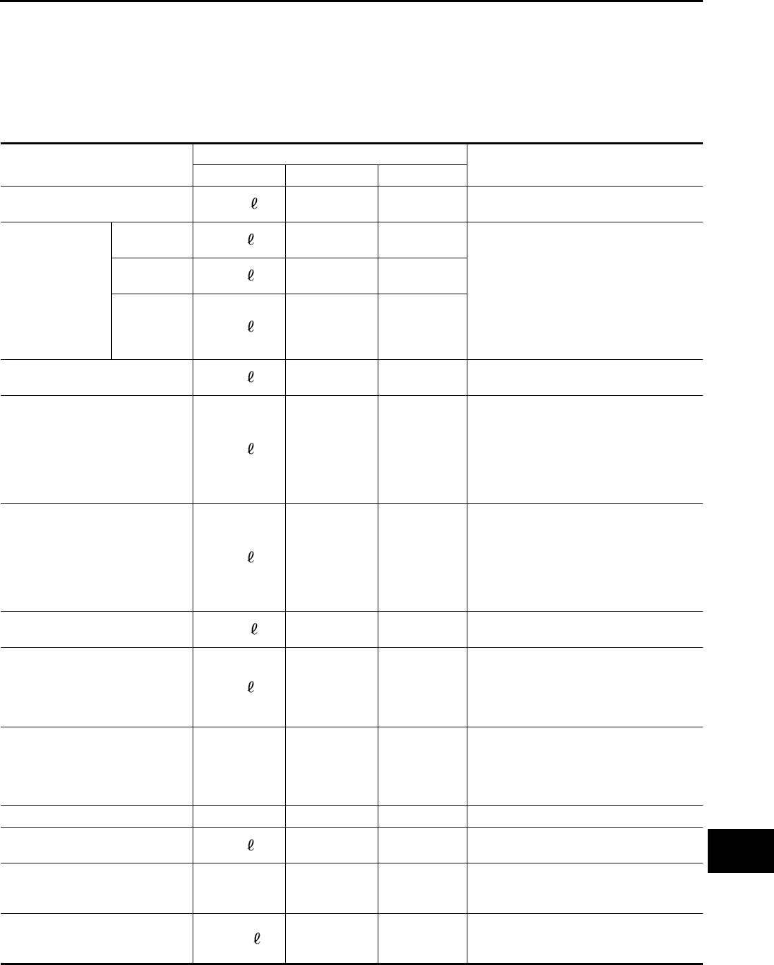
FOR MEXICO : Engine Coolant Mixture Ratio INFOID:0000000011131992
The engine cooling system is filled at the factory with a high-quality, year-round and extended life engine cool-
ant. The high quality engine coolant contains the specific solutions effective for the anti-corrosion and the anti-
freeze function. Therefore, additional cooling system additives are not necessary.
Coolant Mixture Ratios
CAUTION:
• When adding or replacing coolant, be sure to use only a Genuine NISSAN Engine Coolant or equiva-
lent in its quality with the proper mixture ratio. See the examples shown in the figure.
The use of other types of engine coolant may damage the engine cooling system.
• When checking the engine coolant mixture ratio by the coolant hydrometer, use the chart below to correct
your hydrometer reading (specific gravity) according to coolant temperature.
Mixed coolant specific gravity
Unit: specific gravity
WARNING:
Do not remove the radiator cap when the engine is hot. Serious burns could occur from high pressure
engine coolant escaping from the radiator. Wrap a thick cloth around the cap. Slowly turn it a quarter
turn to allow built-up pressure to escape. Carefully remove the cap by turning it all the way.
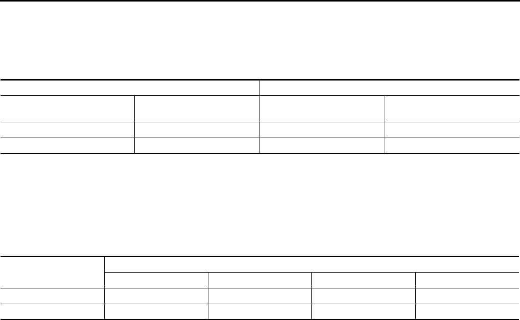
For outside temperatures down to: Anti-freeze coolant mixture ratio
° C ° F Genuine NISSAN Engine
Coolant or equivalent
Demineralized water or distilled
water
– 15°5°30 % 70 %
– 35°– 30°50 % 50 %
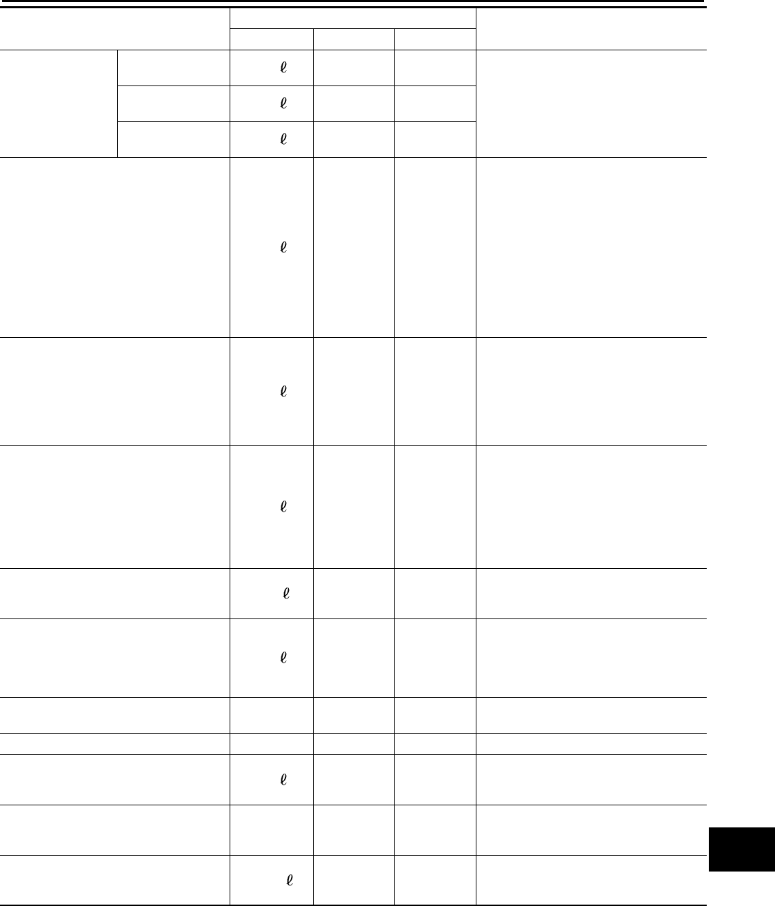
Engine coolant mixture
ratio
Coolant temperature °C (°F)
15 (59) 25 (77) 35 (95) 45 (113)
30% 1.046 - 1.050 1.042 - 1.046 1.038 - 1.042 1.033 - 1.038
50% 1.076 - 1.080 1.070 - 1.076 1.065 - 1.071 1.059 - 1.065
Revision: August 2014 2015 QX60 NAM
ENGINE MAINTENANCE (VQ35DE)
MA-19
< PERIODIC MAINTENANCE >
C
D
E
F
G
H
I
J
K
L
M
B
MA
N
O
A
ENGINE MAINTENANCE (VQ35DE)
DRIVE BELTS
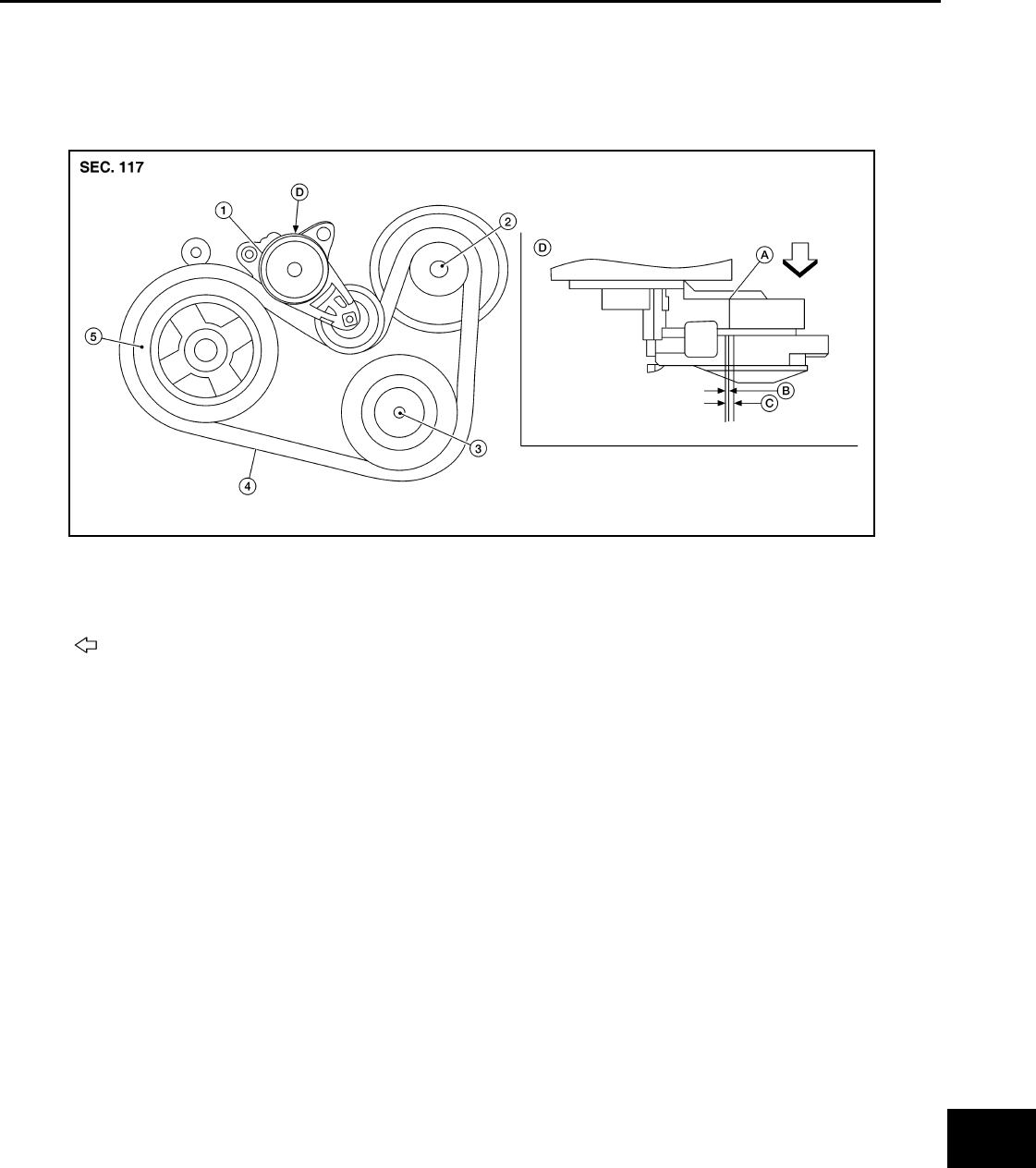
DRIVE BELTS : Checking Drive Belts INFOID:0000000011131993
WARNING:
Inspect and check the drive belt with the engine off.
1. Visually check entire drive belt for wear, damage or cracks.
2. Check that the drive belt auto-tensioner indicator is within the possible use range.
NOTE:
• When new drive belt is installed, the drive belt auto-tensioner indicator should be within the new drive
belt range.
• Check the drive belt auto-tensioner indicator when the engine is cold.
3. If the drive belt auto-tensioner indicator is out of the possible use range or belt is damaged, replace drive
belt.
DRIVE BELTS : Tension Adjustment INFOID:0000000011131994
• Drive belt tension is automatically adjusted by the drive belt auto-tensioner.
• Drive belt tension is not manually adjustable.
ENGINE COOLANT
ENGINE COOLANT : System Inspection INFOID:0000000011131995
WARNING:
Do not remove the radiator cap when the engine is hot. Serious burns could occur from high pressure
engine coolant escaping from the radiator. Wrap a thick cloth around the cap. Slowly turn it a quarter
turn to allow built-up pressure to escape. Carefully remove the cap by turning it all the way.
CHECKING COOLING SYSTEM HOSES
Check hoses for the following:
• Improper attachment
• Leaks
•Cracks
1. Drive belt auto-tensioner 2. Generator 3. A/C compressor
4. Drive belt 5. Crankshaft pulley A. Indicator
B. Range when new drive belt is installed C. Possible use range D. View D
Engine front
AWBIA1225GB
Revision: August 2014 2015 QX60 NAM
MA-20
< PERIODIC MAINTENANCE >
ENGINE MAINTENANCE (VQ35DE)
• Damage
• Loose connections
• Chafing
• Deterioration
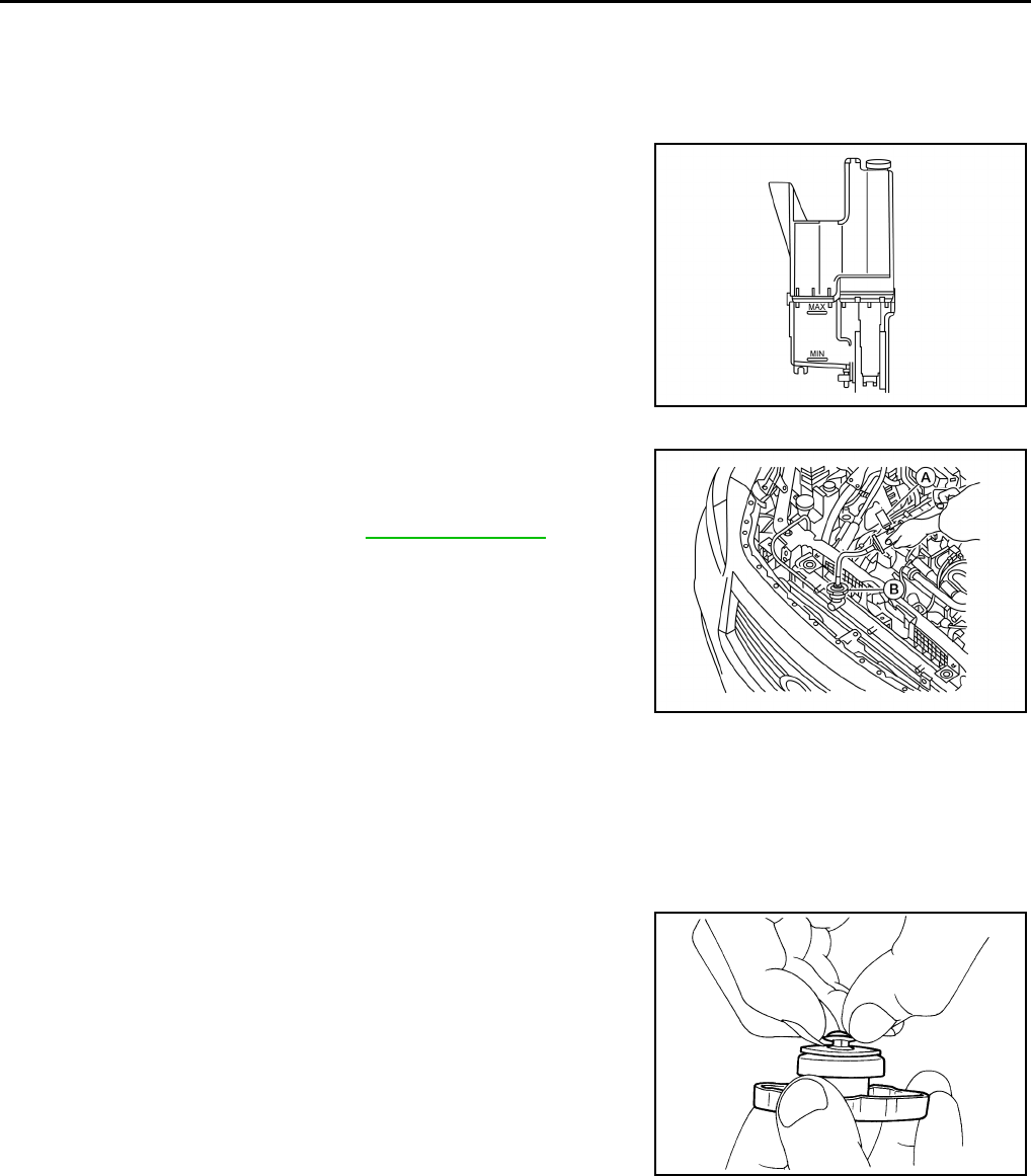
CHECKING RESERVOIR LEVEL
• Check the coolant reservoir tank level when the engine is cool.
• Adjust engine coolant level, if necessary, to ensure that the engine
coolant level is within the MIN to MAX range.
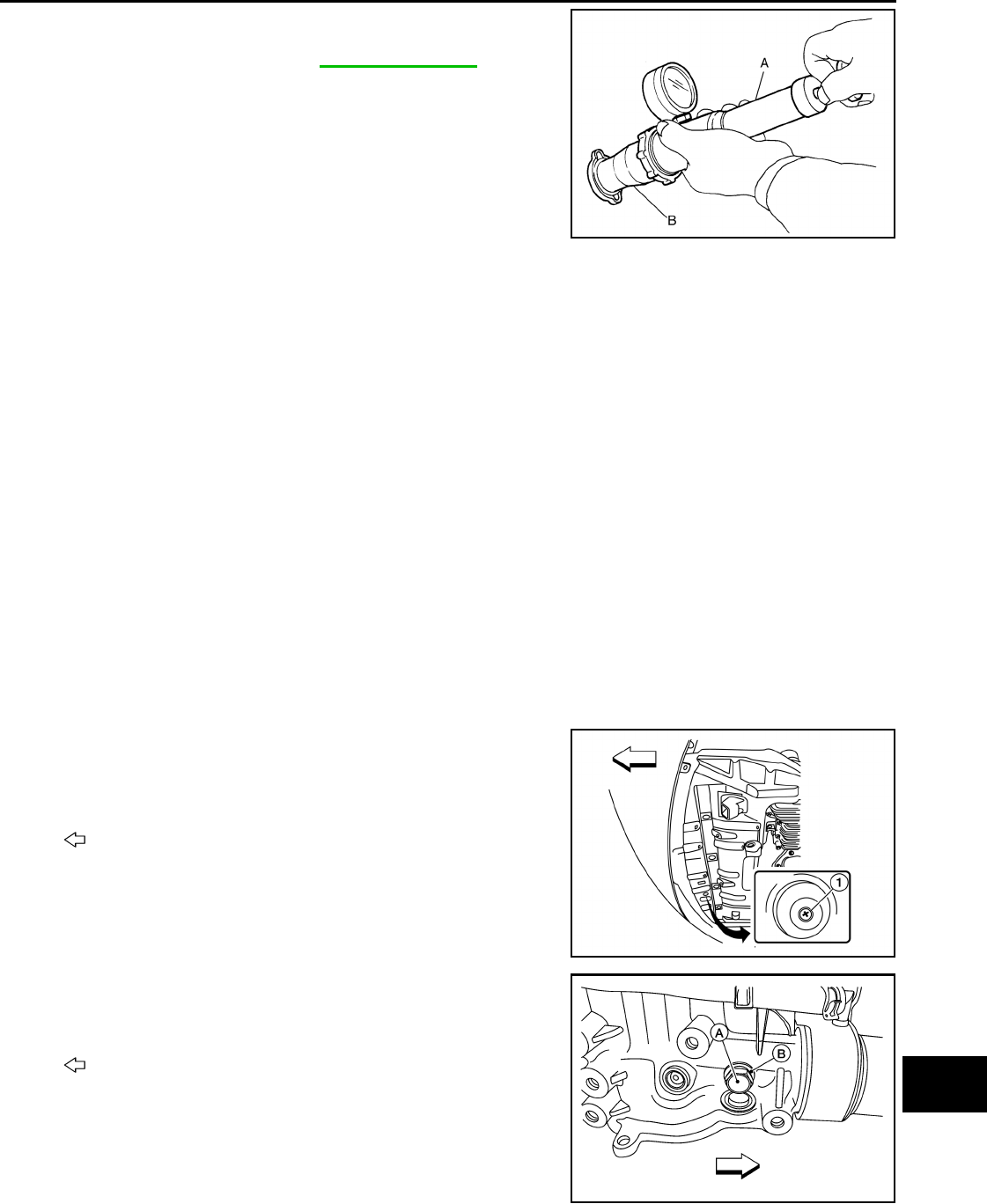
CHECKING COOLING SYSTEM FOR LEAKS
To check for leaks, apply pressure to the cooling system using suit-
able tools (A and B).
WARNING:
Do not remove the radiator cap when the engine is hot. Serious
burns could occur from high pressure engine coolant escaping
from the radiator.
CAUTION:
Higher test pressure than specified may cause radiator dam-
age.
CHECKING RADIATOR CAP
1. Inspect the radiator cap.
• Replace the cap if the metal plunger cannot be seen around the edge of the black rubber gasket.
• Replace the cap if deposits of waxy residue or other foreign material are on the black rubber gasket or
the metal retainer.
NOTE:
Thoroughly wipe out the radiator filler neck to remove any waxy residue or foreign material.
2. Pull the negative-pressure valve to open it and check that it
closes completely when released.
• Check that there is no dirt or damage on the valve seat of the
radiator cap negative-pressure valve.
• Check that there are no abnormalities in the opening and clos-
ing conditions of the negative-pressure valve.
AWBIA1183GB
Testing pressure : Refer to CO-28, "Radiator".
AWBIA1188GB
SMA967B
Revision: August 2014 2015 QX60 NAM
ENGINE MAINTENANCE (VQ35DE)
MA-21
< PERIODIC MAINTENANCE >
C
D
E
F
G
H
I
J
K
L
M
B
MA
N
O
A
3. Check radiator cap relief pressure using suitable tools (A and B).
• Apply water or engine coolant to the cap seal surface before
connecting the radiator cap to the tester,
• Replace the radiator cap if there is an abnormality in the nega-
tive-pressure valve, or if the open-valve pressure is outside of
the standard values.
CHECKING RADIATOR
Check radiator for mud or clogging. If necessary, clean radiator as follows.
CAUTION:
• Be careful not to bend or damage the radiator fins.
• When radiator is cleaned on-vehicle, remove surrounding parts in order to access the radiator core.
Tape the harness and harness connectors to prevent water from entering.
1. Spray water to the back side of the radiator core using a side to side motion from the top down.
2. Stop spraying when debris no longer flows from radiator core.
3. Blow air into the back side of radiator core using a side to side motion from the top down.
• Use compressed air lower than 490 kPa (5.00 kg/cm2, 71.1 psi) and keep distance more than 30 cm
(11.8 in).
4. Continue to blow air until no water sprays out.
5. Check for engine coolant leaks. Repair as necessary.
ENGINE COOLANT : Changing Engine Coolant INFOID:0000000011131996
WARNING:
Do not remove the radiator cap when the engine is hot. Serious burns could occur from high pressure
engine coolant escaping from the radiator. Wrap a thick cloth around the cap. Slowly turn it a quarter
turn to allow built-up pressure to escape. Carefully remove the cap by turning it all the way.
DRAINING ENGINE COOLANT
1. Open radiator drain plug (1) at the bottom of radiator and
remove the radiator filler cap.
CAUTION:
Do not allow the engine coolant to contact the drive belt.
2. Remove water drain plug (A) and copper sealing washer (B).
CAUTION:
Do not reuse copper sealing washers.
Standard : Refer to CO-28, "Radiator".
AWBIA1189GB
: Front
AWBIA1180GB
: Front
AWBIA1202GB
Revision: August 2014 2015 QX60 NAM
MA-22
< PERIODIC MAINTENANCE >
ENGINE MAINTENANCE (VQ35DE)
3. For a complete cooling system drain, remove the reservoir tank and drain the engine coolant, and then
clean the reservoir tank before installation.
CAUTION:
Do not allow the engine coolant to contact the drive belt.
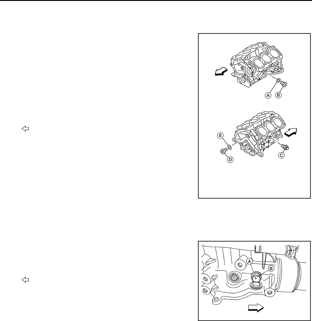
4. When performing a complete cooling system drain, remove the
water drain plug (B), connector bolt (C), and copper sealing
washer (A) on the cylinder block.
CAUTION:
Do not reuse copper sealing washers.
NOTE:
• For Canada, water drain plug (B) is a block heater, not a drain
plug.
• Remove water drain plug (D) and copper sealing washer (E)
during engine overhaul.
CAUTION:
Do not reuse copper sealing washers.
5. Check the drained engine coolant for contaminants such as rust, corrosion or discoloration.
• If contaminated, flush the engine cooling system. Refer to FLUSHING COOLING SYSTEM.
REFILLING ENGINE COOLANT
1. Install the radiator drain plug and the reservoir tank, (if removed).
2. Install the water drain plug (A) and copper sealing washer (B).
Tighten water drain plug to specification.
CAUTION:
Do not reuse copper sealing washers.
: Front
AWBIA1194GB
: Front
Water drain plug (A) : 12.25 N·m (1.2 kg-m, 9.0 ft-lb)
AWBIA1202GB
Revision: August 2014 2015 QX60 NAM
ENGINE MAINTENANCE (VQ35DE)
MA-23
< PERIODIC MAINTENANCE >
C
D
E
F
G
H
I
J
K
L
M
B
MA
N
O
A
3. Install the cylinder block drain plugs (if removed).
• Apply sealant to the thread of the water drain plug (B), connec-
tor bolt (C) and water drain plug (D), (if removed).
CAUTION:
Do not reuse copper sealing washers.
NOTE:
• For Canada, water drain plug (B) in is a block heater, not a
water drain plug.
• Install copper sealing washers (E) and (A), (if removed).
• Use Genuine High Performance Thread Sealant or equiva-
lent. Refer to GI-22, "Recommended Chemical Products and
Sealants".
• Tighten each plug and connector bolt to specifications.
4. If disconnected, reattach the upper radiator hose at the engine side.
5. Set the vehicle heater controls to the full HOT and heater ON position. Turn the vehicle ignition ON with
the engine OFF as necessary to activate the heater mode.
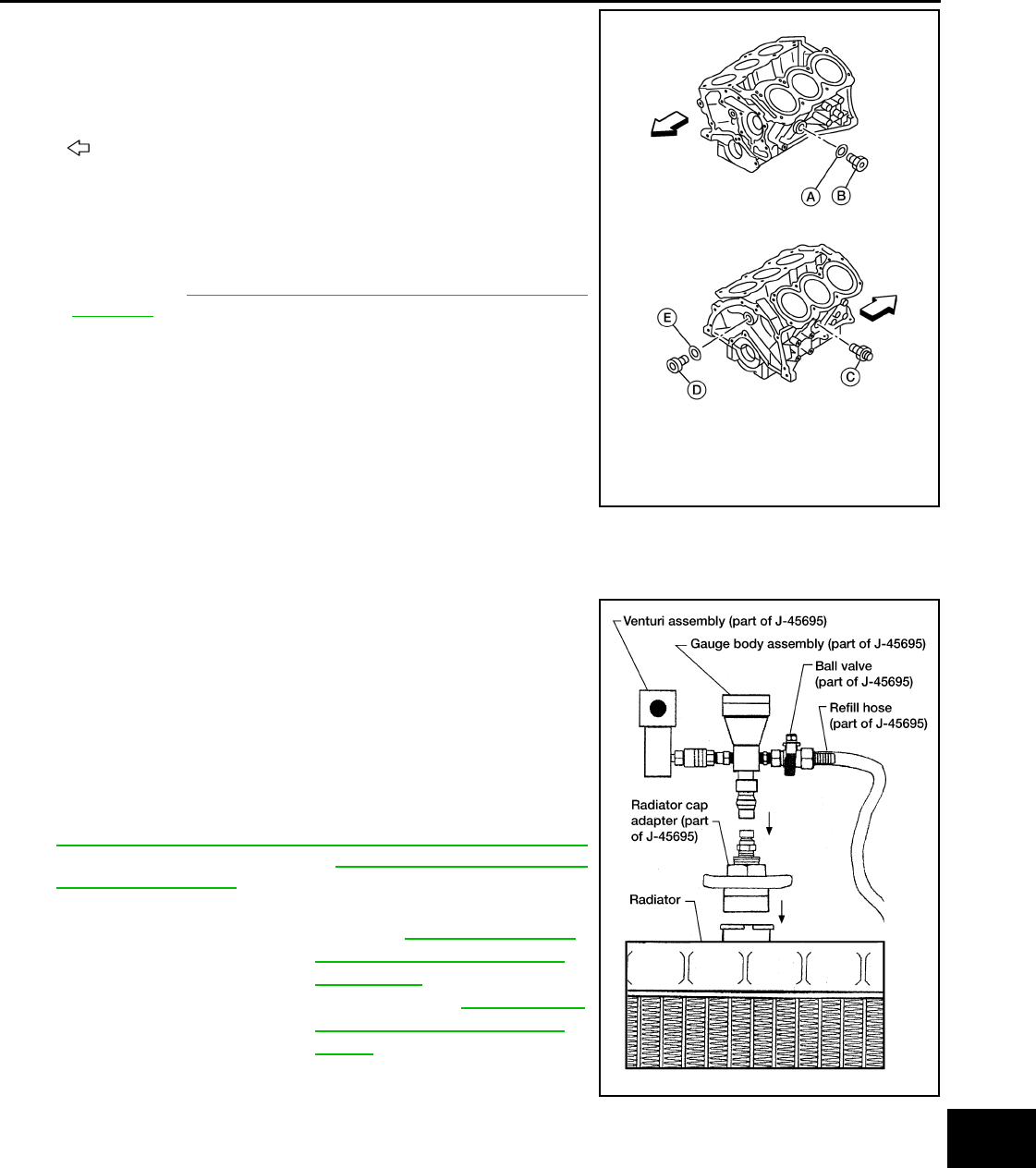
6. Install the Tool by installing the radiator cap adapter onto the
radiator neck opening. Then attach the gauge body assembly
with the refill tube and the Venturi assembly to the radiator cap
adapter.
7. Insert the refill hose into the engine coolant mixture container
that is placed at floor level. Make sure the ball valve is in the
closed position.
•Use the specified engine coolant or equivalent. Refer to
MA-15, "FOR USA AND CANADA : Fluids and Lubricants"
(United States and Canada) or MA-16, "FOR MEXICO : Flu-
ids and Lubricants" (Mexico).
8. Install an air hose to the Venturi assembly. The air pressure must be within specification.
CAUTION:
The compressed air supply must be equipped with an air dryer.
9. The vacuum gauge will begin to rise and there will be an audible hissing noise. During this process open
the ball valve on the refill hose slightly. Rising engine coolant will be visible in the refill hose. After the refill
hose is full of engine coolant, close the ball valve. This will purge air trapped in the refill hose.
: Front
Water drain plug (B) : 62.0 N·m (6.3 kg-m, 46 ft-lb)
Connector Bolt (C) : 27.0 N·m (2.8 kg-m, 20 ft-lb)
Water drain plug (D) : 78.0 N·m (8.0 kg-m, 58 ft-lb)
AWBIA1194GB
Tool number : KV991J0070 (J-45695)
Engine Coolant capacity
(with reservoir tank)
: Refer to MA-15, "FOR USA
AND CANADA : Fluids and
Lubricants" (United States
and Canada) or MA-16, "FOR
MEXICO : Fluids and Lubri-
cants" (Mexico).
LLIA0058E
Compressed air supply pressure : 549 - 824 kPa (5.6 - 8.4 kg/cm2, 80 - 119 psi)
Revision: August 2014 2015 QX60 NAM
MA-24
< PERIODIC MAINTENANCE >
ENGINE MAINTENANCE (VQ35DE)
10. Continue to draw the vacuum until the gauge reaches 28 inches
of vacuum. The gauge may not reach 28 inches in high altitude
locations. Refer to the following table for expected vacuum read-
ings.
11. When the vacuum gauge has reached the specified amount, disconnect the air hose and wait 20 seconds
to see if the system loses vacuum. If the vacuum level drops, perform necessary repairs to the system
and repeat steps 6 - 8 to bring the vacuum to the specified amount. Recheck for leaks.
12. Place the engine coolant container (with the refill hose inserted) at the same level as the top of the radia-
tor. Then open the ball valve on the refill hose so the engine coolant will be drawn up to fill the cooling sys-
tem. The cooling system is full when the vacuum gauge reads zero.
CAUTION:
Do not allow the engine coolant container to get too low when filling to prevent air from being
inadvertently drawn into the cooling system.
13. Remove the Tool from the radiator neck opening and install the radiator cap.
14. Fill the cooling system reservoir tank to the specified level. Run the engine to warm up the cooling system
and top up the system as necessary.
FLUSHING COOLING SYSTEM
1. Fill the radiator from the filler neck above the radiator upper hose and reservoir tank with clean water and
reinstall radiator filler cap.
2. Run the engine until it is at normal operating temperature.
3. Rev the engine two or three times under no-load.
4. Stop the engine and wait until it cools down.
5. Drain the water from the system. Refer to MA-21, "ENGINE COOLANT : Changing Engine Coolant".
6. Repeat steps 1 through 5 until clear water begins to drain from the radiator.
FUEL LINES
FUEL LINES : Inspection INFOID:0000000011131997
Inspect fuel lines, filler cap and tank for improper attachment, leaks,
cracks, damage, loose connections, chafing or deterioration.
Repair or replace damaged parts as necessary.
AIR CLEANER FILTER
Altitude above sea level Vacuum gauge reading
0 - 100 m (328 ft) : 28 inches of vacuum
300 m (984 ft) : 27 inches of vacuum
500 m (1,641 ft) : 26 inches of vacuum
1,000 m (3,281 ft) : 24 - 25 inches of vacuum LLIA0057E
SMA803A
Revision: August 2014 2015 QX60 NAM
ENGINE MAINTENANCE (VQ35DE)
MA-25
< PERIODIC MAINTENANCE >
C
D
E
F
G
H
I
J
K
L
M
B
MA
N
O
A
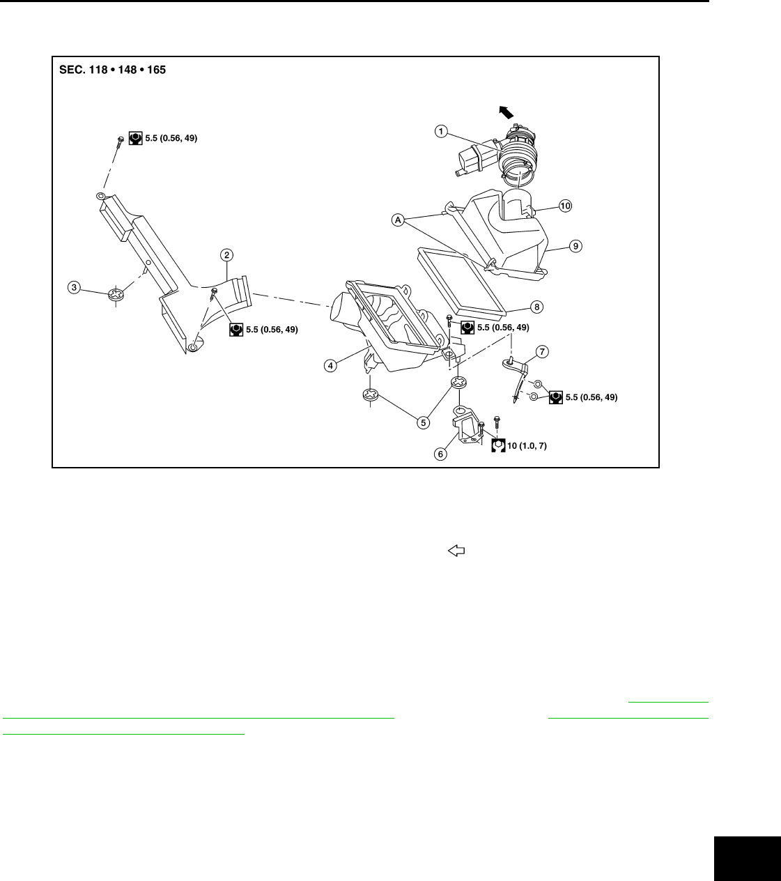
AIR CLEANER FILTER : Exploded View INFOID:0000000011131998
AIR CLEANER FILTER : Removal and Installation INFOID:0000000011131999
REMOVAL
CAUTION:
It is not necessary to remove the front air duct to replace the air cleaner filter.
NOTE:
Replace the air cleaner filter per the periodic maintenance schedule or as necessary. Refer to MA-9, "FOR
USA AND CANADA : Introduction of Periodic Maintenance" (USA and Canada) or MA-12, "FOR MEXICO :
Introduction of Periodic Maintenance" (Mexico).
1. Unhook air cleaner case side clips and lift air cleaner case (upper).
2. Remove the air cleaner filter.
INSTALLATION
Installation is in the reverse order of removal.
ENGINE OIL
ENGINE OIL : Inspection INFOID:0000000011132000
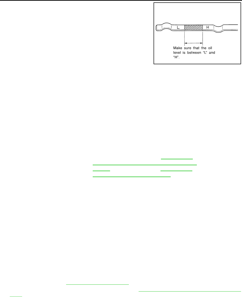
OIL LEVEL
NOTE:
1. Air duct hose and resonator assembly 2. Front air duct 3. Grommet
4. Air cleaner case (lower) 5. Grommets 6. Air cleaner case mounting bracket
7. Bracket 8. Air cleaner filter 9. Air cleaner case (upper)
10. Mass air flow sensor A. Air cleaner case side
clips
To electric throttle control actuator
AWBIA1624ZZ
Revision: August 2014 2015 QX60 NAM
MA-26
< PERIODIC MAINTENANCE >
ENGINE MAINTENANCE (VQ35DE)
• Before starting the engine, check the oil level. If the engine is
already started, stop it and allow 10 minutes before checking.
• Check that the oil level is within the range as indicated on the dip-
stick.
• If it is out of range, add oil as necessary until the dipstick indicates
the correct level.
ENGINE OIL : Changing Engine Oil INFOID:0000000011132001
WARNING:
• Be careful not to burn yourself, as the engine oil may be hot.
• Prolonged and repeated contact with used engine oil may cause skin cancer; try to avoid direct skin
contact with used engine oil. If skin contact is made, wash thoroughly with soap or hand cleaner as
soon as possible.
1. Position the vehicle so it is level on the hoist.
2. Warm up the engine and check for engine oil leaks.
3. Stop engine and wait for 10 minutes.
4. Remove the oil pan drain plug and oil filler cap.
5. Drain the engine oil.
6. Install the oil pan drain plug with a new washer and refill the engine with new engine oil.
CAUTION:
• Be sure to clean the oil pan drain plug and install with a new washer.
• The refill capacity depends on the engine oil temperature and drain time. Use the specifications
for reference only. Always use the dipstick to determine when the proper amount of engine oil is
in the engine.
7. Warm up the engine and check around the oil pan drain plug and oil filter for oil leaks.
8. Stop engine and wait for 10 minutes.
9. Check the engine oil level using the dipstick.
CAUTION:
Do not overfill the engine with engine oil.
OIL FILTER
OIL FILTER : Removal and Installation INFOID:0000000011132002
REMOVAL
1. Drain engine oil. Refer to LU-9, "Changing Engine Oil".
2. Remove front fender protector side cover RH. Refer to EXT-28, "FENDER PROTECTOR : Exploded
View".
JMA122D
Oil specification and viscosity : For North America, refer to MA-16, "FOR
USA AND CANADA : Engine Oil Recommen-
dation". For Mexico, refer to MA-16, "FOR
MEXICO : Fluids and Lubricants".
Oil pan drain plug : 34.3 N·m (3.5 kg-m, 25 ft-lb)
Revision: August 2014 2015 QX60 NAM
ENGINE MAINTENANCE (VQ35DE)
MA-27
< PERIODIC MAINTENANCE >
C
D
E
F
G
H
I
J
K
L
M
B
MA
N
O
A
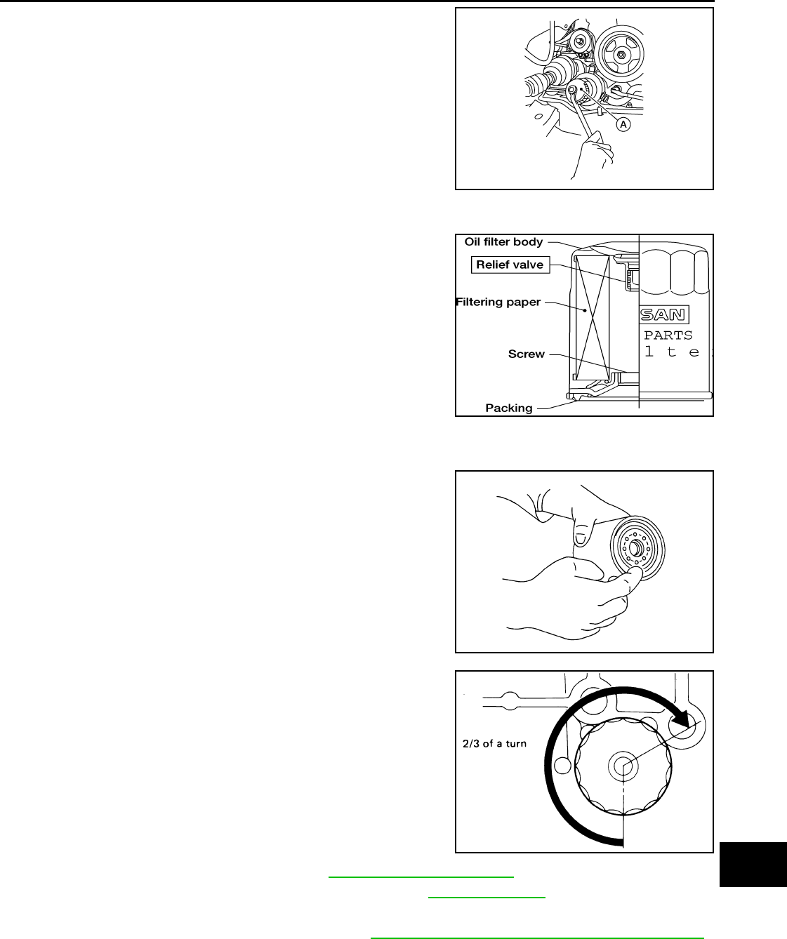
3. Remove the oil filter using Tool (A) as shown.
WARNING:
Be careful not to burn yourself, as the engine oil may be
hot.
CAUTION:
• When removing, prepare a shop cloth to absorb any oil
leaks or spills.
• Do not allow engine oil to adhere to the drive belts.
• Completely wipe off any oil that adheres to the engine and
the vehicle.
• The oil filter is provided with a relief valve. Use a genuine
NISSAN oil filter or equivalent.
INSTALLATION
1. Remove foreign materials adhering to the oil filter installation surface.
2. Apply clean engine oil to the oil seal contact surface of the new
oil filter.
3. Screw the oil filter manually until it touches the installation sur-
face, then tighten it by turning another 2/3 turn or tighten to
specification using Tool.
4. Refill the engine with new engine oil. Refer to LU-9, "Changing Engine Oil".
5. Check the oil level and add engine oil as necessary. Refer to LU-8, "Inspection".
6. After warming up the engine, check for engine oil leaks.
7. Install front fender protector side cover RH. Refer to EXT-28, "FENDER PROTECTOR : Exploded View".
SPARK PLUG
Tool number : KV10115801 (J-38956)
ALBIA0617GB
ALC094
SMA010
Oil filter : 18.0 N·m (1.8 kg-m, 13 ft-lb)
Tool number : KV10115801 (J-38956)
SMA229B
Revision: August 2014 2015 QX60 NAM
MA-28
< PERIODIC MAINTENANCE >
ENGINE MAINTENANCE (VQ35DE)
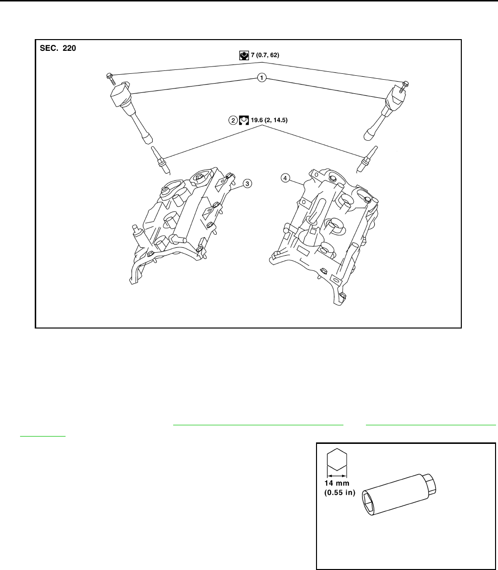
SPARK PLUG : Exploded View INFOID:0000000011132003
SPARK PLUG : Removal and Installation INFOID:0000000011132004
REMOVAL
1. Remove the ignition coil. Refer to EM-42, "Removal and Installation LH" and EM-42, "Removal and Instal-
lation RH".
2. Remove the spark plug with a suitable spark plug wrench.
INSPECTION AFTER REMOVAL
1. Ignition coil 2. Spark plug 3. Rocker cover RH
4. Rocker cover LH
AWBIA0203GB
PBIC2982E
Revision: August 2014 2015 QX60 NAM
ENGINE MAINTENANCE (VQ35DE)
MA-29
< PERIODIC MAINTENANCE >
C
D
E
F
G
H
I
J
K
L
M
B
MA
N
O
A
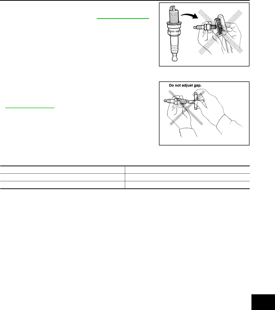
Use the standard type spark plug for normal condition.
CAUTION:
• Do not drop or shock spark plug.
• Do not use a wire brush for cleaning.
• If plug is covered with carbon, a spark plug cleaner may be
used.
• Spark plug gap adjustment is not required between replacement
intervals.
• Measure spark plug gap. When it exceeds the limit, replace spark
plug even if it is within the specified replacement mileage. Refer to
EM-135, "Spark Plug".
INSTALLATION
Installation is in the reverse order of removal.
*: Always check with the Parts Department for the latest parts information.
EVAP VAPOR LINES
EVAP VAPOR LINES : Inspection INFOID:0000000011132005
1. Visually inspect EVAP vapor lines for improper attachment and for cracks, damage, loose connections,
chafing and deterioration.
2. Inspect fuel tank filler cap vacuum relief valve for clogging, sticking, etc.
Spark plug : Refer to EM-135, "Spark Plug".
Cleaner air pressure
: less than 588 kPa (6 kg/cm2,
85 psi)
Cleaning time : less than 20 seconds
SMA773C
SMA806CA
Make DENSO
Standard type* FXE22HR11
Gap (nominal) 1.1 mm (0.043 in)
Revision: August 2014 2015 QX60 NAM
MA-30
< PERIODIC MAINTENANCE >
CHASSIS AND BODY MAINTENANCE
CHASSIS AND BODY MAINTENANCE
IN-CABIN MICROFILTER
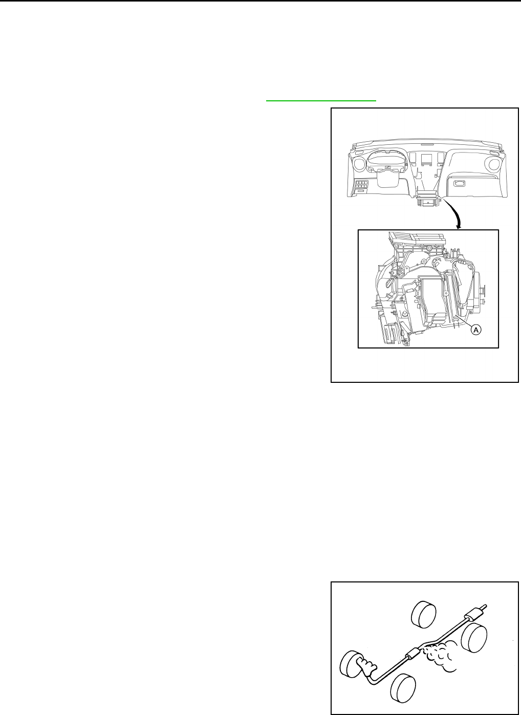
IN-CABIN MICROFILTER : Removal and Installation INFOID:0000000011132006
REMOVAL
1. Remove center console side finisher (RH). Refer to IP-18, "Exploded View".
2. Release the in-cabin microfilter cover tab (A) and remove the
cover from under the RH side of the instrument panel.
CAUTION:
Use care when lifting up on the tab to avoid damaging it.
3. Remove the in-cabin microfilter.
CAUTION:
If the filter is deformed/damaged when removing, replace it with a new one. A deformed or dam-
aged filter may affect the dust collecting performance.
INSTALLATION
Installation is in the reverse order of removal.
CAUTION:
When installing, handle the filter with extreme care to avoid deforming or damaging the filter.
NOTE:
The in-cabin microfilter is marked with an air flow arrow. The end of the microfilter with the arrow should face
the passenger side of the vehicle. The arrow should point towards the rear of the vehicle.
EXHAUST SYSTEM
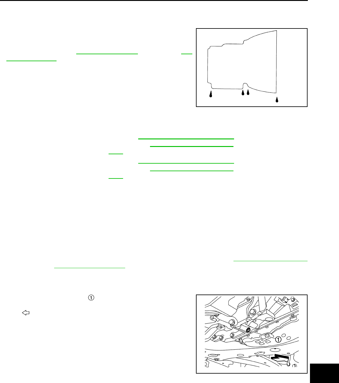
EXHAUST SYSTEM : Inspection INFOID:0000000011132007
Check exhaust pipes, muffler and mounting for improper attachment,
leaks, cracks, damage or deterioration. Repair or replace as neces-
sary.
CVT FLUID
AWIIA1577ZZ
SMA211A
Revision: August 2014 2015 QX60 NAM
CHASSIS AND BODY MAINTENANCE
MA-31
< PERIODIC MAINTENANCE >
C
D
E
F
G
H
I
J
K
L
M
B
MA
N
O
A
CVT FLUID : Inspection INFOID:0000000011132008
FLUID LEAKAGE
• Check transaxle surrounding area (oil seal and plug etc.)for fluid
leakage.
• If anything is found, repair or replace damaged parts and adjust
CVT fluid level. Refer to TM-188, "Adjustment" (RE0F10E) or TM-
400, "Adjustment" (RE0F10J).
CVT FLUID : Changing INFOID:0000000011132009
CAUTION:
• Always use shop paper. Never use shop cloth.
• Replace a drain plug gasket with new ones at the final stage of the operation when installing.
• Use caution when looking into the drain hole as there is a risk of dripping fluid entering the eye.
• After replacement, always perform CVT fluid leakage check.
1. Select “Data Monitor” in “TRANSMISSION” using CONSULT.
2. Select “FLUID TEMP” and confirm that the CVT fluid temperature is 40°C (104°F) or less.
3. Check that the selector lever is in the “P” position, then completely engage the parking brake.
4. Lift up the vehicle.
5. Remove the drain plug and drain the CVT fluid from the oil pan. Refer to TM-199, "Exploded View"
(RE0F10E) or TM-411, "Exploded View" (RE0F10J).
6. Install the drain plug to oil pan.
CAUTION:
Drain plug gasket use the old one.
7. Remove the overflow plug from converter housing.
SMA146B
CVT fluid : Refer to TM-222, "General Specification"
(RE0F10E) or TM-434, "General Specifica-
tion" (RE0F10J).
Fluid capacity : Refer to TM-222, "General Specification"
(RE0F10E) or TM-434, "General Specifica-
tion" (RE0F10J).
: Vehicle front
JSDIA3714ZZ
Revision: August 2014 2015 QX60 NAM
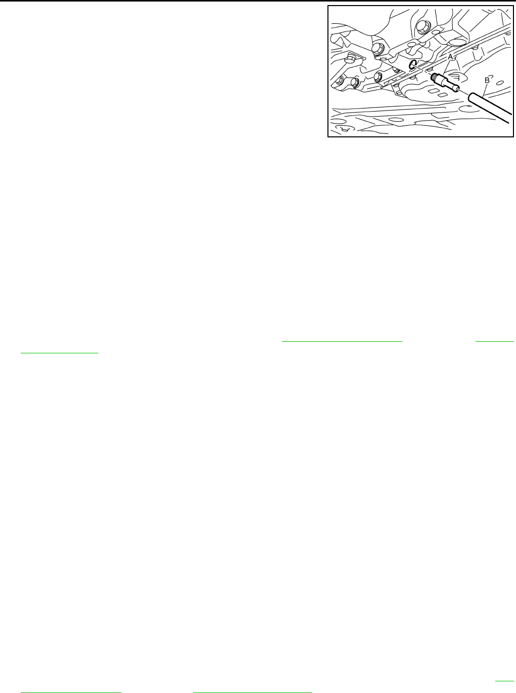
MA-32
< PERIODIC MAINTENANCE >
CHASSIS AND BODY MAINTENANCE
8. Install the charging pipe set (KV311039S0) (A) into the overflow
plug hole.
CAUTION:
Tighten the charging pipe by hand.
9. Install the ATF changer hose (B) to the charging pipe.
CAUTION:
Press the ATF changer hose all the way onto the charging
pipe until it stops.
10. Fill approximately 3 liter (3-1/8 US qt, 2-5/8 lmp qt) of the CVT
fluid.
11. Remove the ATF changer hose and charging pipe, then install
the overflow plug.
NOTE:
Perform this work quickly because CVT fluid leaks.
12. Lift down the vehicle.
13. Start the engine.
14. While depressing the brake pedal, shift the selector lever to the entire position from “P” to “L”, and shift it
to the “P” position.
NOTE:
Hold the lever at each position for 5 seconds.
15. Check that the CONSULT “Data Monitor” in “FLUID TEMP” is 35°C (95°F) to 45°C (113°F).
16. Stop the engine.
17. Lift up the vehicle.
18. Remove the drain plug, and then drain CVT fluid from oil pan.
19. Repeat steps 8 to 18 (one time).
20. Tighten the drain plug to the specified torque. Refer to TM-199, "Exploded View" (RE0F10E) or TM-411,
"Exploded View" (RE0F10J).
21. Remove the overflow plug.
22. Install the charging pipe set (KV311039S0) into the overflow plug hole.
CAUTION:
Tighten the charging pipe by hand.
23. Install the ATF changer hose to the charging pipe.
CAUTION:
Press the ATF changer hose all the way onto the charging pipe until it stops.
24. Fill approximately 3 liter (3-1/8 US qt, 2-5/8 lmp qt) of the CVT fluid.
25. Remove the ATF changer hose and charging pipe, then install the overflow plug.
NOTE:
Perform this work quickly because CVT fluid leaks.
26. Lift down the vehicle.
27. Start the engine.
28. While depressing the brake pedal, shift the selector lever to the entire position from “P” to “L”, and shift it
to the “P” position.
NOTE:
Hold the lever at each position for 5 seconds.
29. Check that the CONSULT “Data Monitor” in “FLUID TEMP” is 35°C (95°F) to 45°C (113°F).
30. Lift up the vehicle.
31. Remove the overflow plug and confirm that the CVT fluid is drained from the overflow plug hole.
CAUTION:
Perform this work with the vehicle idling.
NOTE:
If the CVT fluid is not drained, refer to “Adjustment” and refill with the CVT fluid.
32. When the flow of CVT fluid slows to a drip, tighten the overflow plug to the specified torque. Refer to TM-
199, "Exploded View" (RE0F10E) or TM-411, "Exploded View" (RE0F10J).
CAUTION:
Never reuse O-ring.
JSDIA3713ZZ
Revision: August 2014 2015 QX60 NAM
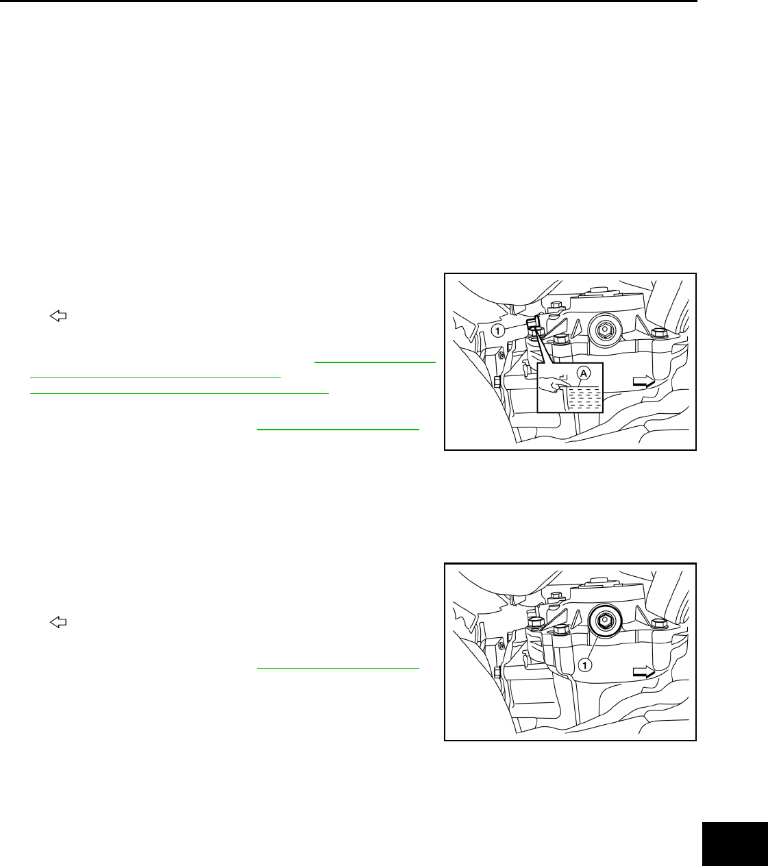
CHASSIS AND BODY MAINTENANCE
MA-33
< PERIODIC MAINTENANCE >
C
D
E
F
G
H
I
J
K
L
M
B
MA
N
O
A
33. Lift down the vehicle.
34. Select “Data Monitor” in “TRANSMISSION” using CONSULT.
35. Select “CONFORM CVTF DETERIORTN”.
36. Select “Erase”.
37. Stop the engine.
TRANSFER OIL
TRANSFER OIL : Inspection INFOID:0000000011132010
TRANSFER OIL LEAKS
Check that transfer oil is not leaking from transfer assembly or around it.
TRANSFER OIL LEVEL
CAUTION:
Do not start engine while checking transfer oil level.
1. Remove filler plug (1) and gasket.
2. Transfer oil level (A) should be level with bottom of filler plug
hole. Add transfer oil if necessary. Refer to MA-15, "FOR USA
AND CANADA : Fluids and Lubricants" (USA and CANADA) or
MA-16, "FOR MEXICO : Fluids and Lubricants" (MEXICO).
3. Set a new gasket onto filler plug, and install it in the transfer and
tighten to specified torque. Refer to DLN-88, "Exploded View".
CAUTION:
Do not reuse gasket.
TRANSFER OIL : Draining INFOID:0000000011132011
CAUTION:
Do not start engine while working.
1. Run the vehicle to warm up the transfer unit sufficiently.
2. Stop the engine and remove drain plug (1) and gasket and drain
the transfer oil.
3. Set a new gasket onto filler plug, and install it in the transfer and
tighten to specified torque. Refer to DLN-88, "Exploded View".
CAUTION:
Do not reuse gasket.
TRANSFER OIL : Refilling INFOID:0000000011132012
CAUTION:
Do not start engine while checking transfer oil level.
: Front
ALDIA0383ZZ
: Front
ALDIA0382ZZ
Revision: August 2014 2015 QX60 NAM
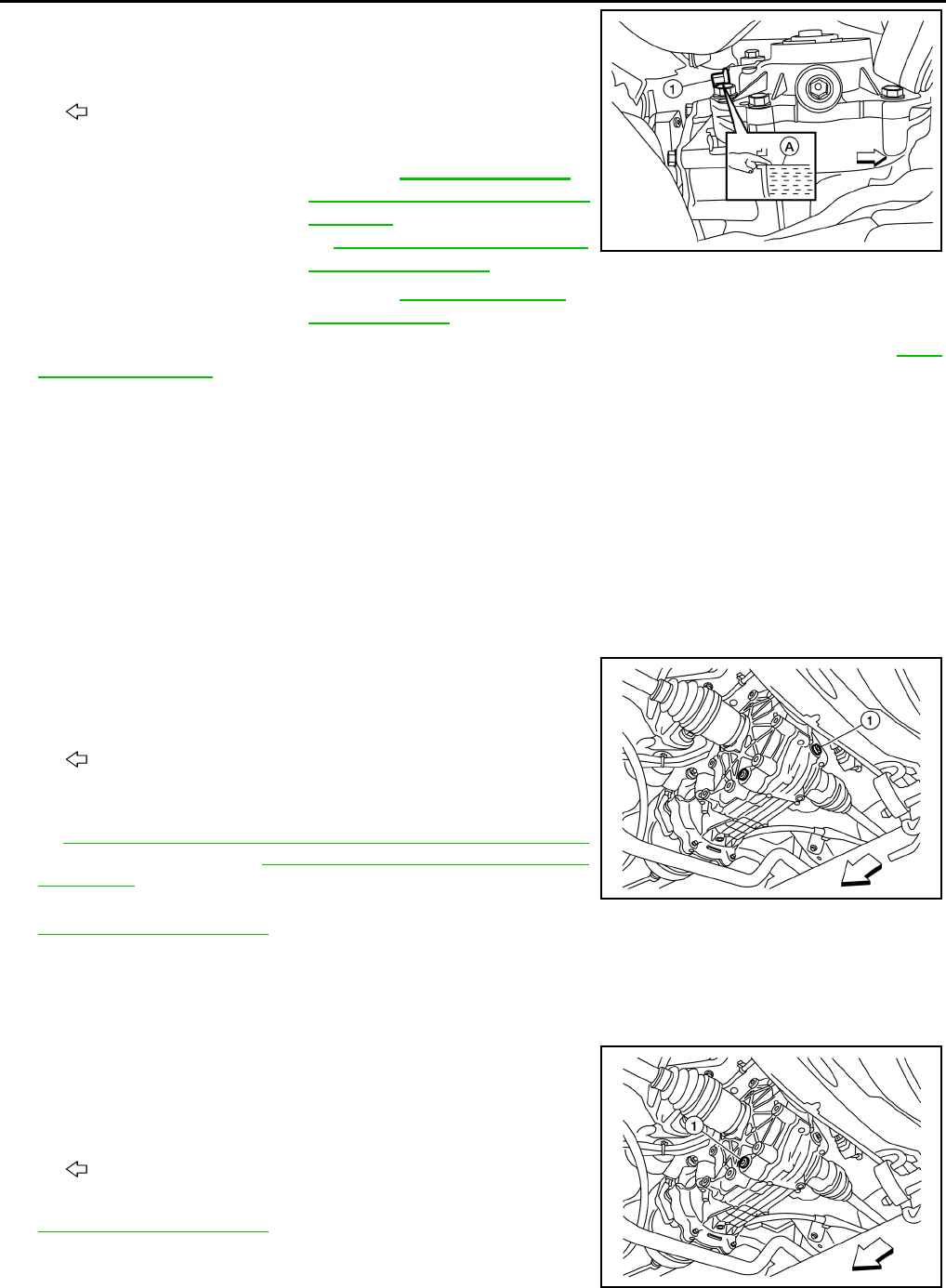
MA-34
< PERIODIC MAINTENANCE >
CHASSIS AND BODY MAINTENANCE
1. Remove filler plug (1).
2. Fill with new transfer oil to the specified level near the filler plug
hole.
3. Set a new gasket onto filler plug, and install it in the transfer and tighten to specified torque. Refer to DLN-
88, "Exploded View".
CAUTION:
Do not reuse gasket.
REAR DIFFERENTIAL GEAR OIL
REAR DIFFERENTIAL GEAR OIL : Inspection INFOID:0000000011132013
REAR DIFFERENTIAL GEAR OIL LEAKS
Check that rear differential gear oil is not leaking from final drive assembly or around it.
REAR DIFFERENTIAL GEAR OIL LEVEL
CAUTION:
Do not start engine while checking rear differential gear oil level.
1. Remove and discard filler plug (1).
CAUTION:
Do not reuse filler plug.
2. Rear differential gear oil level should be level with the bottom of
filler plug hole. Add rear differential gear oil if necessary. Refer
to MA-15, "FOR USA AND CANADA : Fluids and Lubricants"
(USA and CANADA) or MA-16, "FOR MEXICO : Fluids and
Lubricants" (MEXICO).
3. Install filler plug (1) and tighten to specified torque. Refer to
DLN-125, "Exploded View".
REAR DIFFERENTIAL GEAR OIL : Draining INFOID:0000000011132014
CAUTION:
Do not start engine while checking rear differential gear oil level.
1. Remove and discard drain plug (1), and drain rear differential
gear oil.
CAUTION:
Do not reuse drain plug.
2. Install drain plug (1) and tighten to specified torque. Refer to
DLN-125, "Exploded View".
: Front
Transfer oil grade and
viscosity
: Refer to MA-15, "FOR USA
AND CANADA : Fluids and Lu-
bricants" (USA and CANADA)
or MA-16, "FOR MEXICO : Flu-
ids and Lubricants" (MEXICO).
Transfer oil capacity : Refer to DLN-92, "General
Specifications".
ALDIA0383ZZ
: Front
ALDIA0275ZZ
: Front
ALDIA0277ZZ
Revision: August 2014 2015 QX60 NAM
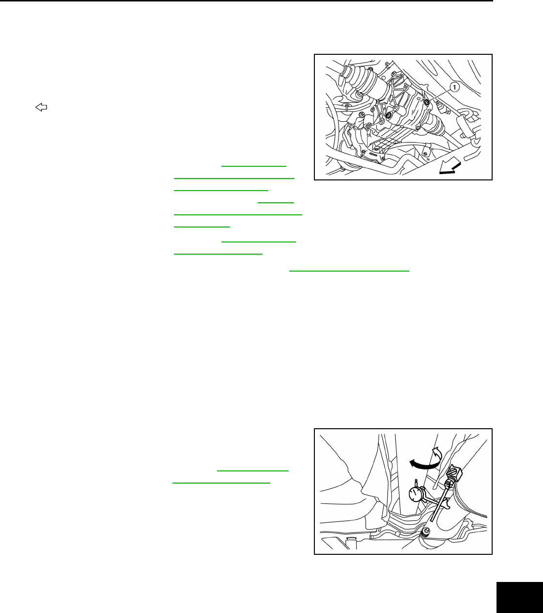
CHASSIS AND BODY MAINTENANCE
MA-35
< PERIODIC MAINTENANCE >
C
D
E
F
G
H
I
J
K
L
M
B
MA
N
O
A
REAR DIFFERENTIAL GEAR OIL : Refilling INFOID:0000000011132015
CAUTION:
Do not start engine while checking rear differential gear oil level.
1. Remove and discard filler plug (1).
CAUTION:
Do not reuse filler plug.
2. Fill with new rear differential gear oil to the specified level near
the filler plug hole.
3. Install filler plug (1) and tighten to specified torque. Refer to DLN-125, "Exploded View".
PROPELLER SHAFT
PROPELLER SHAFT : Inspection INFOID:0000000011132016
APPEARANCE AND NOISE INSPECTION
• Inspect the propeller shaft tube for dents or cracks. If damaged, replace the propeller shaft assembly.
• Check bearings for noise or damage. If damaged, replace as necessary.
PROPELLER SHAFT VIBRATION
NOTE:
If vibration is present at high speed, check propeller shaft runout first, then check mounting between propeller
shaft and companion flange.
1. Measure the runout of the propeller shaft tube at several points
by rotating the final drive companion flange with your hands.
: Front
Rear differential gear oil
grade and viscosity
: Refer to MA-15, "FOR
USA AND CANADA : Flu-
ids and Lubricants" (USA
and CANADA) or MA-16,
"FOR MEXICO : Fluids and
Lubricants" (MEXICO).
Rear differential gear oil
capacity
: Refer to DLN-130, "Gen-
eral Specification".
ALDIA0275ZZ
Propeller shaft runout : Refer toDLN-101, "Pro-
peller Shaft Runout".
ALDIA0280ZZ
Revision: August 2014 2015 QX60 NAM
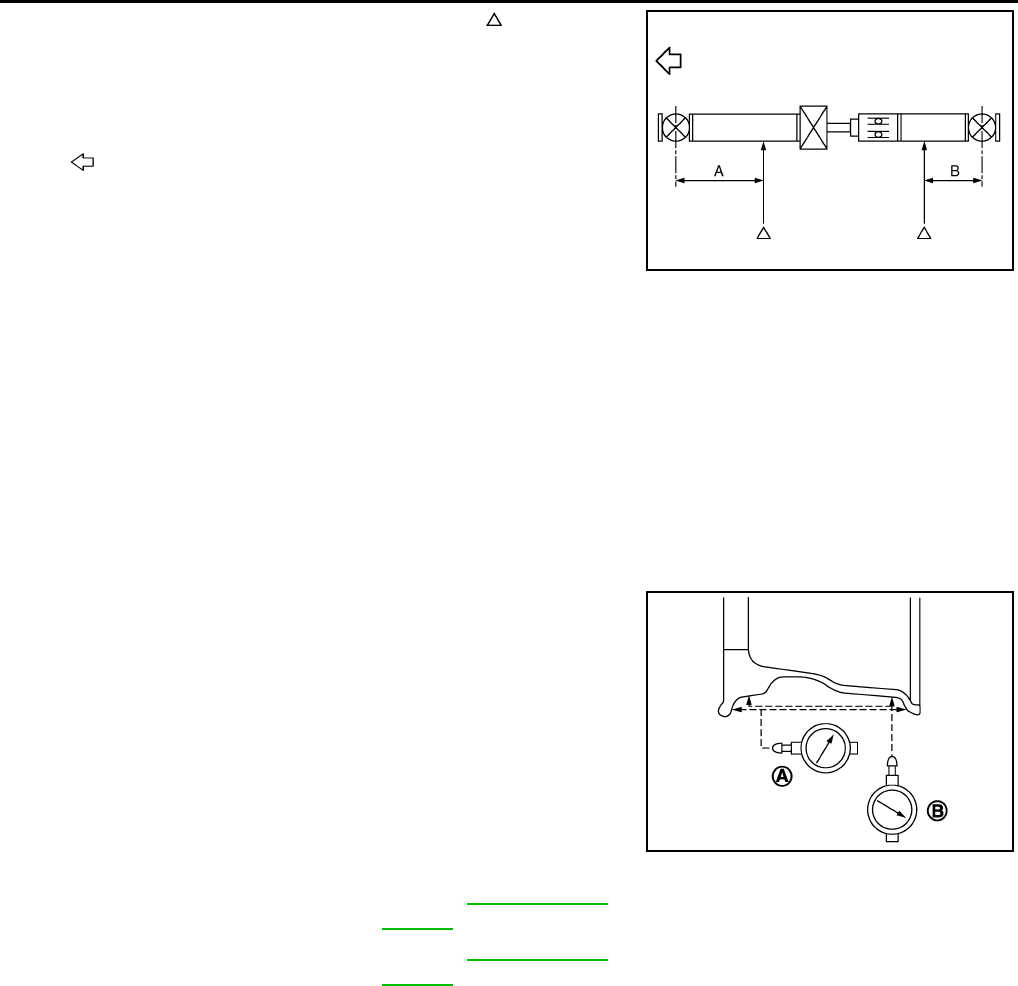
MA-36
< PERIODIC MAINTENANCE >
CHASSIS AND BODY MAINTENANCE
• Propeller shaft runout measuring point (Point “ ”).
2. If the runout still exceeds specifications, disconnect the propeller shaft at the final drive companion flange;
then rotate the companion flange 90°, 180°, 270° and reconnect propeller shaft.
3. Check the runout again. If the runout still exceeds specifications, replace the propeller shaft assembly.
4. After installation, check for vibration by driving the vehicle.
WHEELS
WHEELS : Inspection INFOID:0000000011132017
1. Check tires for wear and improper inflation.
2. Check wheels for deformation, cracks and other damage. If deformed, remove wheel and check wheel
runout.
3. Remove tire from wheel and mount wheel on a tire balance
machine.
CAUTION:
DO NOT use center hole cone-type clamping machines to
hold the wheel assembly during tire removal/installation or
balancing or damage to the wheel paint, cladding or chrome
may result. Use only rim-type or universal lug-type clamp-
ing machines to hold the wheel assembly during servicing.
a. Set dial indicator as shown.
b. Check runout, if the lateral runout (A) or radial runout (B)
exceeds the limit, replace wheel.
WHEELS : Adjustment INFOID:0000000011132018
BALANCING WHEELS (ADHESIVE WEIGHT TYPE)
Preparation Before Adjustment
Remove inner and outer balance weights from the road wheel. Using releasing agent, remove double-faced
adhesive tape from the road wheel.
CAUTION:
• Be careful not to scratch the road wheel during removal.
• After removing double-faced adhesive tape, wipe clean all traces of releasing agent from the road
wheel.
Wheel Balance Adjustment
• If a balancer machine has an adhesive weight mode setting, select the adhesive weight mode setting and
skip Step 2 below. If a balancer machine only has the clip-on (rim flange) weight mode setting, follow Step 2
to calculate the correct size adhesive weight.
1. Set road wheel on balancer machine using the center hole as a guide. Start the balancer machine.
Dimension (A) : 612.0 mm (24.09 in)
Dimension (B) : 474.5 mm (18.68 in)
: Front
JPDID0156ZZ
Lateral runout (A) Refer to WT-61, "Road
Wheel"
Radial runout (B) Refer to WT-61, "Road
Wheel"
SEIA0737E
Revision: August 2014 2015 QX60 NAM
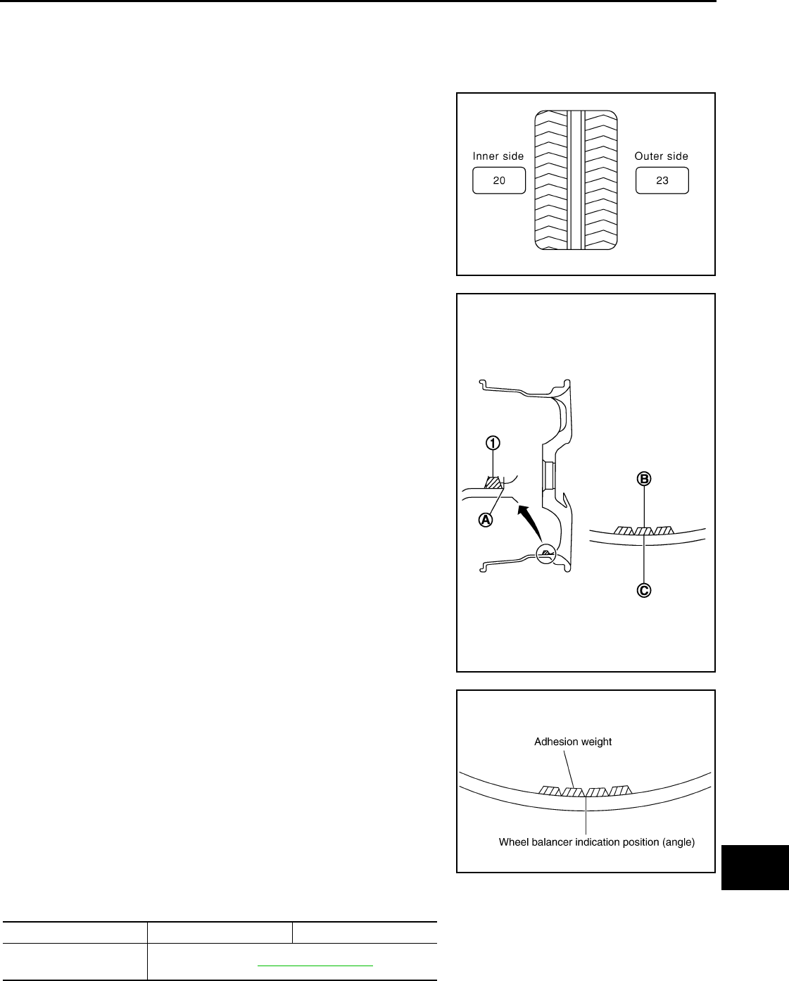
CHASSIS AND BODY MAINTENANCE
MA-37
< PERIODIC MAINTENANCE >
C
D
E
F
G
H
I
J
K
L
M
B
MA
N
O
A
2. For balancer machines that only have a clip-on (rim flange) weight mode setting, follow this step to calcu-
late the correct size adhesive weight to use. When inner and outer imbalance values are shown on the
balancer machine indicator, multiply outer imbalance value by 5/3 (1.67) to determine balance weight that
should be used. Select the outer balance weight with a value closest to the calculated value above and
install in to the designated outer position of or at the designated angle in relation to the road wheel.
a. Indicated imbalance value × 5/3 = balance weight to be installed
Calculation example:
23 g (0.81 oz) × 5/3 (1.67) = 38.33 g (1.35 oz) ⇒ 40 g (1.41 oz)
balance weight (closer to calculated balance weight value)
NOTE:
Note that balance weight value must be closer to the calculated
balance weight value.
Example:
37.4 ⇒ 35 g (1.23 oz)
37.5 ⇒ 40 g (1.41 oz)
3. Install balance weight in the position shown.
CAUTION:
• Do not install the inner balance weight before installing
the outer balance weight.
• Before installing the balance weight, be sure to clean the
mating surface of the road wheel.
• When installing balance weight (1) to road wheel, set it into the
grooved area (A) on the inner wall of the road wheel as shown
so that the balance weight center (B) is aligned with the bal-
ancer machine indication position (angle) (C).
CAUTION:
• Always use genuine NISSAN adhesive balance weights.
• Balance weights are non-reusable; always replace with
new ones.
• Do not install more than three sheets of balance
weights.
4. If calculated balance weight value exceeds 50 g (1.76 oz), install
two balance weight sheets in line with each other as shown.
CAUTION:
Do not install one balance weight sheet on top of another.
5. Start balancer machine again.
6. Install balance weight on inner side of road wheel in the bal-
ancer machine indication position (angle).
CAUTION:
Do not install more than two balance weights.
7. Start balancer machine. Make sure that inner and outer residual
imbalance values are 5 g (0.17 oz) each or below.
8. If either residual imbalance value exceeds 5 g (0.17 oz), repeat installation procedures.
SMA054D
JPEIC0040ZZ
Wheel balance Dynamic (At flange) Static (At flange)
Maximum allowable im-
balance Refer to WT-61, "Road Wheel".
PEIA0033E
Revision: August 2014 2015 QX60 NAM
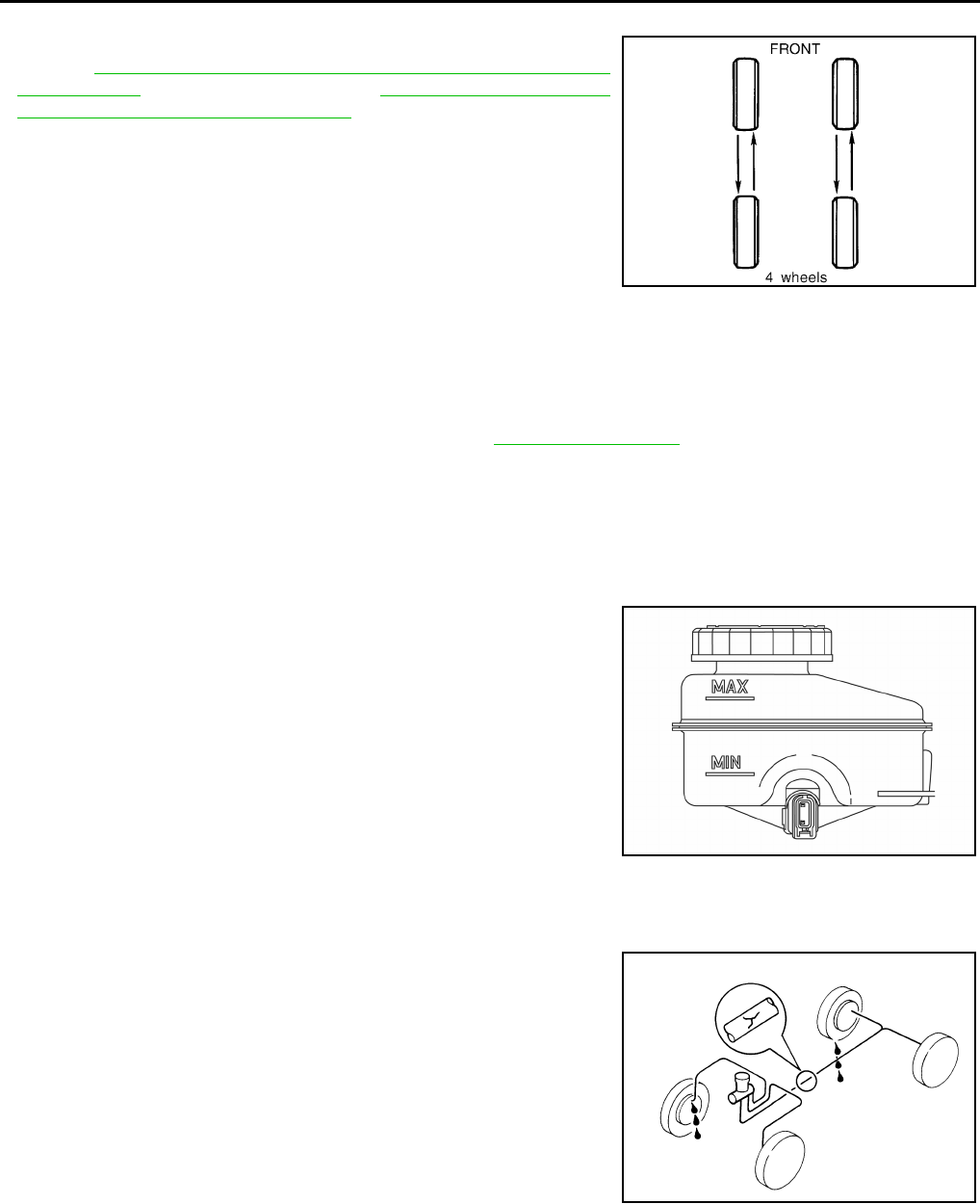
MA-38
< PERIODIC MAINTENANCE >
CHASSIS AND BODY MAINTENANCE
TIRE ROTATION
• Follow the maintenance schedule for tire rotation service intervals.
Refer to MA-9, "FOR USA AND CANADA : Introduction of Periodic
Maintenance" (USA and CANADA) or MA-12, "FOR MEXICO :
Introduction of Periodic Maintenance" (MEXICO).
• When installing the wheel, tighten wheel nuts to the specified
torque.
CAUTION:
• Do not include the spare tire when rotating the tires.
• When installing wheels, tighten them diagonally by dividing
the work two to three times in order to prevent the wheels
from developing any distortion.
• Be careful not to tighten wheel nut at torque exceeding the
criteria for preventing strain of disc rotor.
• Use NISSAN genuine wheel nuts for aluminum wheels.
• Perform the ID registration after tire rotation. Refer to WT-24, "Description".
BRAKE FLUID LEVEL AND LEAKS
BRAKE FLUID LEVEL AND LEAKS : Inspection INFOID:0000000011132019
BRAKE FLUID LEVEL
• Make sure that the brake fluid level in the reservoir sub tank is
between the MAX and MIN lines.
• Visually check around the reservoir sub tank and reservoir tank for
brake fluid leakage.
• If the brake fluid level is excessively low, check the brake system
for leakage.
• If brake warning lamp remains illuminated after parking brake
pedal is released, check the brake system for brake fluid leakage.
BRAKE LINE
1. Check brake line (tubes and hoses) for cracks, deterioration or other damage. Replace any damaged
parts.
2. Check for brake fluid leakage by fully depressing brake pedal
while engine is running.
CAUTION:
If brake fluid leakage occurs around joints, retighten or
replace damaged parts as necessary.
BRAKE LINES AND CABLES
Wheel nut tightening
torque
: 113 N·m (12 kg-m, 83 ft-lb)
SMA829C
ALFIA0249ZZ
SBR389C
Revision: August 2014 2015 QX60 NAM
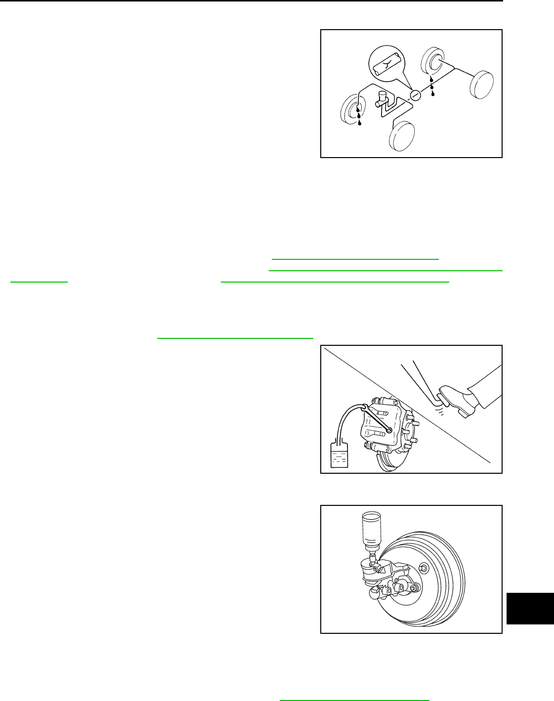
CHASSIS AND BODY MAINTENANCE
MA-39
< PERIODIC MAINTENANCE >
C
D
E
F
G
H
I
J
K
L
M
B
MA
N
O
A
BRAKE LINES AND CABLES : Inspection INFOID:0000000011132020
• Check brake fluid lines and parking brake cables for improper
attachment, leaks, chafing, abrasions, deterioration, etc.
BRAKE FLUID
BRAKE FLUID : Drain and Refill INFOID:0000000011132021
CAUTION:
• Do not spill or splash brake fluid on painted surfaces. Brake fluid may damage paint. If brake fluid is
splashed on painted areas, wash it away with water immediately.
• Prior to repair, turn the ignition switch OFF, disconnect the ABS actuator and electric unit (control
unit) connector or negative battery terminal. Refer to PG-99, "Removal and Installation".
• Refill brake system with new brake fluid. Refer to MA-15, "FOR USA AND CANADA : Fluids and
Lubricants" (United States and Canada) or MA-16, "FOR MEXICO : Fluids and Lubricants" (Mexico).
• Do not reuse drained brake fluid.
DRAINING
1. Turn ignition switch OFF and disconnect ABS actuator and electric unit (control unit) connector or nega-
tive battery terminal. Refer to PG-99, "Removal and Installation".
2. Connect a vinyl tube to bleeder valve.
3. Depress brake pedal, loosen bleeder valve, and gradually
remove brake fluid.
REFILLING
1. Make sure no foreign material is in the reservoir sub-tank, and
refill with new brake fluid.
CAUTION:
Do not reuse drained brake fluid.
2. Refill the brake system as follows:
• Depress the brake pedal.
• Loosen bleeder valve.
• Slowly depress brake pedal to 2/3 of the brake pedal full
stroke.
• Tighten bleeder valve.
• Release brake pedal.
Repeat this operation at intervals of two or three seconds until
all old brake fluid is discharged. Add new brake fluid to master cylinder reservoir sub tank frequently.
CAUTION:
Do not allow master cylinder reservoir to empty as this may cause damage to master cylinder
internal components.
3. Bleed the air out of the brake hydraulic system. Refer to BR-16, "Bleeding Brake System".
SBR389C
BRA0007D
PFIA0403J
Revision: August 2014 2015 QX60 NAM
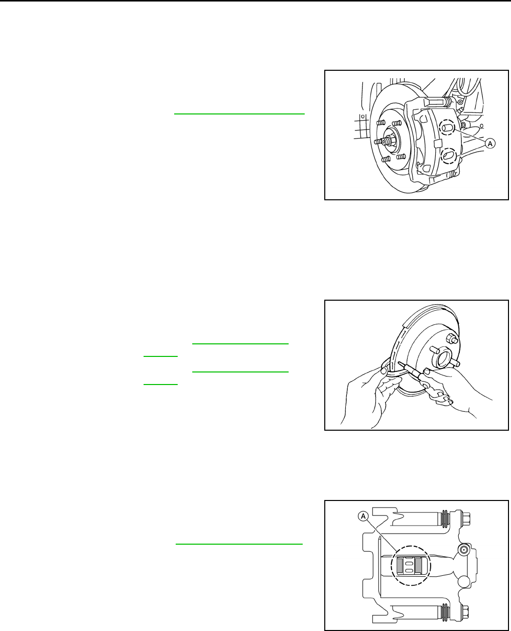
MA-40
< PERIODIC MAINTENANCE >
CHASSIS AND BODY MAINTENANCE
FRONT BRAKE
FRONT BRAKE : Inspection of Pad INFOID:0000000011132022
Check brake pad wear thickness from an inspection hole (A) on cyl-
inder body. Check using a scale if necessary.
FRONT BRAKE : Inspection of Rotor INFOID:0000000011132023
VISUAL
Check surface of disc rotor for uneven wear, cracks or damage. Replace if any abnormal conditions exist.
THICKNESS
Check the thickness of the disc rotor using a micrometer. Replace
the disc rotor if the thickness is below the wear limit.
REAR BRAKE
REAR BRAKE : Inspection of Pad INFOID:0000000011132024
INSPECTION
Check brake pad wear thickness from an inspection hole (A) on cyl-
inder body. Check using a scale if necessary.
REAR BRAKE : Inspection of Rotor INFOID:0000000011132025
VISUAL
Check surface of disc rotor for uneven wear, cracks or damage. Replace if any abnormal conditions exist.
THICKNESS
Wear thickness : Refer to BR-49, "Front Disc Brake".
AWFIA0891ZZ
Wear thickness : Refer to BR-49, "Front Disc
Brake".
Thickness variation : Refer to BR-49, "Front Disc
Brake".
SBR020B
Wear thickness : Refer to BR-49, "Rear Disc Brake".
ALFIA0226ZZ
Revision: August 2014 2015 QX60 NAM
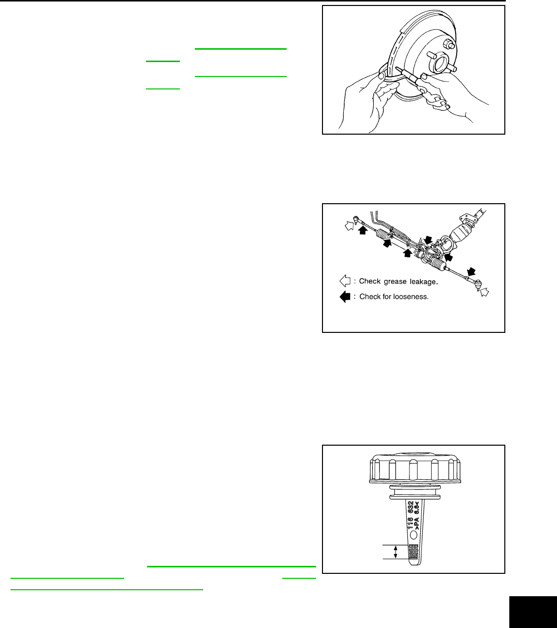
CHASSIS AND BODY MAINTENANCE
MA-41
< PERIODIC MAINTENANCE >
C
D
E
F
G
H
I
J
K
L
M
B
MA
N
O
A
Check the thickness of the disc rotor using a micrometer. Replace
the disc rotor if the thickness is below the minimum thickness.
STEERING GEAR AND LINKAGE
STEERING GEAR AND LINKAGE : Inspection INFOID:0000000011132026
STEERING GEAR
• Check gear housing and boots for looseness, damage and grease
leakage.
• Check connection with steering column for looseness.
STEERING LINKAGE
Check ball joint, dust cover and other component parts for looseness, wear, damage and grease leakage.
POWER STEERING FLUID AND LINES
POWER STEERING FLUID AND LINES : Inspection INFOID:0000000011132027
FLUID LEVEL
Check power steering fluid level at the scale on reservoir tank cap
indicator.
• Check power steering fluid level with engine stopped and the fluid
temp between 0 – 30° C (32 – 86° F).
• Power steering fluid level should be between the hatching area of
the indicator on the power steering reservoir tank cap.
CAUTION:
• Do not overfill.
• Do not reuse used power steering fluid.
• Recommended power steering fluid is Genuine NISSAN E-
PSF or equivalent. Refer to MA-15, "FOR USA AND CANADA :
Fluids and Lubricants" (United States and Canada) or MA-16,
"FOR MEXICO : Fluids and Lubricants" (Mexico).
FLUID LEAKAGE
Minimum thickness : Refer to BR-49, "Rear Disc
Brake".
Thickness variation : Refer to BR-49, "Rear Disc
Brake".
SBR020B
SLIA0014E
ALGIA0125ZZ
Revision: August 2014 2015 QX60 NAM
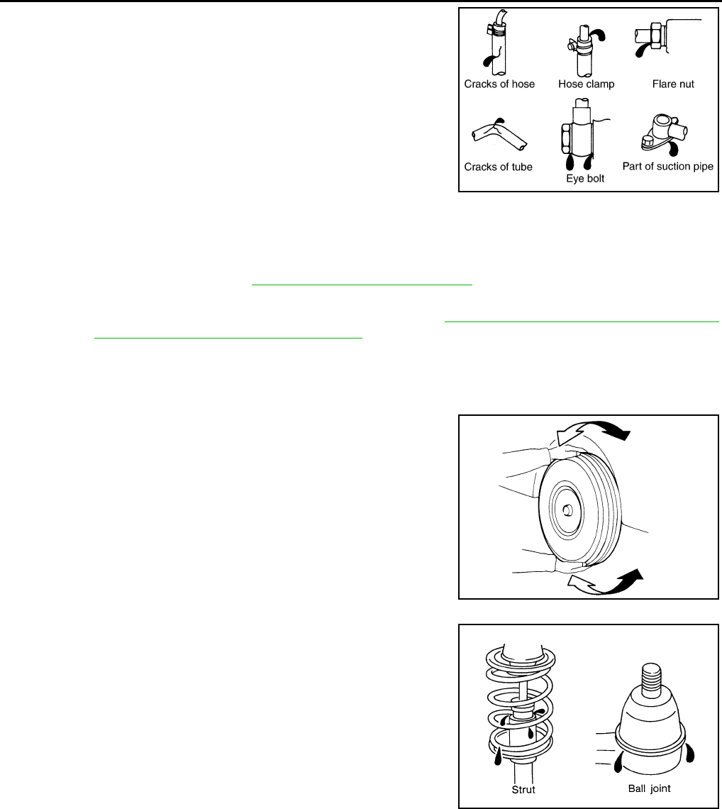
MA-42
< PERIODIC MAINTENANCE >
CHASSIS AND BODY MAINTENANCE
Check the power steering hydraulic system for leaks, cracks, dam-
age, loose connections, chafing or deterioration. Repair or replace
as necessary.
1. Start engine and allow engine to idle.
2. Turn steering wheel right-to-left several times.
3. Hold steering wheel at each “lock” position for five seconds to
check fluid leakage.
CAUTION:
Do not hold steering wheel in a locked position for more
than 10 seconds. Damage to power steering oil pump may
occur.
4. If power steering fluid leakage at connections is noticed, loosen flare nut and retighten.
CAUTION:
Do not over tighten flare nut as damage to O-ring and connection can occur.
5. If power steering fluid leakage from the power steering oil pump is noticed, repair connection or replace
power steering oil pump. Refer to ST-55, "Removal and Installation".
6. Check steering gear boots for accumulation of power steering fluid. Power steering fluid indicates a leak
from the power steering gear, replace as necessary. Refer to ST-60, "Removal and Installation - FWD"
(FWD) or ST-62, "Removal and Installation - AWD" (AWD).
AXLE AND SUSPENSION PARTS
AXLE AND SUSPENSION PARTS : Inspection INFOID:0000000011132028
Check front and rear axle and suspension parts for excessive play,
cracks, wear or other damage.
• Shake each wheel to check for excessive play.
• Check wheel bearings for smooth operation.
• Check axle and suspension nuts and bolts for looseness.
• Check strut (shock absorber) for oil leakage or other damage.
• Check suspension ball joint for grease leakage and ball joint dust
cover for cracks or other damage.
DRIVE SHAFT
SGIA0506E
SMA525A
SFA392B
Revision: August 2014 2015 QX60 NAM
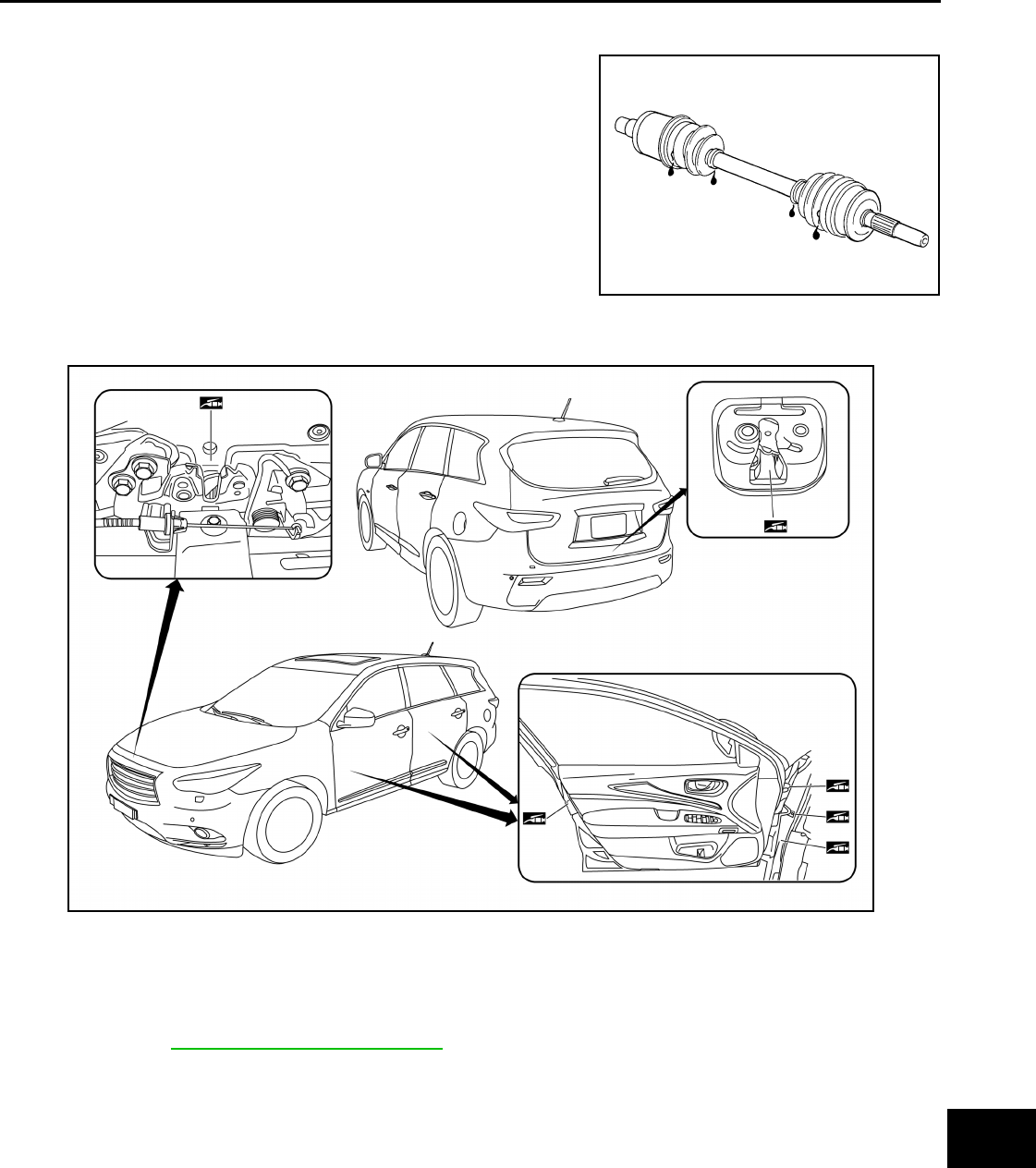
CHASSIS AND BODY MAINTENANCE
MA-43
< PERIODIC MAINTENANCE >
C
D
E
F
G
H
I
J
K
L
M
B
MA
N
O
A
DRIVE SHAFT : Inspection INFOID:0000000011132029
Check boot and drive shaft for cracks, wear, damage and grease
leakage.
LOCKS, HINGES AND HOOD LATCH
LOCKS, HINGES AND HOOD LATCH : Lubricating INFOID:0000000011132030
SEAT BELT, BUCKLES, RETRACTORS, ANCHORS AND ADJUSTERS
SEAT BELT, BUCKLES, RETRACTORS, ANCHORS AND ADJUSTERS : Inspection
INFOID:0000000011132031
For details, refer to SBC-54, "Diagnosis Procedure" in SB section.
• Check anchors for loose mounting.
• Check belts for damage.
• Check retractor for smooth operation.
• Check function of buckles and tongues when buckled and released.
CAUTION:
• After any collision, inspect all seat belt assemblies, including retractors and other attached hard-
ware (i.e., anchor bolt, guide rail set). INFINITI recommends replacing all seat belt assemblies in use
during a collision, unless not damaged and properly operating after minor collision.
Also inspect seat belt assemblies not in use during a collision and replace if damaged or improperly
operating.
Seat belt pre-tensioner should be replaced even if the seat belts are not in use during a frontal colli-
sion where the driver and passenger air bags are deployed.
SFA108A
AWBIA1222GB
Revision: August 2014 2015 QX60 NAM

MA-44
< PERIODIC MAINTENANCE >
CHASSIS AND BODY MAINTENANCE
• If any component of seat belt assembly is questionable, do not repair.
Replace as seat belt assembly.
• If webbing is cut, frayed, or damaged, replace belt assembly.
• Do not oil tongue and buckle.
• Use a genuine INFINITI seat belt assembly.
Revision: August 2014 2015 QX60 NAM
