Infinity Speaker Il60 L R Users Manual
IL60 LR to the manual aed3d688-1768-4c5e-89b2-26050723a2ca
2015-01-23
: Infinity Infinity-Speaker-Il60-L-R-Users-Manual-342652 infinity-speaker-il60-l-r-users-manual-342652 infinity pdf
Open the PDF directly: View PDF ![]() .
.
Page Count: 41

Interlude Series
IL60 L/R
Powered Loudspeaker
Service Manual
Infinity Systems, Inc
250 Crossways Park Dr.
Woodbury, New York 11797
REV 5 5/2005

IL60
CONTENTS
SPECIFICATIONS …….……………………………………………….3
DETAILED SPECIFICATIONS …………………….…………………4
CONTROLS and CONNECTIONS …………………….….…………6
OPERATION……………………………………..………..…….……..10
BASS OPTIMIZATION SYSTEM……………………….….…………10
MECHANICAL PARTS LIST…………………….……………………12
EXPLODED VIEW ……………………………………….……………13
EXPLODED VIEW OF AMPLIFIER…………………….……………14
SERVICE TIPS……………………………..……………………….…15
TEST SET UP PROCEDURE……………………..…….……………16
IL60 ADJUST BIAS PROCEDURE………………..…………………17
SERVICE BULLETIN INF2000-04…….…………….….……………18
SERVICE BULLETIN INF2001-04…….…………….….……………19
TECH TIP INFTT2003-03…….…………….…………………………21
PACKAGING …………………………….………………………….…22
PRINTED CIRCUIT BOARD DIAGRAMS………………..…………23
ELECTRICAL PARTS LIST (120v)…………………….….…………27
INTEGRATED CIRCUIT DIAGRAMS ………………………………33
WIRING DIAGRAM CROSSOVER NETWORK SCHEMATIC..….34
IL60 SCHEMATICS…………..………….……………………………35
2

IL60 L/R
3
Specifications
IL60 L/R Frequency Response: 28Hz - 22,000Hz (±3dB)
Recommended Amplifier Power Range 15-175 watts*
Subwoofer Amplifier Output: 500 watts (In to 8Ωfrom 20 Hz - 100Hz
with no more than 0.1% THD)
Sensitivity: 89dB (2.83V @ 1 meter)
Nominal Impedance: 8Ω
Crossover Frequencies: 150Hz; 500Hz,2800Hz, 24dB/octave
Low-Frequency Driver: 12" C.M.M.D., magnetically shielded
Mid-Bass Driver: 6-1/2” C.M.M.D., magnetically shielded
Midrange Driver: 4” C.M.M.D., magnetically shielded
High-Frequency Driver: 1” C.M.M.D., magnetically shielded
Dimensions (H x W x D): 48" x 9-1/4" x 17-1/4"
(1219mm x 235mm x 438mm)
Weight: 75 lb (34kg)
* The maximum recommended amplifier power rating will ensure proper system headroom to allow
for occasional peaks. We do not recommend sustained operation at these maximum power levels.
Detailed Specifications
IL60 L/R
4
IL60 L/R
5
Detailed Specifications (Cont.)
IL60 L/R
6
Controls and Connections
IL60 L/R
7
Controls and Connections
SPEAKER
OUTPUTS
+- +-
SPEAKER
OUTPUTS
+- +-
(ONE CHANNEL SHOWN)
AMPLIFIER/RECEIVER
LEFT RIGHT
AMPLIFIER/RECEIVER
SPEAKER OUTPUTS
(ONE CHANNEL SHOWN)
PREAMP OUTPUTS AMPLIFIER INPUTS
L
RR
L
®
O
+
1. LOOSEN TERMINALS
2. INSERT BARE END:
TIGHTEN TERMINALS
3. SET
INPUT SUB
TO "LINE LEVEL"
4. SET
LOW-PASS FILTER
"ON"
METHOD 2
NO STRIPE = -
BLACK = -
STRIPE= +
RED = +
O
00354
+
®
00359-2
1. LOOSEN TERMINALS
2. INSERT BARE END:
TIGHTEN TERMINALS
3. SET
INPUT SUB
TO "SPEAKER"
4. SET
LOW-PASS FILTER
"ON"
METHOD 1
NO STRIPE = -
BLACK = -
STRIPE= +
RED = +
AC CORD
AC CORD
The Interlude IL50 and IL60 offer unprecedented flexibility for connecting the
system to any type of audio or home-theater system. Consult the table at right
to determine which system description most closely matches your own, then
follow the hook-up method corresponding to that system.
If none of these system configurations seem to match yours, consult your dealer
or Infinity customer service for direction on how best to hook up your system.
For methods 2, 3a, 3b and 4, make sure all bass-management features are
properly set. The Audio channels should all be set to “Small” or “High-Pass”
and the subwoofer set to “On.”
2-Channel receiver or integrated amplifier 1
that has no subwoofer output or
Pre-out/Main-In connectors
2-Channel receiver or integrated amplifier 2
with preamp output and input connectors
2-Channel system with separate preamplifier 2
and power amplifier
Dolby* Pro Logic* with THX®, Dolby Digital, 3a
or DTS®receiver with a filtered subwoofer
(or LFE) output connector
Dolby Digital or DTS processor with separate 3b
power amplifiers or multichannel amplifier
Non-THX certified Dolby Pro Logic receiver 4
with full-range subwoofer outputs
System Type Connection
Methods
4
3
4
3
IL60 L/R
8
METHOD 3a
NO STRIPE = -
BLACK = -
STRIPE= +
RED = +
O
00354
+
®
O
+
®
STRIPE = +
METHOD 3b
BLACK = -
NO STRIPE = -
RED = +
Controls and Connections (Cont.)
4
4
3
3
IL60 L/R
9
Controls and Connections (Cont.)
+-
SUBWOOFER
OUTPUTS
(ONE CHANNEL SHOWN)
RECEIVER
SPEAKER
OUTPUTS
L
R
O
+
®
1. LOOSEN TERMINALS
2. INSERT BARE END:
TIGHTEN TERMINALS
3. SET
INPUT SUB
TO "LINE LEVEL"
4. SET
LOW-PASS FILTER
TO "ON"
METHOD 4
STRIPE = +
NO STRIPE= -
BLACK = -
RED = +
AC CORD
00395-4
Final Positioning
After correctly connecting the loudspeaker and
verifying that both the subwoofer and main section
portions are playing, it is time to optimize the
system for your particular listening room.
Earlier, you placed the loudspeakers in their general
location. Finding the exact location for optimum
performance sometimes only involves moving the
speakers a few inches in any direction. We urge
you, therefore, to experiment with placement until
your speakers deliver their full potential. When the
speakers are moved inward (toward each other)
there is generally better focus of instruments and
vocalists; however, moving the speakers too close
together can reduce the spaciousness of the stage
effect and you may need to experiment with the
trade-off between focus and imaging. If your
listening room is larger than average and your
listening position is relatively far from the speakers,
wider placement of the speakers may be required.
3
4
IL60 L/R
10
Operation/Bass Optimization SystemTM

IL60 L/R
11
Bass Optimization SystemTM (Cont.)
NOTE:It is important that you make the same adjustments to both loudspeakers.
Set the Bass Optimization System Bandwidth adjustments to a middle position (10 clicks from a
fully clockwise position) and set Level adjustments for a –6dB (8 clicks from a fully clockwise
position). Then,while the music is playing,sit in your favorite chair and have somebody else slowly
adjust the Frequency controls from fully clockwise to fully counter-clockwise. At a certain
frequency, you should hear the problem lessen and the overall bass performance improve. When
you are satisfied that you have found the best frequency, have your assistant vary the Levels
slowly up and down until you have maximized the improvement.If you have really keen ears, you
can also have the Bandwidth controls adjusted for maximum benefit.
While the Bass Optimization System allows the listener to fine-tune the bass response to sound best
in a particular room,some listeners don’t have the skill or desire to adjust their system by ear. In
order to facilitate quicker and more accurate results, Infinity has developed an optional test and
measurement kit that allows the user to perform a series of measurements and aids him/her in
properly setting the Bass Optimization System controls. With the addition of this kit,the Bass
Optimization System becomes truly room-adaptive.
The kit consists of the following:a test CD, a sound-level meter that is specifically calibrated for low
frequencies, and something we call a “Q-Finder, ”a device to help find the width of the measured
curve and, finally, a measurement template. It works as follows. The listener plays the tones from
the test CD and records the relative output level of each test tone, using the sound-level meter, on
the provided measurement template. After all the tones are complete, the template contains a
response curve for the frequencies below 100Hz. The user simply notes the frequency of the largest
bass peak,calculates the correct amount of attenuation,and uses the “Q-Finder” to determine the
width of the curve. These three values are dialed into the Bass Optimization System controls located
on the speaker.The entire process takes less than twenty minutes.
If your dealer does not stock the Bass Optimization System test and measurement kit,you may
purchase it directly from Infinity. U.S. residents can visit our Web site at www.infinitysystems.com or
call 1-800-553-3332.Canadian residents should contact their dealer or call 1-800-567-3275.
Ask for Infinity part number 335852-002.
11
10
9
10
11

IL60 L/R
12
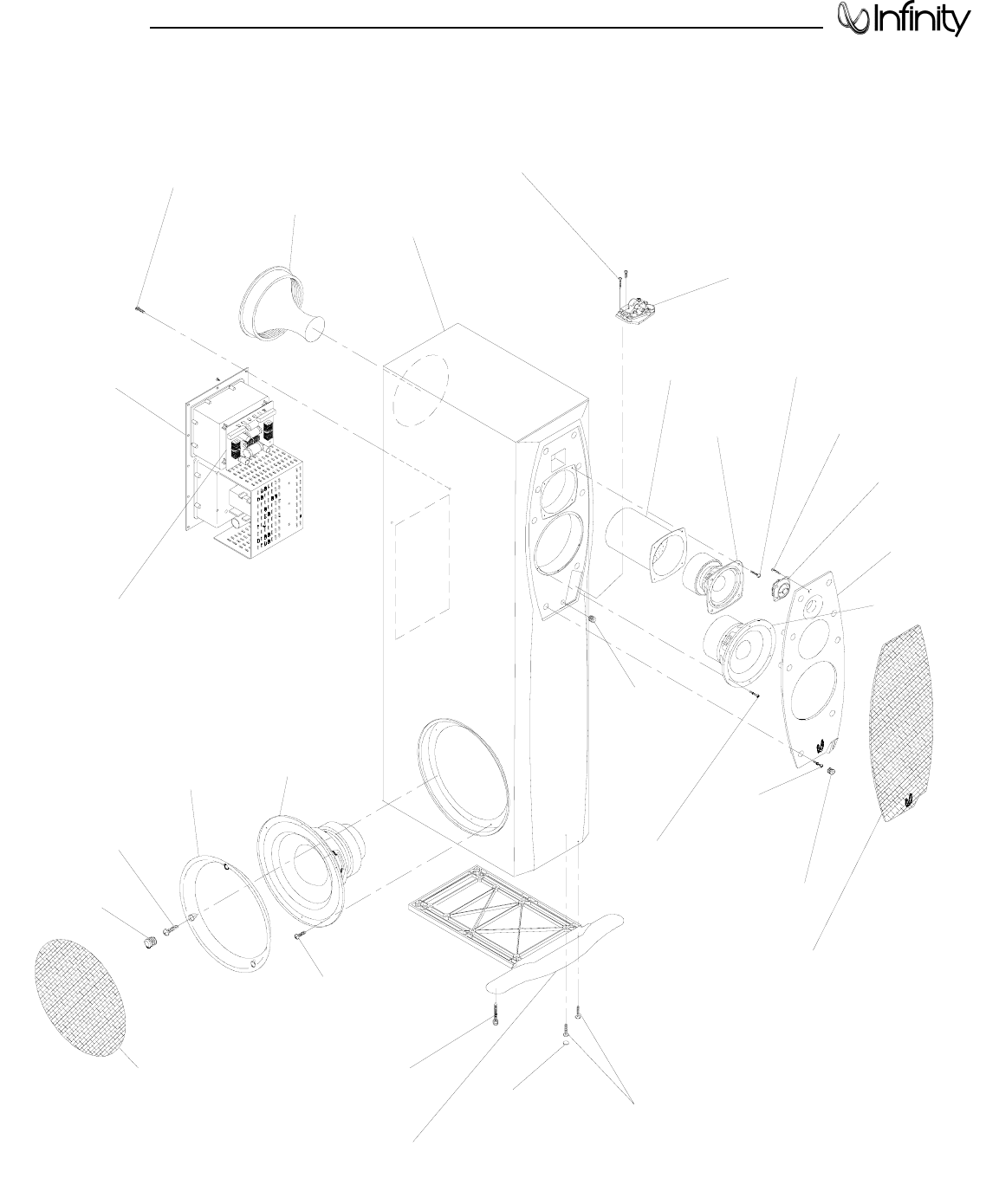
Mechanical Parts List
IL60 Complete Amplifier Ass’y N/A
Grille Set (one Upper and one Woofer):
Grille, Black, Left 336440-072
Grille, Black, Right 336440-071
Grille, Midnight Blue, Left 336440-052
Grille, Midnight Blue, Right 336440-051
Grille, Rich Burgundy, Left 336440-062
Grille, Rich Burgundy, Right 336440-061
Grille, Gray, Left 336440-042
Grille, Gray, Right 336440-041
Mid-Bass, 6-1/2” C.M.M.D., shielded, 4.5 ohms±10% 335741-001
Midrange, 4” C.M.M.D., shielded, 4.6 ohms±10% 335812-002
Woofer, 12”, C.M.M.D., shielded, 3.4 ohms±10% 336056-001
Tweeter, 1”, C.M.M.D., shielded, 3.5 ohms±10% 335225-002
Volume Control Assembly (Left) 336250-002
Volume Control Assembly (Right) 336250-001
Passive Crossover Network 336500-001
Port Tube 336799-001
Pedestal 336255-001
Cup, Grille, (12) 333249-003
Baffle, Front, Left 336442-002
Baffle, Front, Right 336442-001
Bump-On, Foot (8) 330104-001
Midrange Cup 335809-001
Trim Ring, Woofer 336259-001
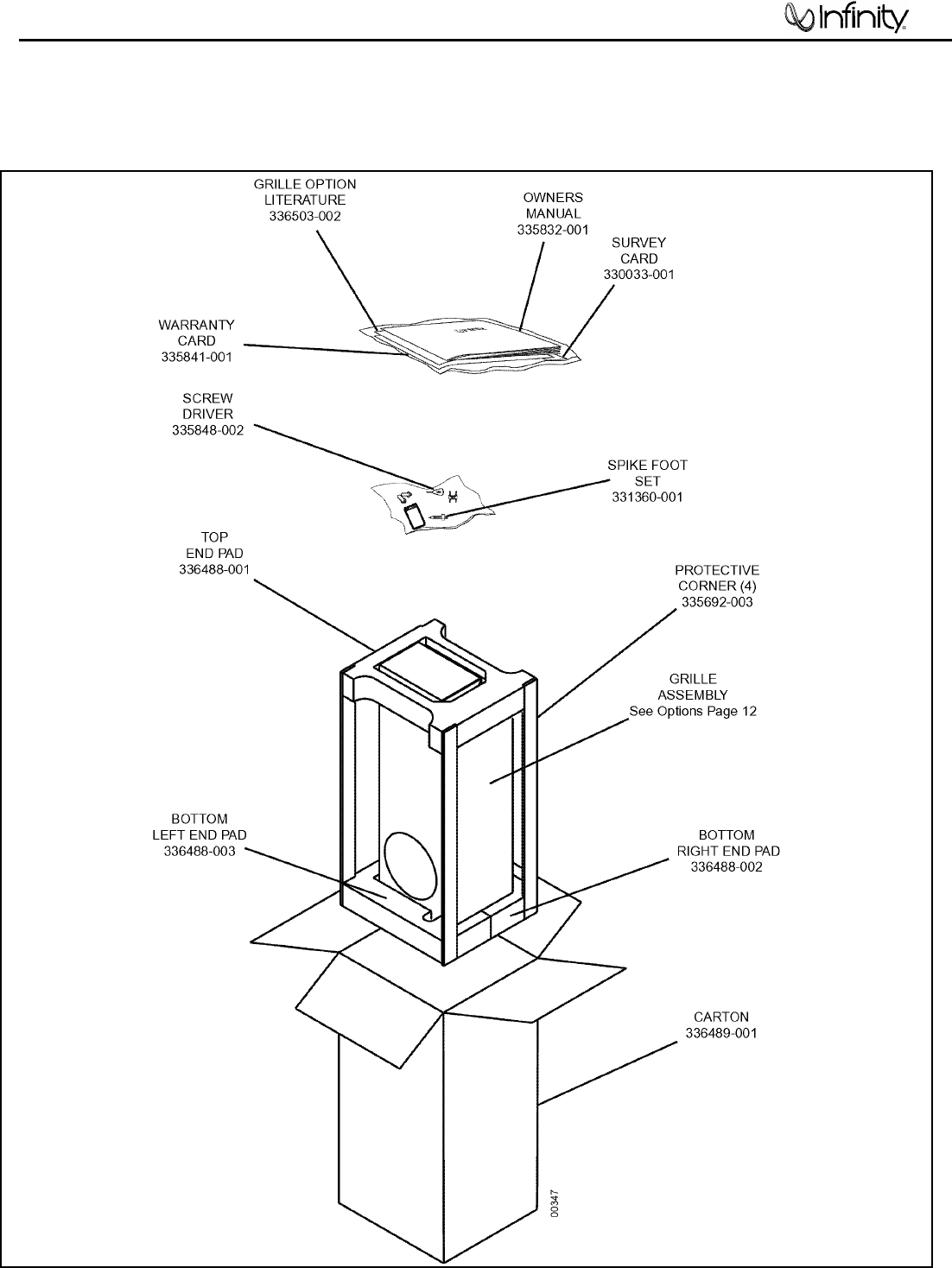
PACKAGING
Owners Manual, IL50,60 335832-001
Grille Option Literature 336503-002
Grille Assembly See Options Above
Pad, End, Bottom/L 336488-003
Pad, End, Bottom/R 336488-002
Pad, End, Top 336488-001
Protective Corners (4) 335692-003
Outer Carton 336489-001
Survey Card 330033-001
Warranty Card 335841-001
Spike Foot Set 331360-001
Power cord 120v US (15’) 336658-115
RABOS screwdriver w/bag 335848-002
IL60 L/R
13
GRILLE, BLACK, LEFT 336440-072
GRILLE, BLACK, RIGHT 336440-071
GRILLE, MIDNIGHT BLUE, LEFT 336440-052
GRILLE, MIDNIGHT BLUE, RIGHT 336440-051
GRILLE, RICH BURGUNDY, LEFT 336440-062
GRILLE, RICH BURGUNDY, RIGHT 336440-061
GRILLE, WARM PLATINUM, LEFT 336440-042
GRILLE, WARM PLATINUM, RIGHT 336440-041
GRILLE, WOOFER,
Part of Set - See
Upper Grille Options
GRILLE CUP, (3)
333249-003 GRILLE CUP, (8)
333249-003
GRILLE
CUP, (1)
333249-003
SCREW, (3)
#8 x 1" PPH, BLK
900101-016
SCREW, (3)
#8 x.75" PPH BLK
900101-012
SCREW, (12)
#8 x.75" PPH BLK
900101-012
SCREW, (4)
#8 x.75" PPH BLK
900101-012
SCREW, (6)
#6 x .75" PPH BLK
903401-012
SCREW, (4)
#4-24"x .375 PPH BLK
907801-006
SPIKE (2)
331360-001 BUMP-ON (8)
330104-001
PEDESTAL,
336255-001
PORT TUBE,
336799-001
(ROTATED)
VOLUME
CONTROL ASS'Y
w/CABLE,
336250-001,R
336250-002,L
AMPLIFIER,
NOT FOR SALE MIDRANGE
TRANSDUCER,
335812-002
MIDBASE
TRANSDUCER
335741-001
ISOLATION
CUP
335809-001
TWEETER,
335225-002
BAFFLE,
336442-001, R
336442-002, L
WOOFER,
336056-001
TRIM
RING,
336259-001
00415
SCREW, (8)
#6 x .75" PPH BLK
903401-012
SCREW, (4)
#6 x .75" PPH BLK
903401-012
SCREW, (10)
#8 x .75" PPH BLK
900101-012
CABINET
NOT FOR SALE
CROSSOVER
NETWORK
336500-001
Exploded View
IL60 L/R
14
LINEAR
BOARD
FEATURE
BOARD
RABOS
BOARD
POWER
SUPPLY
BOARD
NETWORK,
336500-001
RCA SINGLE
PC MT (2)
(JC0091)
SWITCH,
SPDT TOGGLE
(SR0007)
PAIR BINDING
POSTS GOLD
(JC0104)
FUSE HOLDER
PANEL MT SEALED
(FH0012)
FUSE, 4A 250V
1.25X.25 SLO-BLO
(FS0026)
AC (120V)
IEC SOCKET
(JC0129)
SWITCH,
ROCKER POWER
(SR0032)
FRONT VIEW
00420
EMI
BOARD
Exploded View of Amplifier
IL60 L/R
15
Service Tips
IL60 L/R
16
Test Set Up and Procedure
SYSTEM AURAL SWEEP TEST
Equipment needed:
• Function/signal generator/sweep generator
• Integrated Amplifier
• Multimeter
• Speaker cables
General Unit Function (UUT = Unit Under Test)
Switches on the amplifier faceplate:
Sub Input to “Line Level”
Low Pass Filter to OFF
Bass Optimization system to OFF
1. From the signal generator, connect one line level (RCA) cable to the IL60 Line Level Input jack on the UUT.
2. On the front of the unit, turn the LEVEL control full counterclockwise (1).
3. Turn on generator, adjust to 100mV, 40 Hz.
4. Plug in UUT; turn the power switch ON. LED should be Red. Turn LEVEL control full clockwise (10).
5. LED should now be Green; immediate bass response should be heard and felt from rear port tube opening.
6. Turn off generator, turn LEVEL control fully counterclockwise (1), disconnect RCA cable.
7. Connect one pair of speaker cables to Speaker Level input terminal on UUT. Cables should be connected to
an integrated amplifier fed by the signal generator.
8. Switch Sub Input on the amplifier faceplate to “Speaker”.
9. Turn on generator and adjust so that speaker level input at the amplifier is 1.5V, 50 Hz. Turn LEVEL control
full clockwise (10).
10. Green LED should light, immediate bass response should be heard and felt from the port tube opening.
Sweep Function
1. Follow steps 7-10 above, using a sweep generator as a signal source.
2. Sweep generator from 20Hz to 20kHz. Listen to the cabinet and drivers for any rattles, clicks, buzzes or any
other noises. If any unusual noises are heard, remove woofer and test.
Driver Function (Woofer)
1. Remove woofer from cabinet; detach + and - wire clips.
2. Check DC resistance of woofer; it should be 3.4 ohms ±10%.
3. Connect a pair of speaker cables to driver terminals. Cables should be connected to an integrated amplifier
fed by a signal generator. Turn on generator and adjust so that speaker level output is 5.0V.
4. Sweep generator from 20Hz to 1kHz. Listen to driver for any rubbing, buzzing, or other unusual noises.
SIGNAL
GENERATOR
AMPLIFIER
AC VOLT
METER (10V)
IL60
UNDER TEST
OUTPUT FROM GENERATOR/AMPLIFIER
O
+
®
00345
IL60 ADJUST BIAS PROCEDURE
(Mandatory when any output MOSFET transistors Q3,4,7,8 are replaced)
1. Amplifier should be unplugged and OFF.
2. Remove Amp assembly from cabinet; remove rear plastic cover if present. All wires exiting
the cover can remain connected unless they will prevent you from removing the amplifier or
accessing potentiometers on the Linear board PCB in the following steps.
3. Locate the Linear board assembly (PCB with the output transistors)
4. Adjust R11 and R27 fully Counter Clockwise. See diagram below.
5. Apply 120 VAC power to unit, Turn power switch ON.
6. Verify LED illuminates on the front gain control dial unless you have disconnected the plug.
7. Connect voltmeter set to DC millivolt range to twin pins on terminal J7, on Linear board
8. Verify initial voltage is less then 0.1 mV.
9. Adjust R11 Clockwise until voltmeter reads 0.3 mV + the initial current from step #8.
10. Adjust R27 Clockwise until voltmeter now reads 0.6 mV + the initial current from step #8.
11. Turn amplifier OFF. Disconnect AC power to unit.
12. Remove voltmeter from terminal J7.
13. Replace cover (if present), wires if disconnected, and replace amplifier back into cabinet.
IL60
17
Service Bulletin
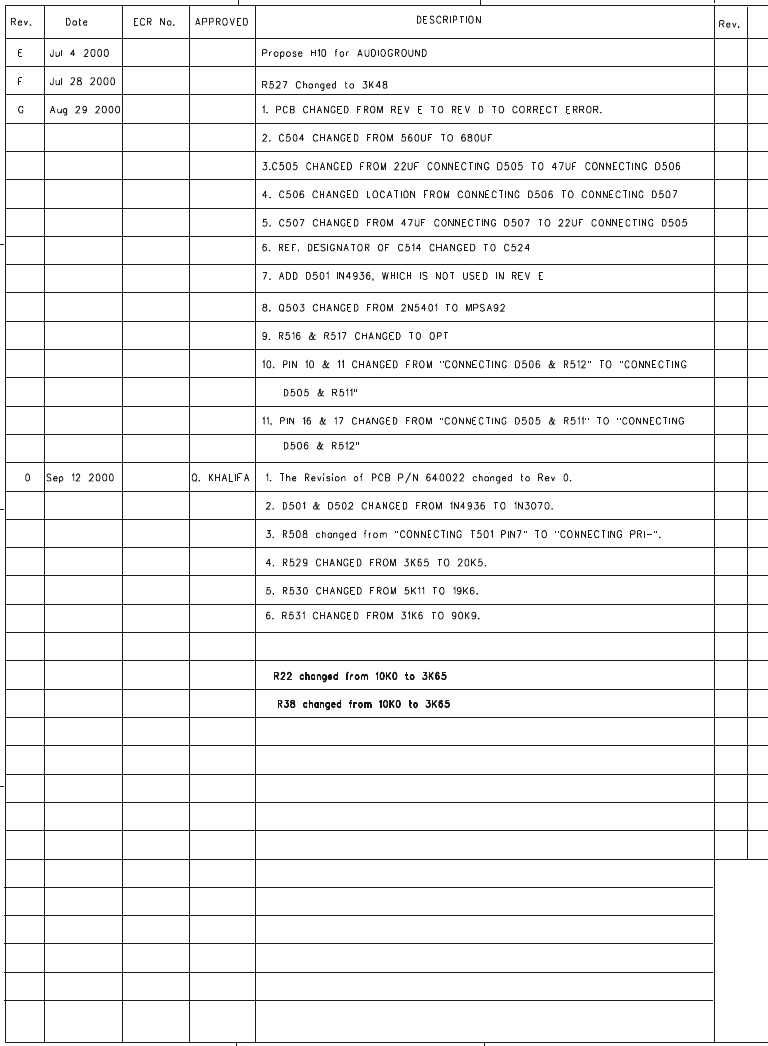
Service Bulletin INF2000-04 - December 2000 Warranty labor rate: MINOR repair
To: All Infinity Service Centers
Model: Interlude IL60
Subject: Air Leak or Buzzing from Front Baffle
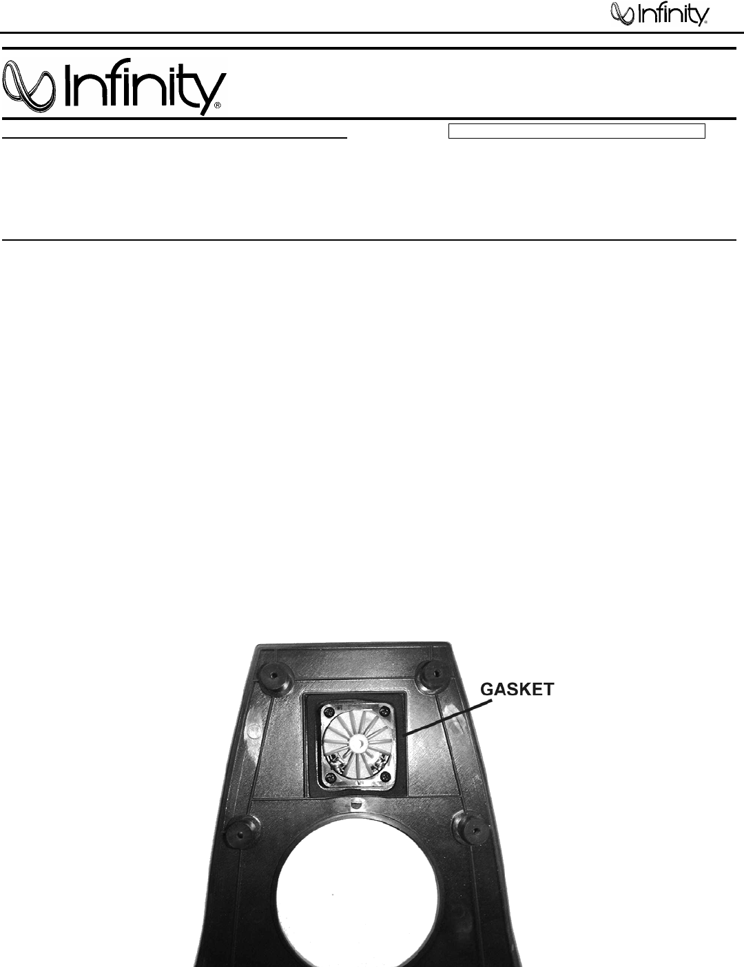
Some early versions of the Interlude IL60 loudspeaker may need an additonal gasket surrounding
the tweeter. The original gasket is located behind and is affixed to the front baffle.
In the event you receive an Interlude IL60 loudspeaker with the complaint: “There is buzzing
or an air leak coming from the upper part of the front baffle”, perform the following
modification:
1) Remove the loudspeaker grille.
2) Extract the (8) grille cups from their cavities with a needle-nosed pliers or similar tool.
3) Remove the (8) Phillips screws holding the front baffle to the cabinet
4) Remove the front baffle; unplug the two faston connections to the tweeter terminals.
5) Apply a new rectangular gasket, Infinity part# 336050-003, on top of the present gasket,
surrounding the tweeter. Final gasket(s) height should rise above the plastic “ledge” surrounding
the tweeter.
6) Plug both faston connections back on the tweeter terminals.
7) Replace the front baffle, Phillips screws, grille cups, and front grille.
IL60
18
Service Bulletin
Service Bulletin INF2001-04 Rev2 – May 2005 Warranty labor rate: MINOR repair
To: All Infinity Service Centers
Model: Interlude and Intermezzo IL50, IL60, IL100s, IL120s, IM1.2s, IM4.1t
Subject: No Output
In the event you receive an Interlude or Intermezzo loudspeaker with the complaint: “There is no
output, and the LED on the volume control does not light, red or green”, check the item listed below:
1) Check the line fuse to make sure it’s not damaged. Replace if necessary
IL50, IL100s 3A Infinity part# FS0022
IL60, IL120s 4A Infinity part# FS0026
IM1.2s, IM4.1t 6A Infinity part# FS0027
If the fuse is intact, or the unit still does not function, check the power supply portion of the amplifier
circuit, described below:
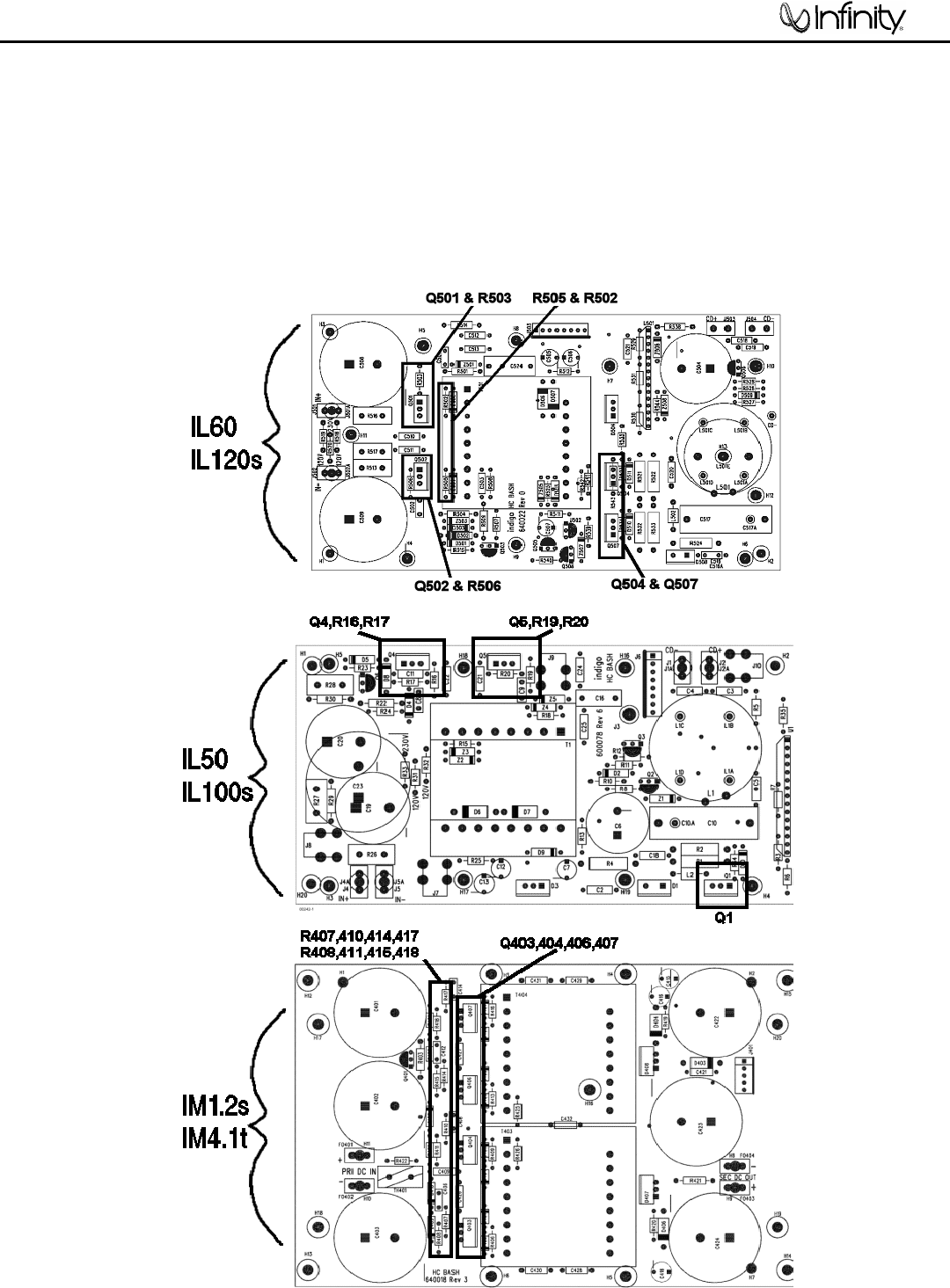
2) Refer to the Exploded view page for detailed instructions on amplifer removal from the enclosure.
3) Remove all connectors and screws necessary to detach the Power Supply PCB from the main chassis
heatsink. Squeeze the heads of the plastic standoffs with long-nosed pliers to detach the PCB from the
heatsink.
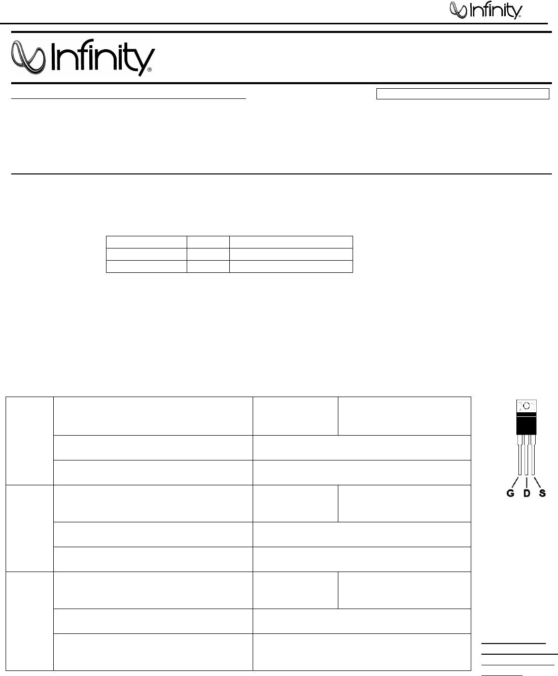
4) Refer to the illustration on page 2. Check the DC resistance of following parts, in circuit, with a DMM:
* The two
transistor leads
should be shorted
together before
these
measurements are
taken; the DMM
leads will “charge”
the circuit and the
value may change,
but should match
the values above.
Very low values
that do not change
indicate a shorted
MOSFET.
5) Replace any defective parts above that show measured values lower than normal.
6) Reconnect J505 or J6 multicolor ribbon cable connector; remount the Power supply PCB; reconnect
J501/502 or J4/J5 black/red Faston connectors.
7) All models except IM1.2S, IM4.1t: temporarily DO NOT connect the pair of black/red “CD±” leads on
the linear PCB). Isolate the ends so they are not touching each other, or any conductive material. (For
models IM1.2S, IM4.1t procedure is finished; replace amplifier).
IRF740 MOSFETS Q501, Q502
Infinity part# QM0055
D to S or S to D
G to S or S to G
D to G or G to D
Should measure >28K ohms*
Should measure >400 ohms
Should measure >28K ohms*
22 Ohm 0.6W Resistors R506, R503
Infinity part# RM0340
Should measure 22 ohms ±1%
IL120s
IL60 422 Ohm 1/4 watt Resistors R505, R502
Infinity part# RM0397
Should measure 422 ohms ±1%
IRF740 MOSFETS Q4, Q5
Infinity part# QM0055
D to S or S to D
G to S or S to G
D to G or G to D
Should measure >28K ohms*
Should measure >400 ohms
Should measure >28K ohms*
22 Ohm 0.6W Resistors R17, R20
Infinity part# RM0340
Should measure 22 ohms ±1%
IL50
IL100s 475 Ohm 1/4 watt Resistors R16, R19
Infinity part# RM0075
Should measure 475 ohms ±1%
IRF740 MOSFETS Q403,404,406,407
Infinity part# QM0055
D to S or S to D
G to S or S to G
D to G or G to D
Should measure >28K ohms*
Should measure >400 ohms
Should measure >28K ohms*
22 Ohm 0.6W Resistors R407,410,414,417
Infinity part# RM0340
Should measure 22 ohms ±1%
IM1.2s
IM4.1t
365 Ohm 1/4 watt Resistor
R408,411,415,418
Infinity part# RM0072
Should measure 365 ohms ±1%
IL60
19
8) Connect the subwoofer amplifier to an AC power source; turn the unit ON. Measure the DC voltage at
the “CD±” wires; it should be 10-20 volts.
9) If it is 25 volts or greater, turn the amplifier OFF, disconnect from the power source, and replace:
IL120S, IL60: Q504,Q507 IRF640 on the Power Supply PCB, Infinity part# QM0015.
IL50, IL100s: Q1 IRF540 on the Power Supply PCB, Infinity part# QM0020.
10) If the voltage is normal, turn the amplifier OFF, disconnect from the power source, and reconnect the
“CD±” leads.
11) Finish reassembling the amplifier, remount the heatsink, replace the amplifier in the cabinet and test
the subwoofer.
IL60
20

TECH TIPS
Troubleshooting tips and solutions to common service problems
For models: IL50, IL100s, MSW-1, IL60, IL120s, IM2.6, IM3.5c TIP# INFTT2003-03
Intermezzo, Interlude and Modulus MSW-1 Power Supply Repair
Recommended for instances where the PCB has been damaged, for the above models only:
1) Change all MOSFETS, even for one device failure.
2) Clean and repair the PC board if required (See Tech Tip HCG2002-01 - Damaged Printed Circuit
Boards).
3) Replace the Hybrid Bash Controller IC:
U1 in models: IL50,IL100s,MSW-1,IM2.6,IM3.5c
U501 in models: IL60, IL120s
Infinity part # HC1011
FAILURE TO FOLLOW THE INSTRUCTIONS ABOVE MAY RESULT IN UNIT FAILURE WHEN THE
AMPLIFIER IS POWERED UP
IL60
21
Packaging
IL60
22
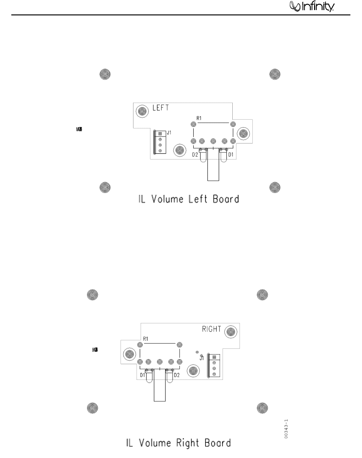
Volume Left/Right Boards
IL60
23
IL60 L/R
IL60
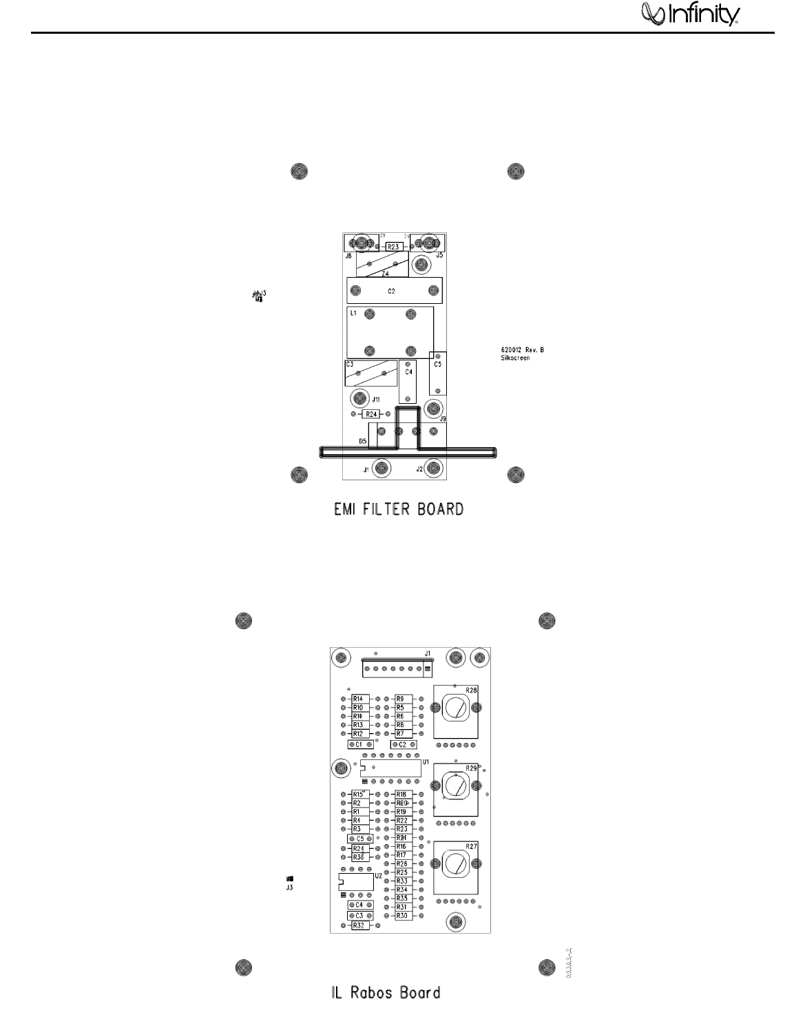
EMI FILTER/RABOS PCBs
24
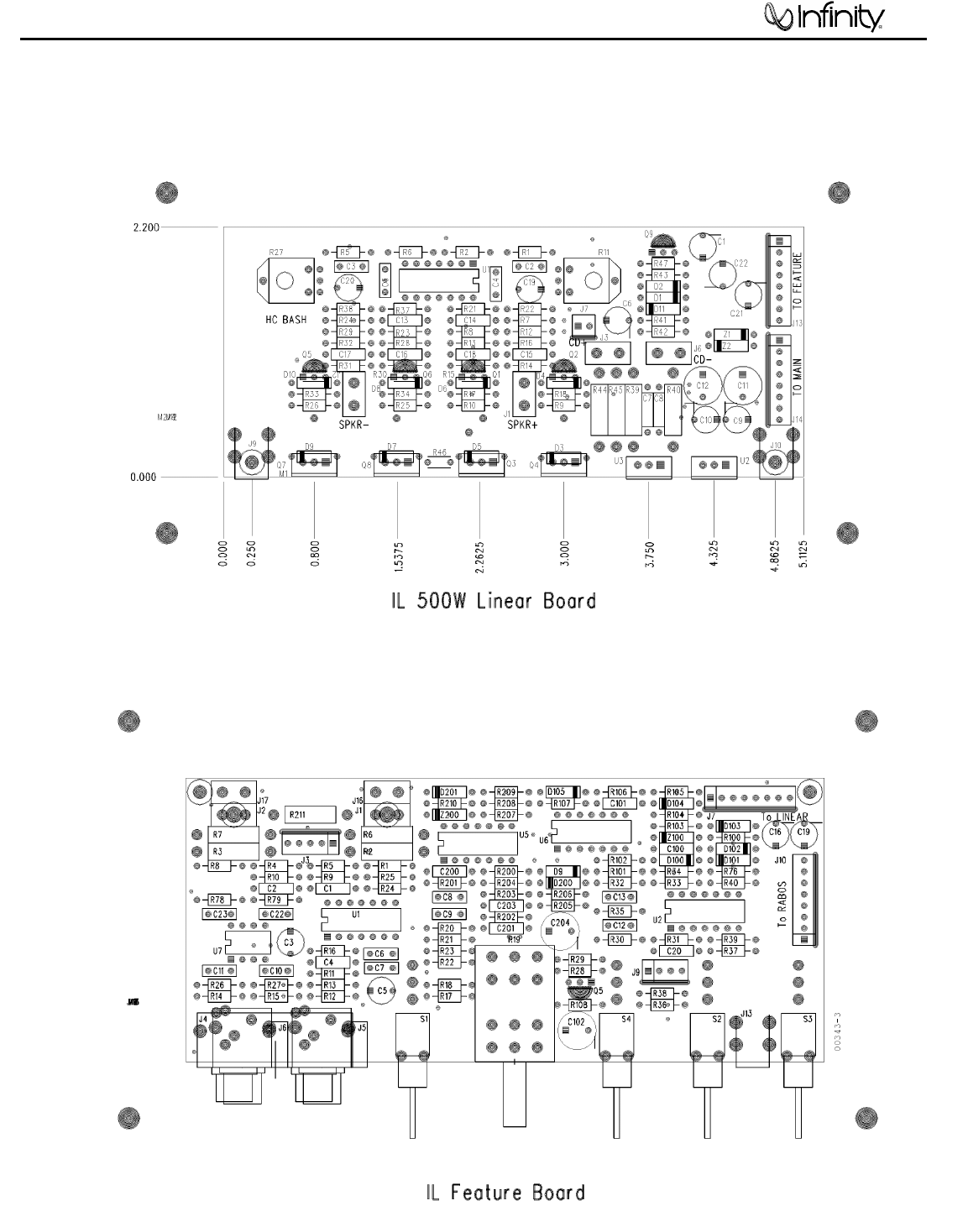
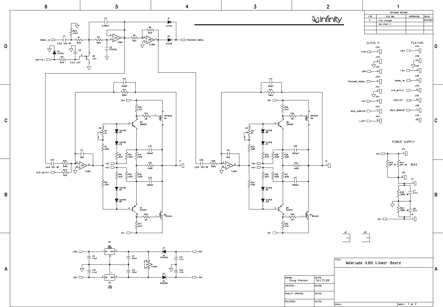
IL 500W Linear/Feature Boards
IL60
25

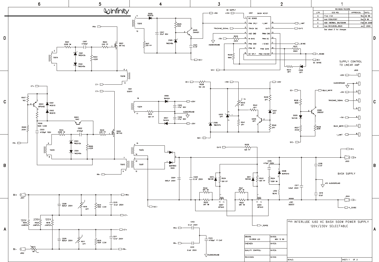
500W HC BASH Power Supply (120V/230V Selectable)
IL60
26

IL60 Electrical Parts List
Part# Reference Designator Qty Description
Feature PCB Assembly
SEMICONDUCTORS
DS0001 D9,D100,D101,D102,D103, 9 RECT, 100mA 75V SIGNAL 1N4148T
D104,D105,D200,D201
QM0035 Q5 1 JFET, N-CH J111 TO92 TR
UA0003 U5,U6 2 OPAMP, QUAD 14PIN DIL LM324N
UA0009 U1,U2 2 OPAMP, QUAD 14P DIL TL074/084
UA0010 U7 1 OPAMP, DUAL 8PIN DIL TL082
DZ0014 Z100 1 ZENER, 500MW 14V 5% 1N5244B
DZ0002 Z200 1 ZENER, 500mW 12V 5% 1N5242B
CAPACITORS
CC0020 C200 1 CAP, CA 470PF 100V 5%
CC0025 C203 1 CAP, CA 1000PF 100V 10%
CC0072 C1, C2, C4, C20, C100, C101 6 CAP, CA 100PF 100V 10%
CC0082 C201 1 CAP, CA .1UF 50V 20%
CE0013 C204 1 CAP, E 47UF 50V 20% 5MMLS
CE0101 C16, C19 2 CAP, E 4.7UF 50V 85D 5X11 5MML
CE0103 C102 1 CAP, E 100UF 35V 85DEG 5MMLS
CE0106 C5 1 CAP, E 22UF 35V BP 8X11 5MMLS
CE0108 C3 1 CAP, E 4.7UF 16V BIPOLAR 5X11
CF0045 C7, C9, C10, C11 4 CAP, F .1UF 63DC 5% 5MMLS
CF0055 C6, C8 2 CAP, F .22UF 63V 10% 5MMLS
CF0078 C12, C13 2 CAP, F .47UF 63V 10% 5MMLS
RESISTORS
RC0001 R211 1 RES, CF 1K0 1/2W 5%
RC0192 R3 1 RES, CF 2K00 1/2W 5%
RC0273 R19A, R19B, R19C, R19D, R20, R24, 10 RES, ZERO OHM 1/4W
R33, R36, R39, R79
RC0290 R206 1 RES, CF 9M1 1/4W 5%
RM0002 R12, R17, R22, R100, R101, R102, R208, R209 8 RES, MF 10K0 1/4W 1%
RM0003 R16, R210 2 RES, MF 15K0 1/4W 1%
RM0011 R1,R4,R103,R105,R201 5 RES, MF 100K 1/4W 1%
RM0012 R14,R30 2 RES, MF 100R 1/4W 1%
RM0016 R104 1 RES, MF 13K0 1/4W 1%
RM0020 R28,R29 2 RES, MF 1K40 1/4W 1%
RM0024 R207 1 RES, MF 2K21 1/4W 1%
RM0031 R204 1 RES, MF 3K32 1/4W 1%
RM0035 R200 1 RES, MF 4K75 1/4W 1%
RM0075 R205 1 RES, MF 475R 1/4W 1%
RM0085 R107 1 RES, MF 2K00 1/4W 1%
RM0097 R35 1 RES, MF 6K19 1/4W 1%
RM0106 R26 1 RES, MF 14K0 1/4W 1%
RM0120 R9,R10 2 RES, MF 30K1 1/4W 1%
RM0136 R202 1 RES, MF 150K 1/4W 1%
RM0156 R108 1 RES, MF 392K 1/4W 1%
RM0158 R27 1 RES, MF 28K0 1/4W 1%
RM0171 R31,R203 2 RES, MF 475K 1/4W 1%
RM0188 R106 1 RES, MF 499R 1/4W 1%
RM0191 R32 1 RES, MF 20K5 1/4W 1%
RM0263 R11 1 RES, MF 48K7 1/4W 1%
RM0361 R76 1 RES, MF 2K10 1/4W 1%
RM0402 R18,R23 2 RES, MF 11K5 1/4W 1%
RM0404 R2 1 RES, MF 54R9 1/4W 1%
MISCELLANEOUS
480113 J1 1 SUB, #18B 6 1/4 STRIP BOTH
480114 J2 1 SUB, #18R 6 1/4 STRIP BOTH
JC0091 J5, J6 2 CNCTR, RCA SINGLE PC MT
JH0006 J9 1 CNCTR, HEADER 4PIN .100CTR
JH0074 J7, J10 2 CNCTR, HEADER 8PIN LOCKING .1C
MT0003 J17 1 TERM, FASTON MALE PCMT 250X032
IL60
27

IL60 Electrical Parts List (Cont.)
Part# Reference Designator Qty Description
MT0036 J16 1 TERM, FASTON MALE PCMT 205X032
SR0007 S1,S3,S4 3 SWITCH, SPDT TOGGLE C/W CAP PC
PCB, RABOS Board
SEMICONDUCTORS
UA0009 U1 1 OPAMP, QUAD 14P DIL TL074/084
UA0010 U2 1 OPAMP, DUAL 8PIN DIL TL082
RESISTORS
RC0273 R30,R32,R33 3 RES, ZERO OHM 1/4W
RM0001 R24,R25 2 RES, MF 1K00 1/4W 1%
RM0002 R1,R2,R4,R9,R14,R15,R21,R23 8 RES, MF 10K0 1/4W 1%
RM0003 R8,R13 2 RES, MF 15K0 1/4W 1%
RM0012 R3 1 RES, MF 100R 1/4W 1%
RM0013 R34 1 RES, MF 11K0 1/4W 1%
RM0024 R22 1 RES, MF 2K21 1/4W 1%
RM0042 R26 1 RES, MF 681R 1/4W 1%
RM0080 R5,R10 2 RES, MF 825R 1/4W 1%
RM0260 R36 1 RES, MF 1M0 1/4W 1%
RM0271 R19 1 RES, MF 110K 1/4W 1%
RM0281 R7,R12 2 RES, MF 6K04 1/4W 1
RM0315 R17 1 RES, MF 2K67 1/4W 1%
RM0369 R6,R11 2 RES, MF 340R 1/4W 1%
RM0370 R18 1 RES, MF 9K31 1/4W 1%
RM0377 R16 1 RES, MF 3K57 1/4W 1%
RM0378 R20 1 RES, MF 549R 1/4W 1%
RP0087 R27,R29 2 POT, A10K DUAL 12MM HOR SEL
RP0088 R28 1 POT, C10K DUAL 12MM HOR SEL
DNI R31, R35 2 Do Not Insert
CAPACITORS
DNI C3, C4 2 Do Not Insert
CF0045 C1,C2,C5 3 CAP, F .1UF 63DC 5% 5MMLS
MISCELLANEOUS
JH0074 J1 1 CNCTR, HEADER 8PIN LOCKING .1C
PCB, Linear Board
SEMICONDUCTORS
DS0001 D1-11 11 RECT, 100mA 75V SIGNAL 1N4148T
QB0017 Q2, Q6 2 TRANS, NPN 150V 0.6A 2N5551TR
QB0018 Q1, Q5 2 TRANS, PNP 150V 0.6A 2N5401TR
QM0015 Q3, Q7 2 MOSFET, IRF640 T0220AB
QM0034 Q4, Q8 2 MOSFET, IRF9540 T0220AB
QM0054 Q9 1 JFET, N-CH J113 T092
UA0009 U1 1 OPAMP, QUAD 14P DIL TL074/084
UV0015 U2 1 VREG, +18v 500MA LM7818CT
UV0016 U3 1 VREG, -18V 500MA LM7918CT
DZ0011 Z1, Z2 2 ZENER, 500MW 3V 5% 1N5225B
RESISTORS
RM0001 R12-15, R28-31 8 RES, MF 1K00 1/4W 1%
RM0002 R1, R2, R5, R6 4 RES, MF 10K0 1/4W 1%
RM0021 R7, R8, R23, R24 4 RES, MF 1K82 1/4W 1%
RM0024 R17, R18, R33, R34 4 RES, MF 2K21 1/4W 1%
RM0029 R9, R10, R25, R26 4 RES, MF 3K01 1/4W 1%
RM0035 R41, R42 2 RES, MF 4K75 1/4W 1%
RM0039 R47 1 RES, MF 5K11 1/4W 1%
RM0091 R22, R38 2 RES, MF 3K65 1/4W 1%
RM0170 R21, R37 2 RES, MF 59K 1/4W 1%
RM0180 R16, R32 2 RES, MF 4K99 1/4W 1%
RP0059 R11, R27 2 POT, 2K 8MM TOP ADJ/COVER
IL60
28

IL60 Electrical Parts List (Cont.)
Part# Reference Designator Qty Description
RW0022 R44, R45 2 RES, WW 0R1 2W 5%
RX0055 R39, R40 2 RES, MO 470R 2W 5%
CAPACITORS
CC0025 C15-18 4 CAP, CA 1000PF 100V 10%
CC0080 C13, C14 2 CAP, CA 220P 100V 10%
CC0082 C7, C8 2 CAP, CA .1UF 50V 20%
CC0097 C4, C5 2 CAP, C 10P 50V 10
CE0003 C6 1 CAP, E 2.2UF 50V 20% 105C
CE0013 C9, C10, C21, C22 4 CAP, E 47UF 50V 20% 5MMLS
CE0085 C19, C20 2 CAP, E 22UF 16V BP 6X11 5MMLS
CE0103 C11-12 2 CAP, E 100UF 35V 85DEG 5MMLS
CE0116 C1 1 CAP, E 2.2UF 50V BP 6X11 5MMLS
CF0125 C3 1 CAP, F .068UF 100V 5% 5MMLS
CF0128 C2 1 CAP, F .033UF 100V 5% 5MMLS
MISCELLANEOUS
KS0019 R46 1 THERMISTOR, PTH9L04BD22TS2F510
JH0016 J7 1 CNCTR, HEADER 2PIN .100CTR
JH0074 J13, J14 2 CNCTR, HEADER 8PIN LOCKING .1C
MM0025 J9, J10 2 MISC, PC MT SCREW TERM 6-32
MT0003 J1 1 TERM, FASTON MALEPCMT 250X032
MT0023 J3, J6 2 TERM, FASTON MALEPCMT 187X032
MT0036 J2 1 TERM, FASTON MALEPCMT 205X032
TS0016 6 TUBING, #5 BLACK CUT TO .3
810056 6 MET, HTSNK CLIP .9X.5X.2 FET Used on Q3, Q4, Q7,
Q8, U2 & U3
MS0005 2 SILPAD, .009 .3C/W TO3P used with regulators U2 & U3
MS0017 4 MISC, CERAMIC PLATE TO-220 Oxide used with FETs
PCB, Power Supply 500W 230V/120V
SEMICONDUCTORS
DR0077 D506, D507 2 RECT, 1A 100V FAST REC 1N4934
DS0001 D509, D510, D511 3 RECT, 100mA 75V SIGNAL 1N4148T
DS0002 D501, D502, D505 3 RECT, 100MA 200V SIGNAL 1N3070
DD0003 D503 1 RECT, 1A2 60V DIAC
DR0076 D504 1 RECT, 16A 400V ULTRA MUR1640CT
DR0087 D508 1 RECT, 15A 200V ULTRA MUR1540
QB0002 Q505 1 TRANS, NPN 40V .6A TO92 2N4401
QB0014 Q503 1 TRANS, PNP TO92 MPSA92TR
QB0017 Q506 1 TRANS, NPN 150V 0.6A 2N5551
QM0015 Q504, Q507 2 MOSFET, IRF640 TO220AB
QM0055 Q501, Q502 2 MOSFET, IRF740 TO220AB
HC1011 U501 1 HYBRID, THK FILM HC BUCK CNTR
DZ0002 Z501, Z503 2 ZENER, 500mW 12V 5% 1N5242B
DZ0004 Z505 1 ZENER, 500mW 18V 5% 1N5248B
DZ0021 Z502, Z504 2 ZENER, 500MW 15V 5% 1N5245B
DZ0038 Z506 1 ZENER, 500MW 33V 5% 1N5257B
RESISTORS
RC0082 R509 1 RES, CF 100K 1/2W 5%
RC0136 R515 1 RES, CF 160K 1/4W 5%
RC0273 R518, R519 2 RES, ZERO OHM 1/4W
RM0001 R507 1 RES, MF 1K00 1/4W 1%
RM0002 R525 1 RES, MF 10K0 1/4W 1%
RM0050 R531 1 RES, MF 90K9 1/4W 1%
RM0070 R528 1 RES, MF 301R 1/4W 1%
RM0191 R529 1 RES, MF 20K5 1/4W 1%
RM0198 R508 1 RES, MF 205K 1/4W 1%
RM0260 R526 1 RES, MF 1M0 1/4W 1%
RM0337 R530 1 RES, MF 19K6 1/4W 1%
RM0339 R511, R512, R523, R534, R535 5 RES, MF 10R 0.6W 1% FLAMEPROOF
IL60
29

IL60 Electrical Parts List (Cont.)
Part# Reference Designator Qty Description
RM0340 R503, R506 2 RES, MF 22R 1/4W 1% FLAMEPROOF
RM0397 R502, R505 2 RES, MF 422R 1/4W 1%
RM0399 R527 1 RES, MF 3K48 1/4W 1%
RW0022 R521, R522, R532, R533 4 RES, WW 0R1 2W 5%
RX0046 R514 1 RES, MO 47K 1W 5%
RX0048 R501, R504 2 RES, MO 330R 1W 5%
RX0072 R524 1 RES, MO 100R 1W 5
RX0106 R538 1 RES, MO 15K 2W 5%
CAPACITORS
CE0013 C505, C506 2 CAP, E 47UF 50V 20%
CE0098 C507 1 CAP, E 22UF 50V 20% 5X11 .2LS
CF0019 C501, C502 2 CAP, F 4700PF 100V 5% 5MMLS
CC0040 C503 1 CAP, CA 4700PF 100V 10%
CC0059 C518, C519 2 CAP, CA .1UF 100V 20%
CC0082 C521 1 CAP, CA .1UF 50V 20%
CC0021 C516 1 CAP, C 470PF 1KV 10%
CC0130 C524 1 CAP, CY1 4700PF 250V 20% 10MML
CE0040 C504 1 CAP, E 680UF 200V 30X35 85DEG
CE0136 C508, C509 2 CAP, E 820UF 200V 20% 30X35
CF0050 C510, C511, C512, C513, C520 5 CAP, F .1UF 250V 10%
CF0146 C517 1 CAP, F 6.8UF 250V 10% 27MMLS
MISCELLANEOUS
KS0021 R513 1 SURGISTOR, 4R 8A 70J SL154R008
BF0007 L502 1 BEAD, FERRITE
500111 T501 1 XFMR, ETD44
540131 L501 1 IND, 25UH UPRIGHT AIR COIL
TS0016 HtSkTube 6 TUBING, #5 BLACK CUT TO .3 Used on D504, D508,
Q501, Q502, Q504 & Q507
HS0054 4 SCREW, #4 SELF TAP 1/2 PAN PHI USED ON H4, H5,
H6, H7
HS0089 4 SCREW, #4-40X1/2 PAN PHIL ZNP USED ON
HEATSINK
HW0030 4 WASHER, FLAT #8 NYLON USED WITH HS0089 ON
HEATSINK
JH0074 J505 1 CNCTR, HEADER 8PIN LOCKING .1C
MT0023 J501, J502, J503, J504 4 TERM, FASTON MALE PCMT 187X032
810066 Clip 6 MET, HTSNK CLIP HPS SERIES Used on Q501, Q502,
Q504, Q507, D504 & D508
810105 Heatsink 1 Lance and Form Heatsink Primary
810106 Heatsink 1 Lance and Form Heatsink Secondary There should be a
piece of tape in between the heatsink and the PCB.
MS0017 Ceramic 2 MISC, CERAMIC PLATE TO-220 USED ON Q504, Q507
Q508 1 Do not insert
R516, R517, R539, R540, R541, R542, R543, R544 8 Do not insert
U502 1 Do not insert
Z507, Z508 2 Do not insert
PCB, EMI Filter board
SEMICONDUCTORS
DB0009 D5 1 RECT, 6A 400V BRIDGE
RESISTORS
RC0004 R23 1 RES, CF 1M0 1/4W 5%
CAPACITORS
CC0130 C3 1 CAP, CY1 4700PF 250V 20% 10MML
CF0050 C4, C5 2 CAP, F .1UF 250V 10% 10MMLS
CF0057 C2 1 CAP, FX .22UF 250V 10%
IL60
30

IL60 Electrical Parts List (Cont.)
Part# Reference Designator Qty Description
MISCELLANEOUS
KV0001 Z4 1 VARISTOR, 275V 100J .6W
MT0023 J5, J6 1 TERM, FASTON MALE PCMT 187X032
480097 J1 1 SUB, #18B 9 187X032/1/4STRP
480090 J2 1 SUB, #18R 9 187X032/1/4STRP
540124 L1 1 IND, CM CHOKE YT7271
810088 1 MET, Heatsink 1x2 Bridge
HN0006 1 NUT, HEX KEP #6-32 ZNP Used with screw HS0066
HS0066 1 SCREW, #6-32X1/2 PAN PHIL BLK Used on the bridge
and heatsink
PCB, VOLUME-LED INTERLUDE LEFT
DL0014 D1,D2 2 LED, 3MM BICOLOR RED/GR
RP0099 R1 1 POT, C10K SINGLE/BRKT D SHAFT
JH0006 J1 1 CNCTR, HEADER 4PIN .100CTR
HS0078 3 SCREW, #4-24X1/2 HL PP BLK USED ON 610043
HW0038 1 WASHER, FLAT .195ID .437OD RB AT PLASTIC
HOUSING FOR CABLE.
1 INTERLUDE VOL-LED MTG PLT LEFT
JC0169A 1 CNCTR, FEM-MA HARNESS 4PSH 15 USED ON
LOCATION J1
MM0065 1 MISC, VOL GASKET L INTERLUDE
RP0104 1 POT, KNOB INTERLUDE LEVEL L
PCB, VOLUME-LED RIGHT
DL0014 D1,D2 2 LED, 3MM BICOLOR RED/GR
RP0097 R1 1 POT, A10K SINGLE/BRKT D SHAFT
JH0006 J1 1 CNCTR, HEADER 4PIN .100CTR
HS0078 3 SCREW, #4-24X1/2 HL PP BLK USED ON 610044
HW0038 1 WASHER, FLAT .195ID .437OD RB AT PLASTIC
HOUSING FOR CABLE.
INTERLUDE CUP R 1 INTERLUDE VOL-LED MTG PLT RIGH
JC0169A 1 CNCTR, FEM-MA HARNESS 4PSH 15 USED ON
LOCATION J1
MM0066 1 MISC, VOL GASKET R INTERLUDE
RP0103 1 POT, KNOB INTERLUDE LEVEL R
MISCELLANEOUS
480033 3 SUB, #18R 4 187X032/187X032 1 PCS FOR IEC L TO
FUSE; 1 PCS FOR FUSE TO SWITCH; 1 PCS FOR
SWITCH TO EMI
480048 1 SUB, #18B 9 187X032/187X032 Power Supply CD- TO
LINEAR CD-
480073 1 SUB, #18R 9 187X032/187X032 Power Supply CD+ TO
LINEAR CD+
480083 2 SUB, #18B 4 187X032/187X032 1 for IEC TO SWITCH; 1
FOR SWITCH TO EMI
480091 1 SUB, #18R 7 187X032/187X032 DC+ TO POWER
SUPPLY
480119 1 SUB, #16B 20 205X032/205X032 XOVER - WIRE;
480120 1 SUB, #16R 20 250X032/250X032 XOVER + WIRE;
480121 1 SUB, #16B 30 205X032/205X032 SPEAKER - WIRE;
480122 1 SUB, #16R 30 250X032/250X032 SPEAKER + WIRE;
480130 1 SUB, #18B 7 187X032/187X032 DC- TO POWER
SUPPLY
810066 6 MET, HTSNK CLIP HPS SERIES USED ON D4, D8, Q1,
Q2, Q4 & Q7
810088 1 MET, HTSNK 1X2 BRIDGE REV 2; USED WITH THE
BRIDGE
810105 1 MET, HTSNK PRI 3FET IL120
810106 1 MET, HTSNK SEC 3FET IL120
810107 1 IL60/120 SHIELD
810108 1 IL60/120 POWER BRACKET
IL60
31

IL60 Electrical Parts List (Cont.)
Part# Reference Designator Qty Description
930054 1 CUP, PCBA BUCKET C/W GASKET FEATURE BOARD
BOX
930055 1 CUP, AMP BUCKET AC IN W/GASKET AC BOX
FH0012 1 FUSE, HOLDER PANEL MT SEALED
FS0026 1 FUSE, 4A 250V 1.25X.25 GLASS
HN0006 1 NUT, HEX KEP #6-32 ZNP USED WITH THE BRIDGE
HN0015 4 NUT, HEX KEP #8-32 ZNP USED WITH HS0057
HS0004 4 SCREW, #6-32X1/4 PAN PHIL ZNP 1PER USED ON
MZ0040; 1PER USED ON standoff P/N MZ0045; 2PER
USED ON MM0025 for Linear board
HS0041 7 SCREW, #4-3/8 TYPE A PP BLK 2 USED ON EMI
BOARD; 5 USED ON POWER SUPPLY BOARD
HS0057 4 SCREW, #8-32X1/2 PAN PHIL BLK MOUNT BRACKET
TO PANEL
HS0060 3 SCREW, #6-32X3/8 PAN PHIL BLK MOUNT SHIELD TO
BRACKET
HS0062 6 SCREW, #6-1/2 TYPE B PP BLK USED ON FETS
HS0065 3 SCREW, #6-32X1/4 PAN PHIL BLK 1 USED ON MZ0025
for Feature Board, 1 used on MZ0040, 1 used on standoff
P/N NEW
HS0066 1 SCREW, #6-32X1/2 PAN PHIL BLK USED WITH THE
BRIDGE
HS0067 26 SCREW, #6-3/8 TYPE A PP BLK 8 USED WITH 930054;
6 USED WITH 930055; 6pcs used on MZ0030; 3pcs used
on MZ0040; 3 pcs used on MM0025
HS0078 6 SCREW, #4-24X1/2 HL PP BLK 2PER USED ON
BINDING POSTS; 2PER USED ON RCA’S; 2PER USED
ON RABOS STANDOFF
HS0089 4 SCREW, #4-40X1/2 PAN PHIL ZNP TO CONNCT THE
HEATSINKS
IL60 PANEL 1 INTERLUDE IL60 PANEL COMPLETE
JC0071 1 CNCTR, FEM-FEM HARNESS 8PIN 9 USED ON THE
RABOS BOARD TO FEATURE BOARD
JC0104 1 CNCTR, 2PIN BP GOLD C/W TERM
JC0129 1 CNCTR, AC IEC SOCKET .250 2PIN
JC0163A 1 CNCTR, FEM-MAL HARNESS 8P 10 J7 ON THE
FEATURE TO J13 ON LINEAR BOARD
JC0163B 1 CNCTR, FEM-FEM HARNESS 8P 10 J7 ON THE
FEATURE TO J13 ON LINEAR BOARD
JC0165 1 CNCTR, FEM-FEM HARNESS 8P 12 Power supply to
Linear
JC0169C 1 CNCTR, FEM-FEM HARNESS 4PS 28 USED ON J9;
MM0069 3 MISC, RUBBER GROMMET IL50/100
MM0076 2 MISC, PANEL GASKET, IL60/IL120
MS0005 7 SILPAD, .009 .3C/W TO3P 3PER USED ON MAIN
BOARD; 4PER USED ON THE LINEAR BOARD;
MZ0003 1 STANDOFF, 6-32 3/8 ROUND AL USED ON AC FILTER
PCB
MZ0030 2 STANDOFF, 3/8 NYLON 2 PER USED ON AC FILTER
BOARD
MZ0040 2 STANDOFF, 30MM NYLON USED ON THE RABOS
BOARD
MZ0045 1 STANDOFF, 6-32X 1-3/16 HEX AL USED WITH THE
RABOS BOARD
SR0032 1 SWITCH, ROCKER TV5 ON THE FRONT PANEL
IL60
32
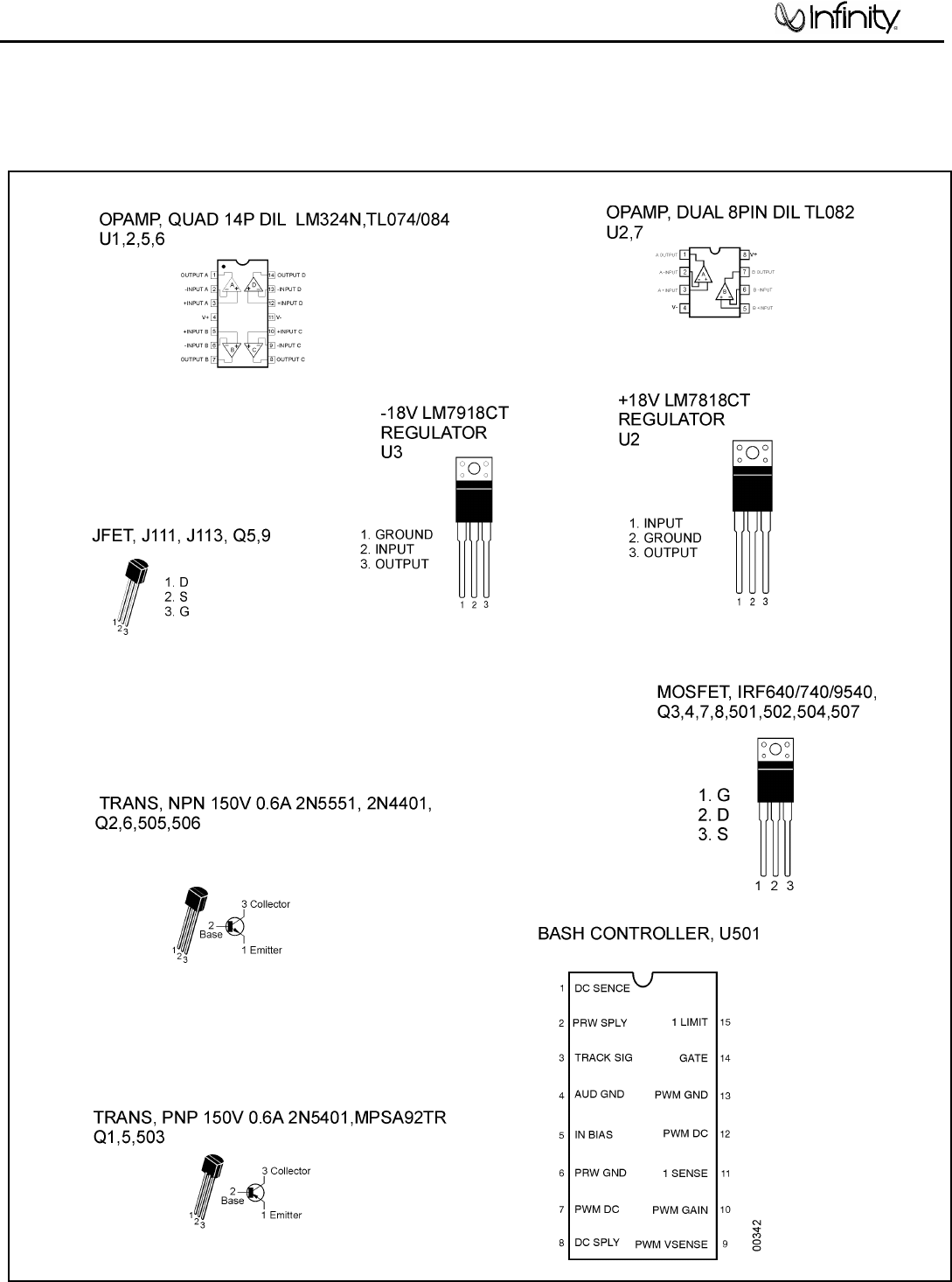
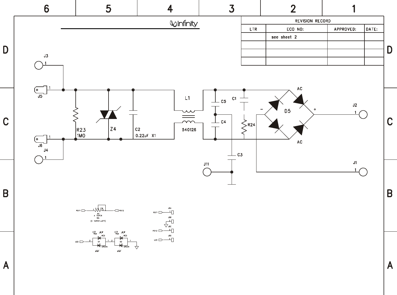
Integrated Circuit Diagrams
IL60
33
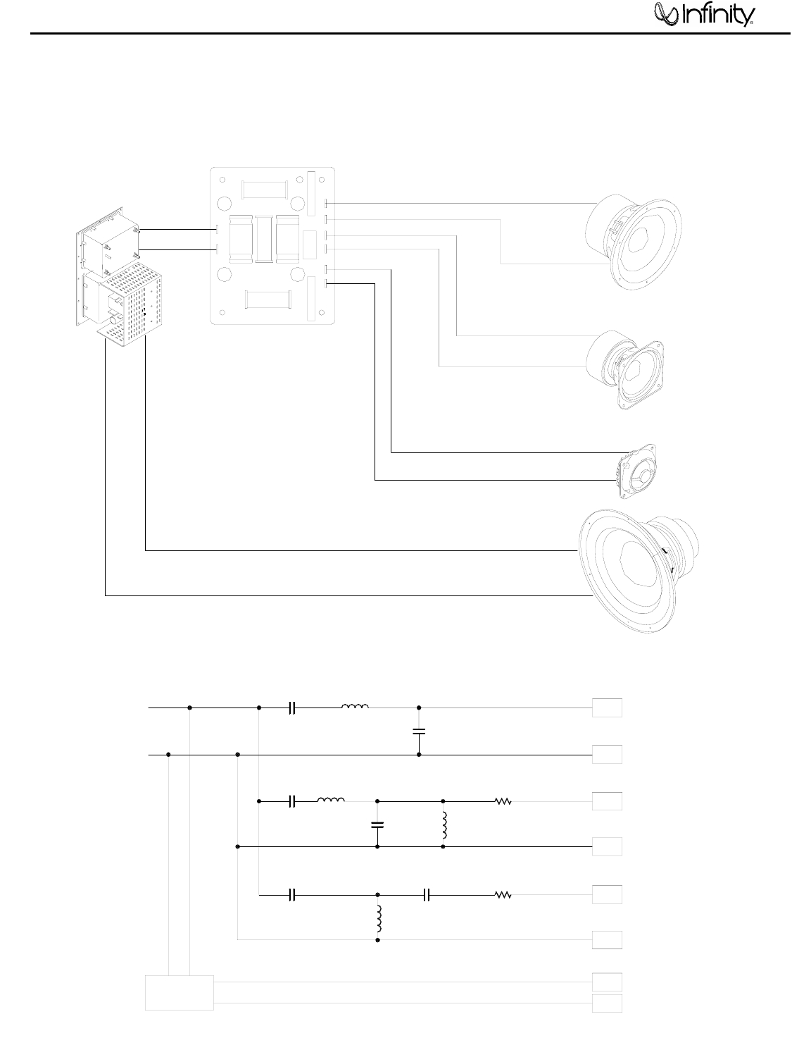
Wiring Diagram/Crossover Network
+ INPUT
- INPUT
C1
470 mF
100V L1
2.4 mH
C2
80 mF
100V
GRN
GRN/BLK
250 +MB
205 -MB
C3
14 mF
100V L2
0.75 mH
C4
8 mF
100V
L3
1.5 mH
R1
3.3 ohms
10W
+MR
250
WHT
WHT/BLK -MR
205
C5
2 mF
100V
L4
0.18 mH
C6
14 mF
100V
R2
1.8 ohms
10W YEL +HF
187
YEL/BLK -HF
110
AMPLIFIER BLK
RED .250 +LF
.205 -LF
W- W+ M- M+ Y-
T+
IN+ IN-
GRN
GRN/BLK -
+
WHT/BLK
WHT
-
+
YEL/BLK -
YEL +
MIDBASS
TRANSDUCER
335741-001
WOOFER
336056-001
TWEETER
335225-002
MIDRANGE
TRANSDUCER
335812-002
AMPLIFIER
NETWORK
336500-001
CROSSOVER NETWORK
SCHEMATIC
WIRING DIAGRAM
BLK -
RED +
00419
IL60
34
35
IL60
500W EMI/Volume PCB's
36
IL60
37
IL60
IL60
38
IL60
39
IL60
40
41
