Infinity Speaker Tss Sub500 Users Manual 500 (230) OM
TSS-500 Infinity TSS-50 sm
TSS-SUB500 to the manual a1ab2ac1-5f4d-451a-94a9-5a38081c7b1a
2015-01-23
: Infinity Infinity-Speaker-Tss-Sub500-Users-Manual-342651 infinity-speaker-tss-sub500-users-manual-342651 infinity pdf
Open the PDF directly: View PDF ![]() .
.
Page Count: 27
TSS-Sub500
(TSS-500 SYSTEM)
SERVICE MANUAL
Infinity Systems Incorporated
250 Crossways Park Dr.
Woodbury, New York 11797 Rev0 6/2006

Note: The TSS-Sub500 is part of the TSS-500 system
Satellite loudspeakers:
(Charcoal) order Infinity part# TSS-SAT500CHR
(Platinum) order Infinity part# TSS-SAT500PLT
Center channel: Call Infinity Systems parts department
(Charcoal) (Platinum)
CONTENTS
BASIC SPECIFICATIONS . . . . . . . . . ………………….………….... .. . . . . . 1
PACKAGING/ACCESSORIES. . . . . . . . . . . . . . . . . .………. . .. .. ... . . . . . 2
DETAILED SPECIFICATIONS . . . . . . . . . . . . . . . . . .………. . .. .. .. . . . . . 3
CONTROLS. ………………….. .. . …………………………………………….. 5
CONNECTIONS . . . . . . . . . . . ……….………………………………..…. . . . 6
OPERATION……. . . . . .. . . . . . . . .. .. . . . .. .. . . . . ….……… . . ... . . . . . . .7
EXPLODED VIEW-MECHANICAL PARTS LIST….… . ………………………..8
TEST SET-UP/PROCEDURE. . . . . . . . . . . . . . . . . .………. . .. .. .…. . . . . . 9
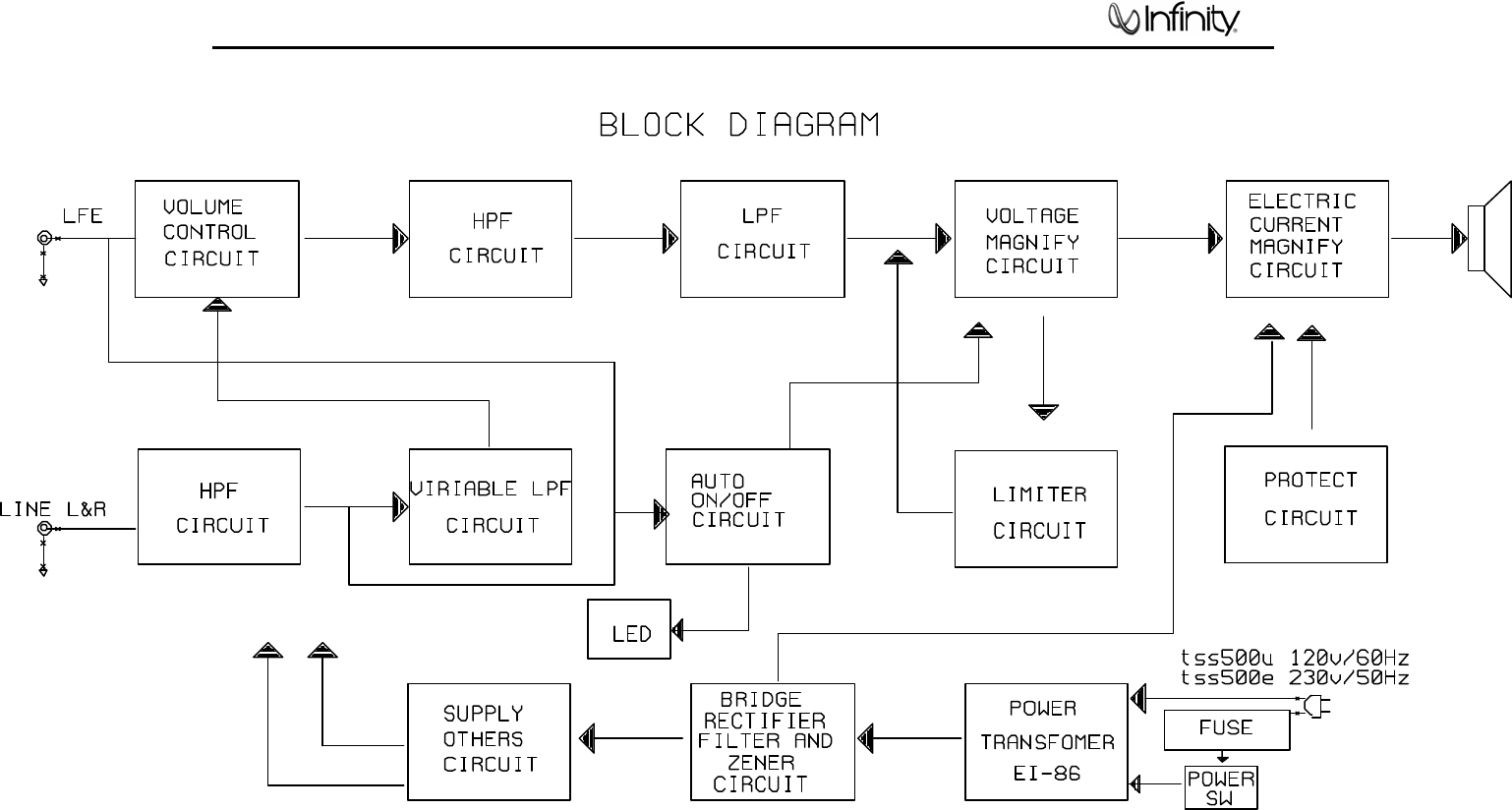
BLOCK DIAGRAM. . . . ………………... ………………………….... . . .. . … . 10
TROUBLESHOOTING FLOW CHART….… . ………………….………………11
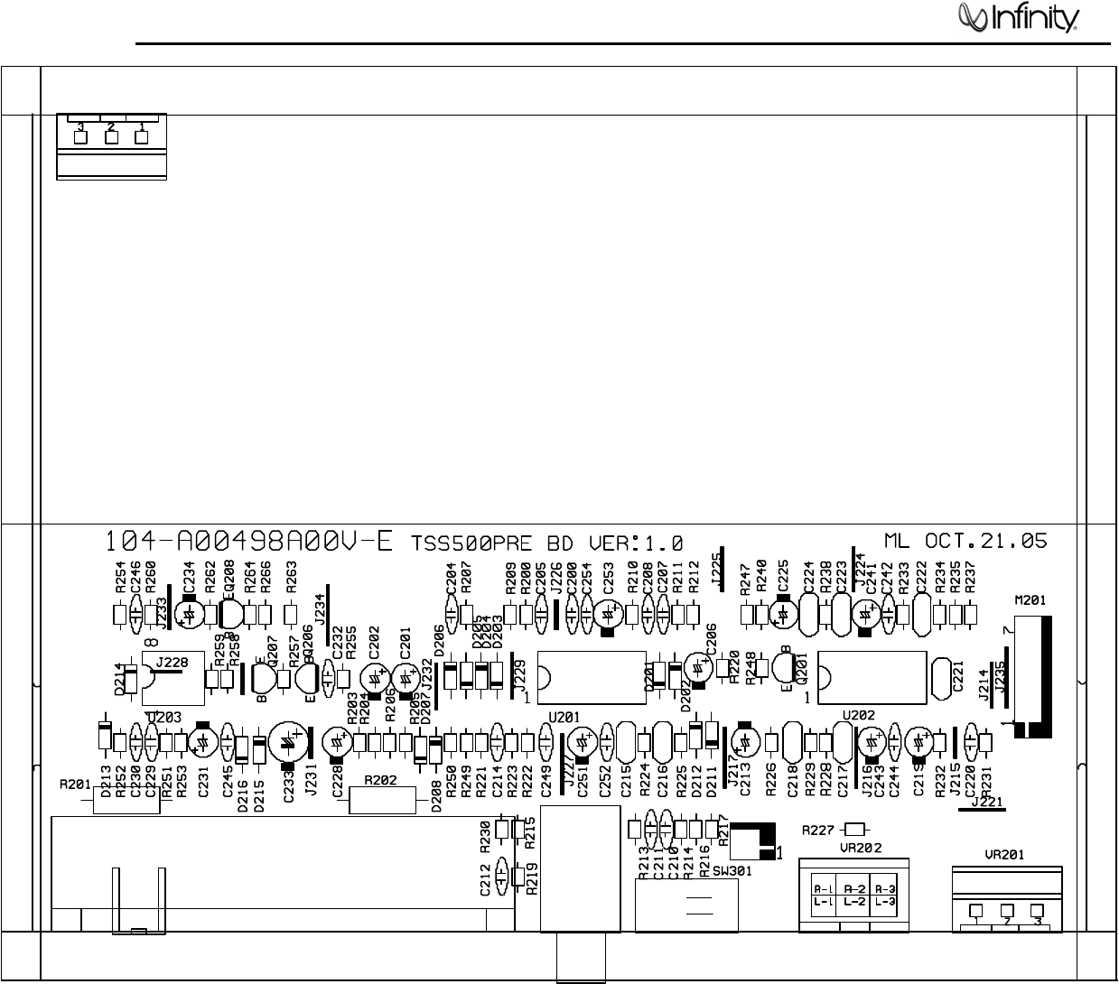
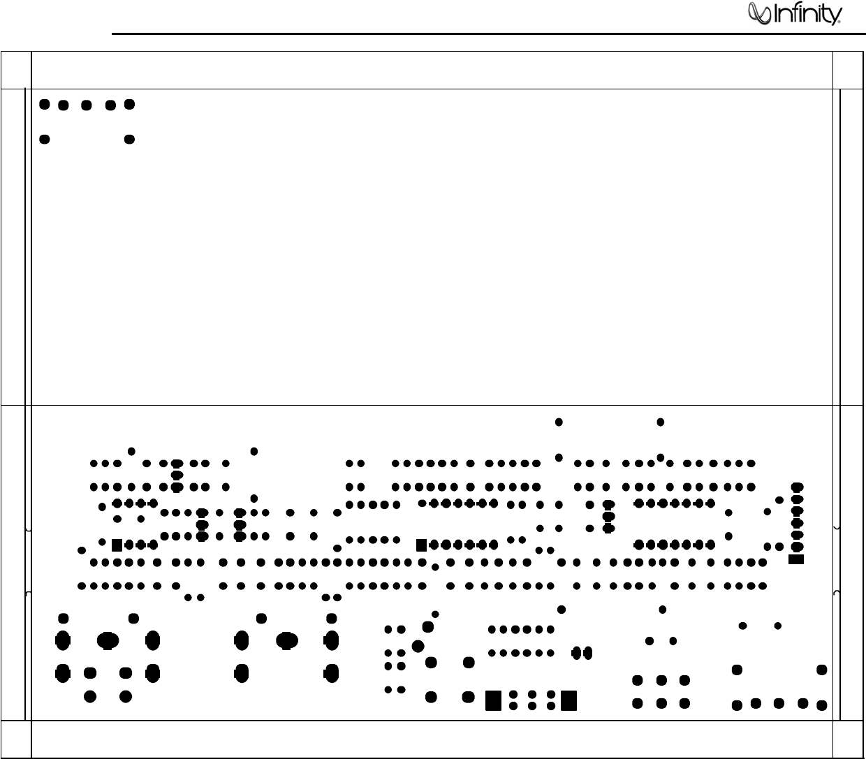
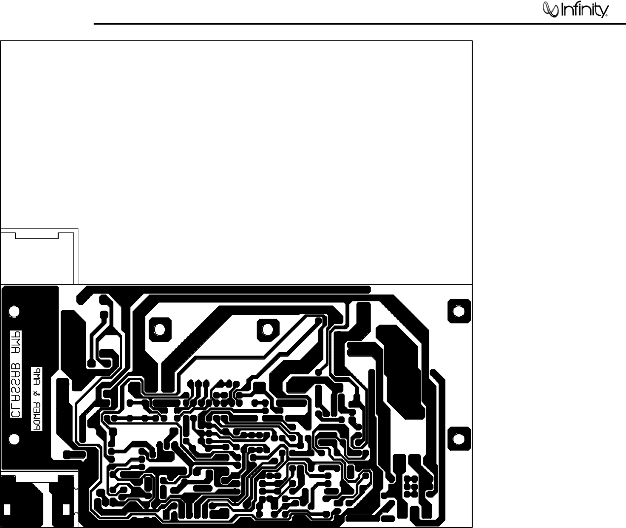
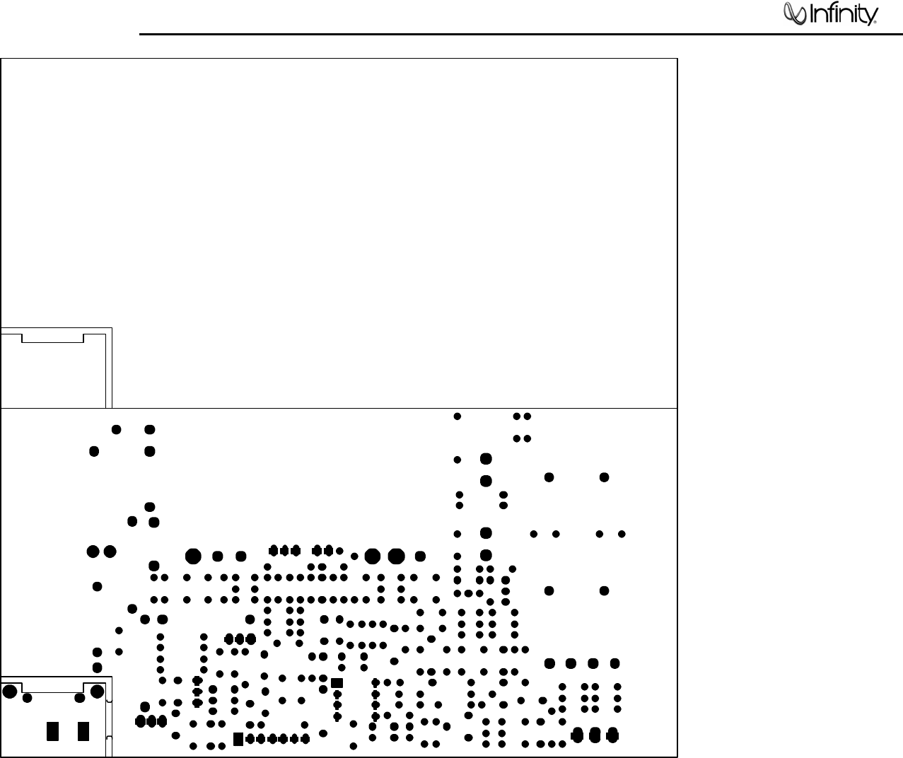
PCB DRAWINGS. .. . . . . . . . . . . . . . .. . . . . ……………………………….. …12
ELECTRICAL PARTS LIST …………. .... . .. . . . . . ……………………... . . . 20
IC – TRANSISTOR PINOUTS . … . . .. . . . . . ………………………….... . . . 24
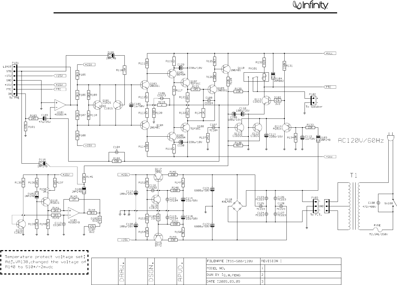
SCHEMATIC DIAGRAMS . . …………………………………….……………. . .25
TSS-Sub500 Specifications
Frequency Range: 39Hz – 150Hz (±3dB)
Amplifier Output: 100 watts RMS
Low-Frequency Driver: 8" (203mm)
Crossover Frequency: 120Hz, 24dB/Octave (line-level [non-LFE] input)
Dimensions (H x W x D): 15-7/8" x 13-5/8" x 14-5/8"
(403mm x 346mm x 371mm)
Weight: 31.7 lb (14.4kg)
Infinity continually strives to update and improve existing products, as well as create new ones. The specifications
and construction details in this and related Infinity publications are therefore subject to change without notice.
1
TSS-Sub500
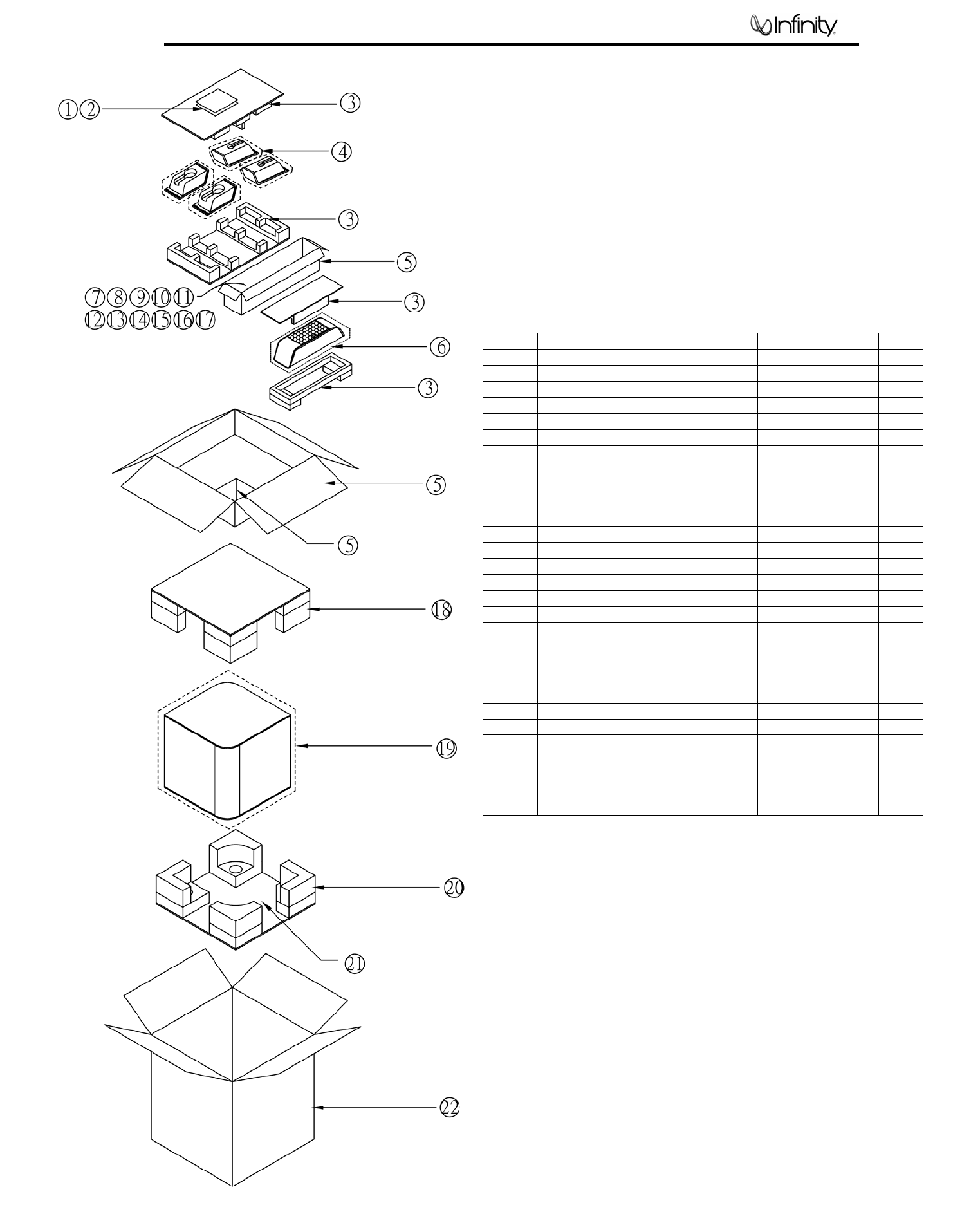
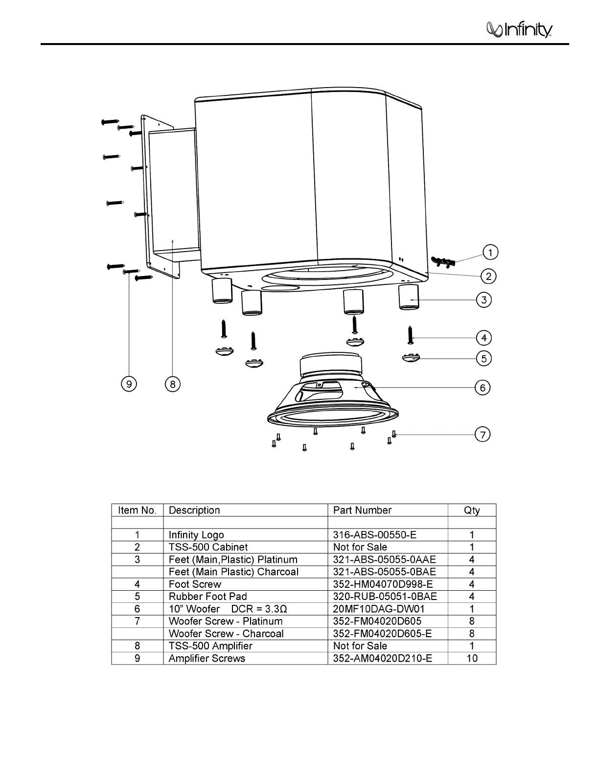
Item # Description Part Number Qty
1 Warranty Card 405-000-05110-E 1
2 Owner’s Manual 406-000-05307-E 1
3 Packing Not for Sale 1
4 Packing Bag Not for Sale 4
5 Inner Carton Not for Sale 1
6 Packing Bag Not for Sale 1
7 Nut wrench (metal bar) 399-FE-00630-E 1
8 15’ RCA cable 370-000-00273-E 1
9 Rubber feet for stands (Platinum) 373-000-05051-E 1
Rubber feet for stands (Charcoal) 373-000-05050-E 1
10 Screw for stands (5) ¼ x 20 x1” (Platinum) 371-000-05108-E 1
Screw for stands (5) ¼ x 20 x1” (Charcoal) 371-000-05114-E 1
11 Wall Bracket ball end (5) (Platinum) 373-000-05054-E 1
Wall Bracket ball end (5) (Charcoal) 373-000-05055-E 1
12 40’ Wire set (2) 370-000-00276G-E 2
13 20’ Wire set (3) 370-000-00277G-E 3
14 Satellite stand (Platinum) 325-ABS-05126-0VAE 4
Satellite stand (Charcoal) 325-ABS-05127-0BAE 4
15 Wall bracket 398-ABS-00317-0VAE 5
16 Center table stand (Platinum) 325-ABS-05127-0VAE 1
Center table stand (Charcoal) 325-ABS-05126-0BAE 1
17 Rubber gasket for stand 336-RUB-05200-0VAE 1
18 Subwoofer Top Packing 431-000-05639-E 1
19 Packing Bag Not for Sale 1
20 Subwoofer Btm Packing 431-000-05640-E 1
21 Desiccant Not for Sale 3
22 Outer Carton (Platinum) 402-000-05533-E 1
Outer Carton (Charcoal) 402-000-05534-E 1
TSS-500 PACKING/ACCESSORIES
2
TSS-Sub500
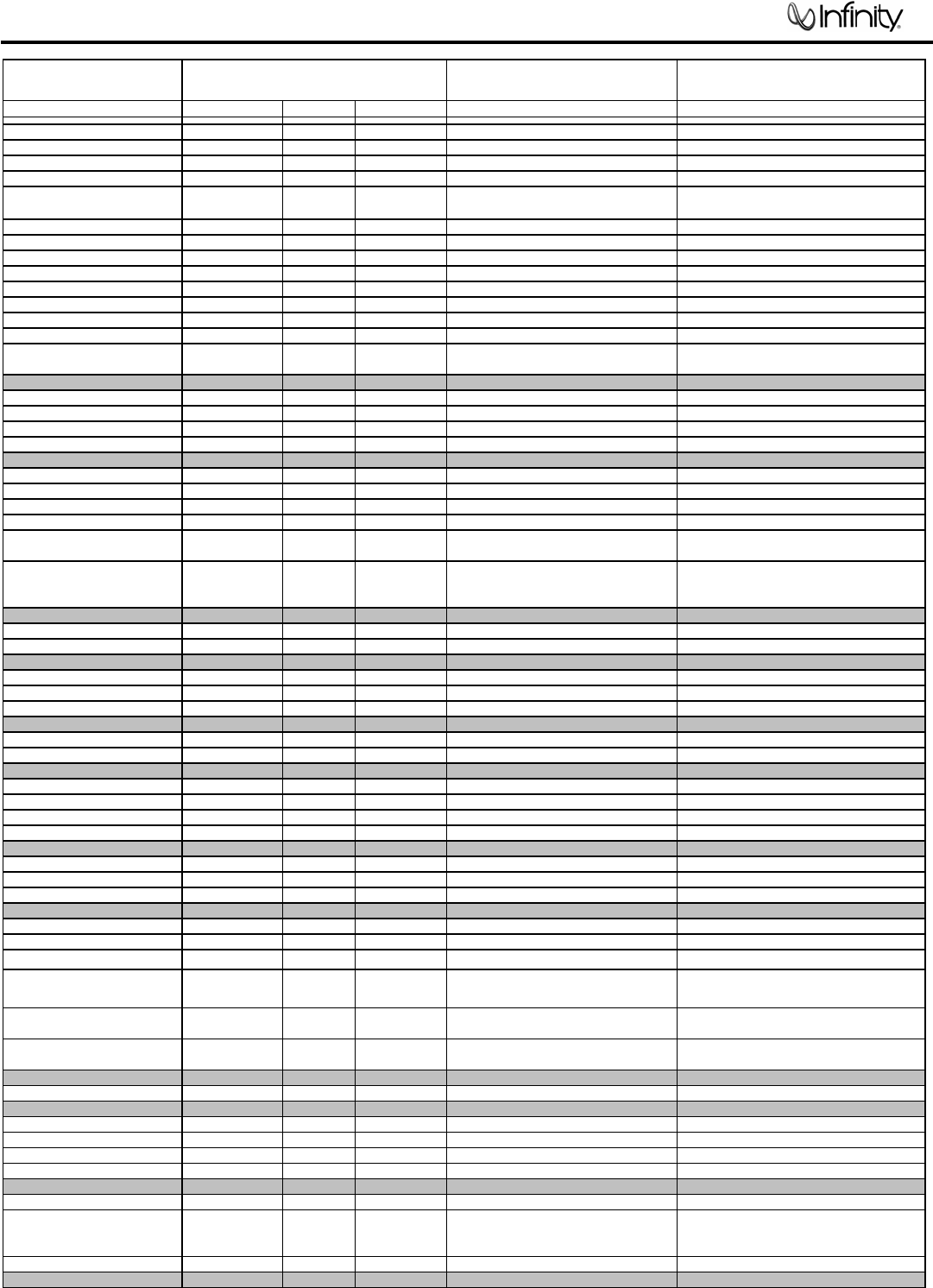
TSS-Sub500 100W Powered Sub/ Plate Amp
LINE VOLTAGE
Y
es/No Hi/Lo Line Unit Notes
US 120VAC/60Hz Yes 108-132 Vrms Normal Operation
Europe 220-240VAC, 50-60Hz Yes 220-240 Vrms Normal Operation
Parameter Specification Unit QA Test Limits Conditions Notes
Amp Section
Type (Class AB, D, other) AB AB n/a 120V Model External Sink required
Type (Class AB, D, other) G G n/a 230V Model External Sink required
Load Impedance (speaker) 4 Ohms n/a Nominal
Rated Output Power 100 Watts 95 Single input driven
THD@ Rated Power 0.5 % 1 22K filter
THD @ 1 Watt 0.1 % 0.5 22K filter
DC Offset 10 mV-DC 50 @ Speaker Output
Damping factor >100 DF 100 50Hz, 4 Ohms load
Measured at amplifier board speaker output
terminals, Output power 90 Watts
Input Sensitivity
Input Frequency 50 Hz 50 Nominal Freq.
Line Input (L&R) 13.8 mVrms ±2dB To 1 Watt Single input driven, AP Zo=600 Ohms
LFE Input 8.62 mVrms ±2dB To 1 Watt LFE input driven only, AP Zo=600 Ohms
Signal to Noise
SNR-A-Weighted 100 dBA 85 rel. to rated power A-Weighting filter
SNR-unweighted 80 dBr 80 rel. to rated power 22K filter
SNR @ 1W-unweighted 60 dBr 60 rel. to 1W Output 22K filter
Residual Noise Floor 1 mVrms 2
Volume @max, using RMS reading
DMM/VOM (or A/P)
Residual Noise Floor 1 mVrms(max) 2
Volume @max, w/ A/P Swept Bandpass
Measurement (Line freq.+ harmonics)
Input Impedance
Line input L&R , LFE >10 K ohms n/a Nominal
Filters
Low Pass (fixed or variable) 4th order fix -- ±2dB
Subsonic filter (HPF) 2nd order Hz ±2dB
Limiter (yes/no) YES -- Functional
THD at Max. Output Power 1 % Functional
Features
LFE Input YES Functional
Volume pot Taper (lin/log) LOG -- Functional
ATO YES Functional
Input Configuration
Line In (L,R) L ,R -- Functional RCA inputs
Line level in LFE LFE Functional
Signal Sensing (ATO)
Auto-Turn-On (yes/no) YES -- Functional
ATO Input Frequency 50 Hz Functional
ATO Level 2 mV Functional
2mV@50Hz into Line Input w/ 1 ch.
driven
ATO Turn-on time 5 ms Functional
Amp connected and AC on, then input
signal applied
Auto Mute/ Turn-OFF Time 10 minutes Functional T before muting, after signal is removed Auto turn of time (T) must be 5 > T <15
Power on Delay time 3 sec. Functional AC Power Applied
Transients/Pops
ATO Transient 5 mV-peak 10 Speaker Outputs
Turn-on Transient 50 mV-peak 100 Speaker Output AC Line cycled from OFF to ON
Turn-off Transient 50 mV-peak 100 Speaker Output AC Line cycled from ON to OFF
Efficienc
y
Stand-by Input Power 12 Watts 15 @ nom. line voltage
Maximum allowable input power under
nominal Input voltage and frequency, HOT
or COLD operation.
Power Cons.@rated power 195 Watts 210 @ nom. line voltage 100 Watts @ 4 Ohms nominal line voltage
3
TSS-Sub500
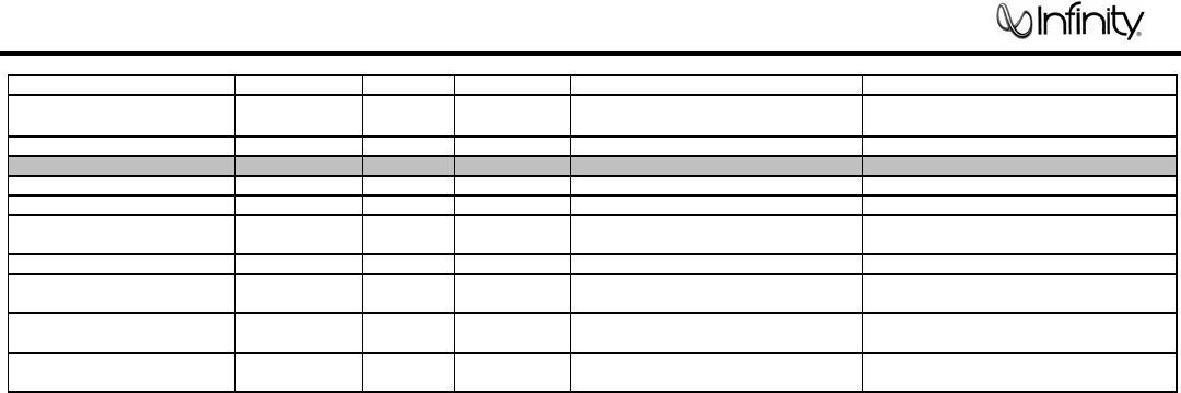
Parameter Specification Unit QA Test Limits Conditions Notes
Protection
Short Circuit Protection YES -- Functional Direct short at output
Thermal Protection 65 deg. C -- Functional @1/8 max unclipped Power
Temperature rise should not exceed 35K
rise
DC Offset Protection YES -- Functional DC present at Speaker Out leads Relay or crowbar (for driver/fire protection)
Line Fuse Rating External fuse with UL/SEMKO rated holder
120 VAC 2.5 Amps
Type-T or Slo Blo, Fuse Markings T2.5A,
250V
230 VAC 1.25 Amps
Type-T, Low breaking capacity, Fuse
markings T1.25AL, 250V
4
TSS-Sub500
5TSS-500
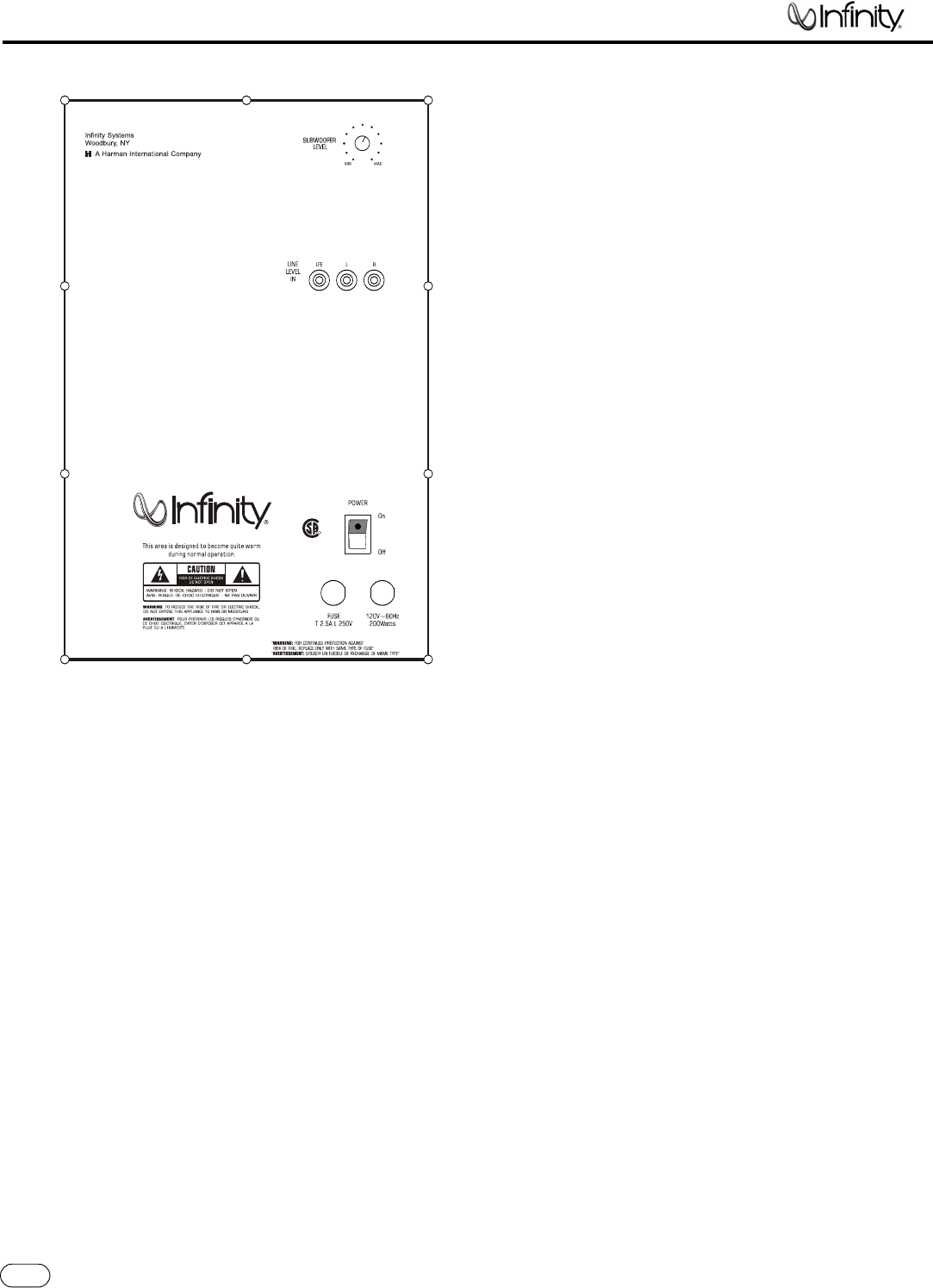
SUBWOOFER CONTROLS
Rear Panel
A Few Suggestions
We recommend that you do not operate your speakers or
subwoofer with the bass, treble and loudness controls set to
full boost.This will place undue strain on your electronics and
speakers and could damage them.
The volume control setting on your processor/preamp or receiver
is not a specific indication of the overall loudness level of the
speakers.The only important consideration is the loudness level at
which the system can be played, regardless of where the volume
control is set.
Always turn down the volume control setting on your processor/
preamp or receiver when changing a cassette or CD,or switching
inputs to AM or FM operation. Excessively loud transients (clicks or
popping sounds) can damage the satellite speakers and possibly
the subwoofer.
Important!
Whenever changing cables, pulling plugs, etc.,ALWAYS TURN OFF
ALL EQUIPMENT, including the subwoofer.
¡Subwoofer Level Control
™LFE Input
£Line-Level Inputs
¢Power Switch
This area is designed to become quite warm
during normal operation.
This area is designed to become quite warm
during normal operation.
This area is designed to become quite warm
during normal operation.
NRTL/C
CSA 22-2 NO.1
UL1492
R
TSS-Sub500
¡
™£
¢
TSS-500 OM 1/20/06 2:45 PM Page 8
5
TSS-Sub500
6
TSS-500
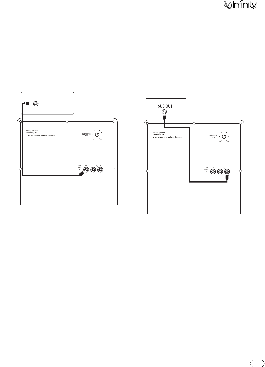
SUBWOOFER CONNECTIONS
If your receiver/processor does not contain
aDolby Digital or DTS processor but has a
subwoofer output:
If you have a Dolby®Digital or DTS®receiver/
processor with a low-frequency-effects (LFE)
or subwoofer output:
SUBWOOFER OR
LFE OUTPUT
TSS-Sub500/230
RECEIVER/PROCESSOR
TSS-Sub500/230
15' (4.6m) subwoofer
cable included
15' (4.6m) subwoofer
cable included
NOTE: If your receiver/processor has only one sub out,
you may use either the L or R input.
TSS-500 OM 1/20/06 2:45 PM Page 9
6
TSS-Sub500

7TSS-500
OPERATION
Surround Modes
When using the TSS-500 in a Dolby Digital or DTS home theater
system, make sure all speakers are set to “Small”. When using the
system in a Dolby Pro Logic®home theater system, make sure the
receiver’s center channel mode is set to “Normal.”
Some Dolby Digital-equipped receivers/processors offer different
setup options for each source or surround mode (e.g., CD-stereo,
videotape, Dolby Digital, Pro Logic). In each case, follow your
equipment’s instructions to ensure that the subwoofer output is
turned on and that the speakers are set to “Small”in each mode.
If your receiver has adjustable crossover settings,we recommend
the subwoofer crossover be set between 100Hz and 120Hz.
Power On
Plug your subwoofer’s AC cord into a wall outlet. Do not use the
outlets on the back of the receiver.
Initially set the Subwoofer Level Control 1to the“MIN”position.
Turn on the subwoofer by pressing the Power Switch 4on the
rear panel.
Turn on your entire audio system and start a CD or movie
soundtrack at a moderate level.
Auto On/Standby
With the Power Switch 4in the ON position, the LED on the back
will remain lit in green or red to indicate the ON/STANDBY mode of
the subwoofer.
RED = STANDBY (No signal detected,Amp Off)
GREEN = ON (Signal detected,Amp On)
The subwoofer will automatically enter the Standby mode after
approximately 10 minutes when no signal is detected from your
system.The subwoofer will then power ON instantly when a signal
is detected. During periods of normal use, the Power Switch 4
can be left on.You may turn off the Power Switch 4for extended
periods of nonoperation, e.g., when you are away on vacation.
Adjust Level
Turn the Subwoofer Level Control 1up about halfway. If no sound
emanates from the subwoofer,check the AC-line cord and input
cables.Are the connectors on the cables making proper contact?
Is the AC plug connected to a “live”receptacle? Has the Power
Switch 4been pressed to the “On”position? Once you have
confirmed that the subwoofer is active, proceed by playing a CD
or DVD. Use a selection that has ample bass information.
Set the overall volume control of the receiver/processor to a
comfortable level.Adjust the Subwoofer Level Control 1until
you obtain a pleasing blend of bass. Bass response should
not overpower the room but rather be adjusted so there is
a harmonious blend across the entire musical range. Many
usershave a tendency to set the subwoofer volume too loud,
adhering to the belief that a subwoofer is there to produce
lots of bass.This is not entirely true.A subwoofer is there to
enhance bass, extending the response of the entire system so
the bass can be felt as well as heard. However, overall balance
must be maintained or the music will not sound natural.An
experienced listener will set the volume of the subwoofer so its
impact on bass response is always there but never obtrusive.
Final Positioning
After correctly connecting the TSS-500 system and verifying
that both the subwoofer and all satellite speakers are playing,
it is time to optimize the system for your particular listening
room. Earlier, you placed the subwoofer in its general location.
Finding the exact location for optimum performance sometimes
only involves moving the speakers up to a few inches in any
direction.We urge you, therefore, to experiment with placement,
if possible, until your speakers deliver their full potential.
MAINTENANCE AND SERVICE
The satellite and subwoofer enclosures may be cleaned using a
soft cloth to remove fingerprints or to wipe off dust.
All wiring connections should be inspected and cleaned or
remade periodically.The frequency of maintenance depends on
the metals involved in the connections, atmospheric conditions
and other factors, but once per year is the minimum.
If a problem occurs, make surethat all connections areproperly
made and clean. If a problem exists in one loudspeaker, reverse
the connection wires to the left and right system. If the problem
remains in the same speaker, then the fault is with the loud-
speaker. If the problem appears in the opposite speaker, the
cause is in another component or cable. In the event that your
TSS-500 ever needs service, contact your local Infinity dealer or
visit www.infinitysystems.com for a service center near you.
TSS-500 OM 1/20/06 2:45 PM Page 10
7
TSS-Sub500
8
TSS-Sub500
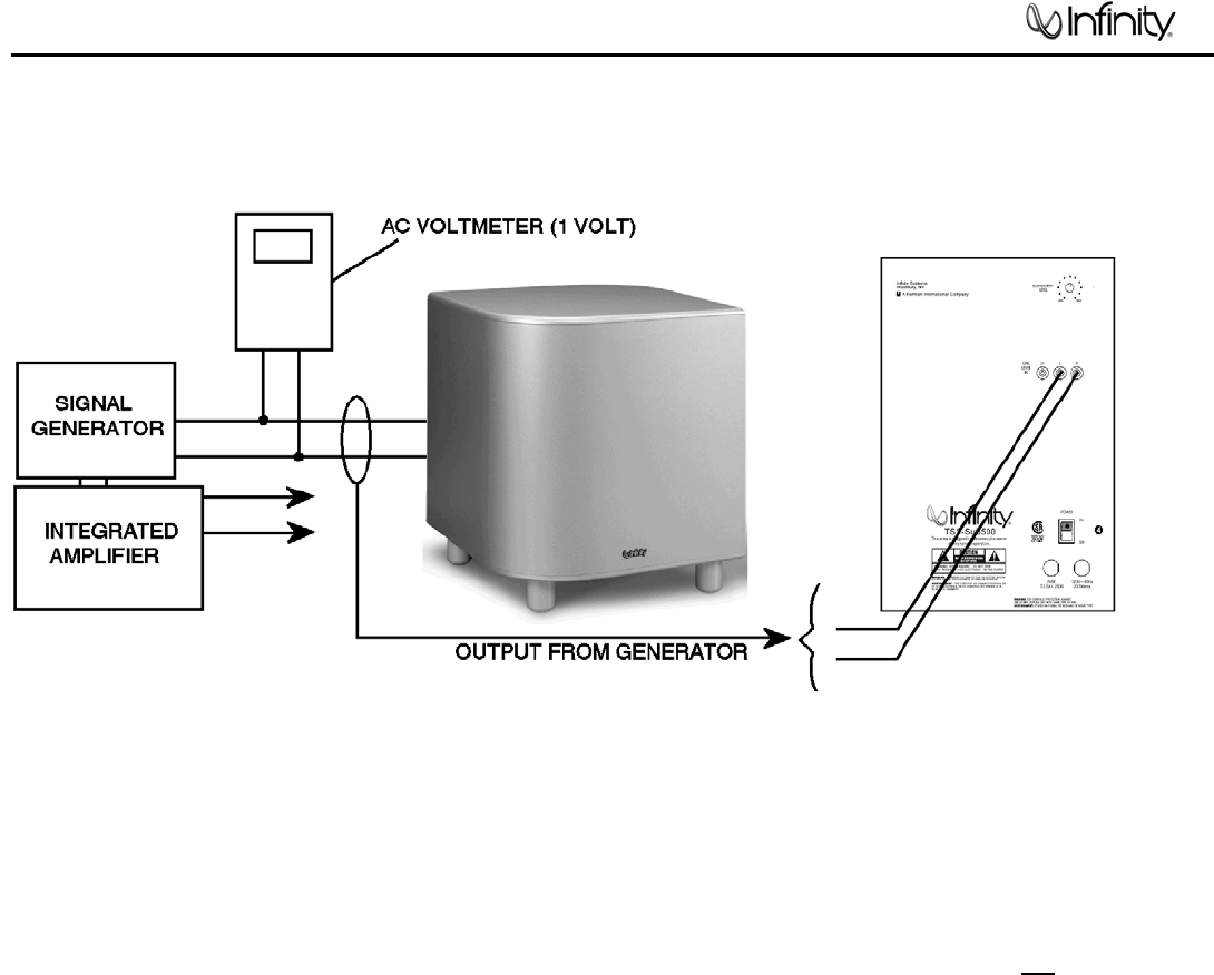
Test Set Up and Procedure
Equipment needed:
• Function/signal generator/sweep generator
• Integrated Amplifier
• Multimeter
• Speaker cables
General Unit Function (UUT = Unit Under Test)
1) From the signal generator, connect one line level (RCA) cable to the Subwoofer Line Level Input jacks L/R
on the UUT. Use a Y-cable from a mono source if necessary to connect to both inputs. Do not connect to
the single LFE input.
2) On the front of the unit, turn the LEVEL control full counterclockwise.
3) Turn on generator, adjust to 100mV, 50 Hz.
4) Plug in UUT; turn the power switch ON. LED should be Red. Turn LEVEL control full clockwise (MAX)
5) LED should now be Green; immediate bass response should be heard and felt from port tube opening.
6) Turn off generator, turn LEVEL control fully counterclockwise, disconnect RCA cable.
Sweep Function
1) Follow steps 3-6 above, using a sweep generator as a signal source.
2) Sweep generator from 20Hz to 300Hz. Listen to the cabinet and drivers for any rattles, clicks, buzzes or
any other noises. If any unusual noises are heard, remove woofers and test.
Driver Function
1) Remove woofer from cabinet; detach + and - wire clips.
2) Check DC resistance of woofer; it should be 3.3 ohms ±10%
3) Connect a pair of speaker cables to driver terminals. Cables should be connected to an integrated amplifier
fed by a signal generator. Turn on generator and adjust so that speaker level output is 5.0V.
4) Sweep generator from 20Hz to 1kHz. Listen to driver for any rubbing, buzzing, or other unusual noises.
9
TSS-Sub500
10
TSS-Sub500
TSS500
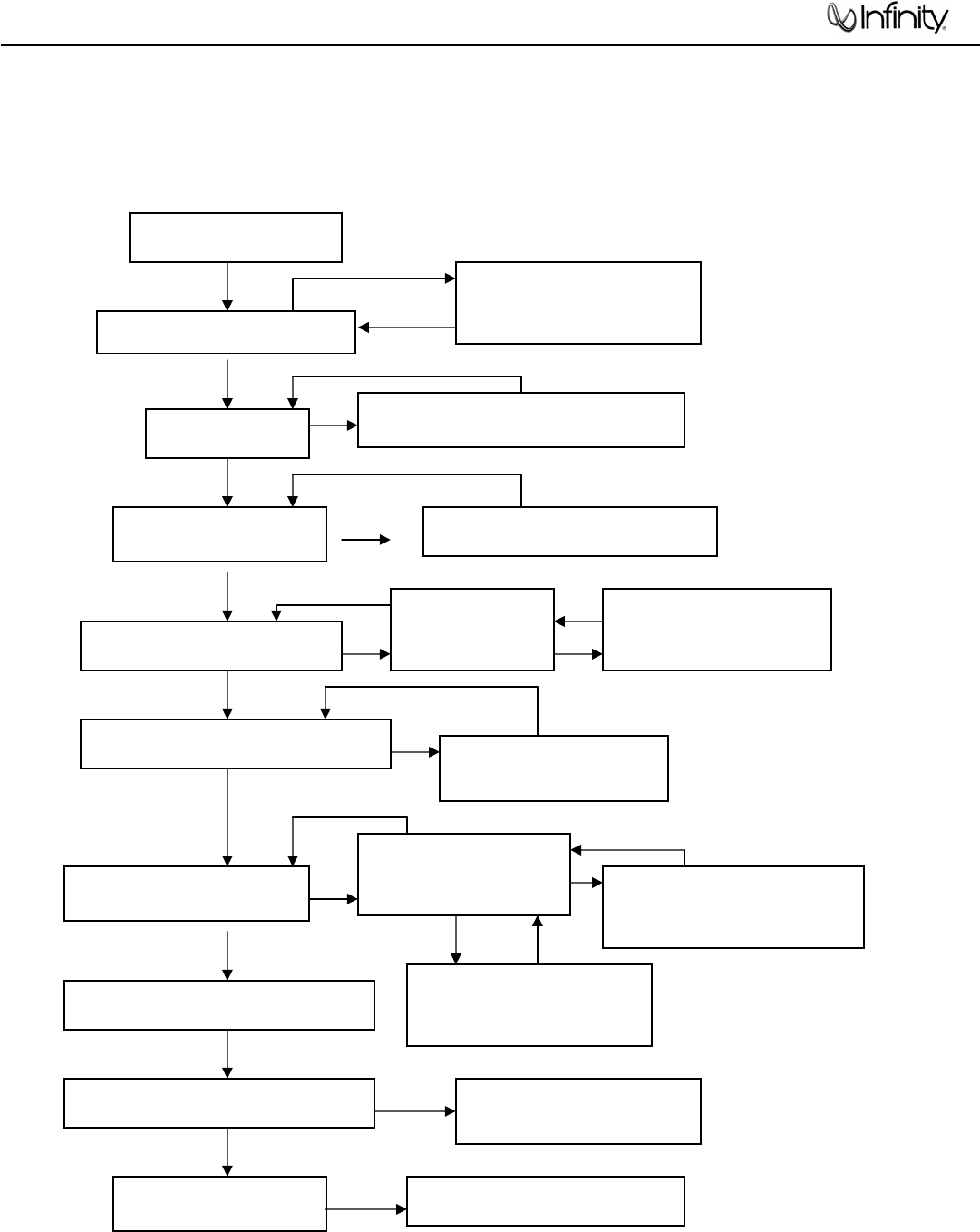
Troubleshooting Flow Chart
no
yes
yes
yes no
yes
yes
LED red
LED light blue yes yes
no
yes yes no
no
yes
yes yes
no
no
yes yes
yes
no
yes
yes
AMP no signal out
DC volta
g
e check ±Vcc
Check +/-15v
Led light blue or red
Check fuse, transformer,
D110,D115 etc
Check RLY101,D102,Q113,114 Check Q107,108,105,
Q106,103,104,U101,etc
Check ,+vsw& -vsw
DC voltage
Check U101,Q115,116,R138
Check Q117,118,119,D109 etc
Check,Q203,207,U203 etc
Check U202 pin14 signal
Check U201
pin14 signal
Test R121,122 signal
Check P102 signal The Amp ass’y ok, END
Check U201,R226,223 ,
U202,R213,214,C206
etc
Check Q120,121,122,123
Q124,125,126,127 etc
Check limiter board C304 Check U301,R343,344 ,
C340,Q301,302, etc
Change the component
11
TSS-Sub500
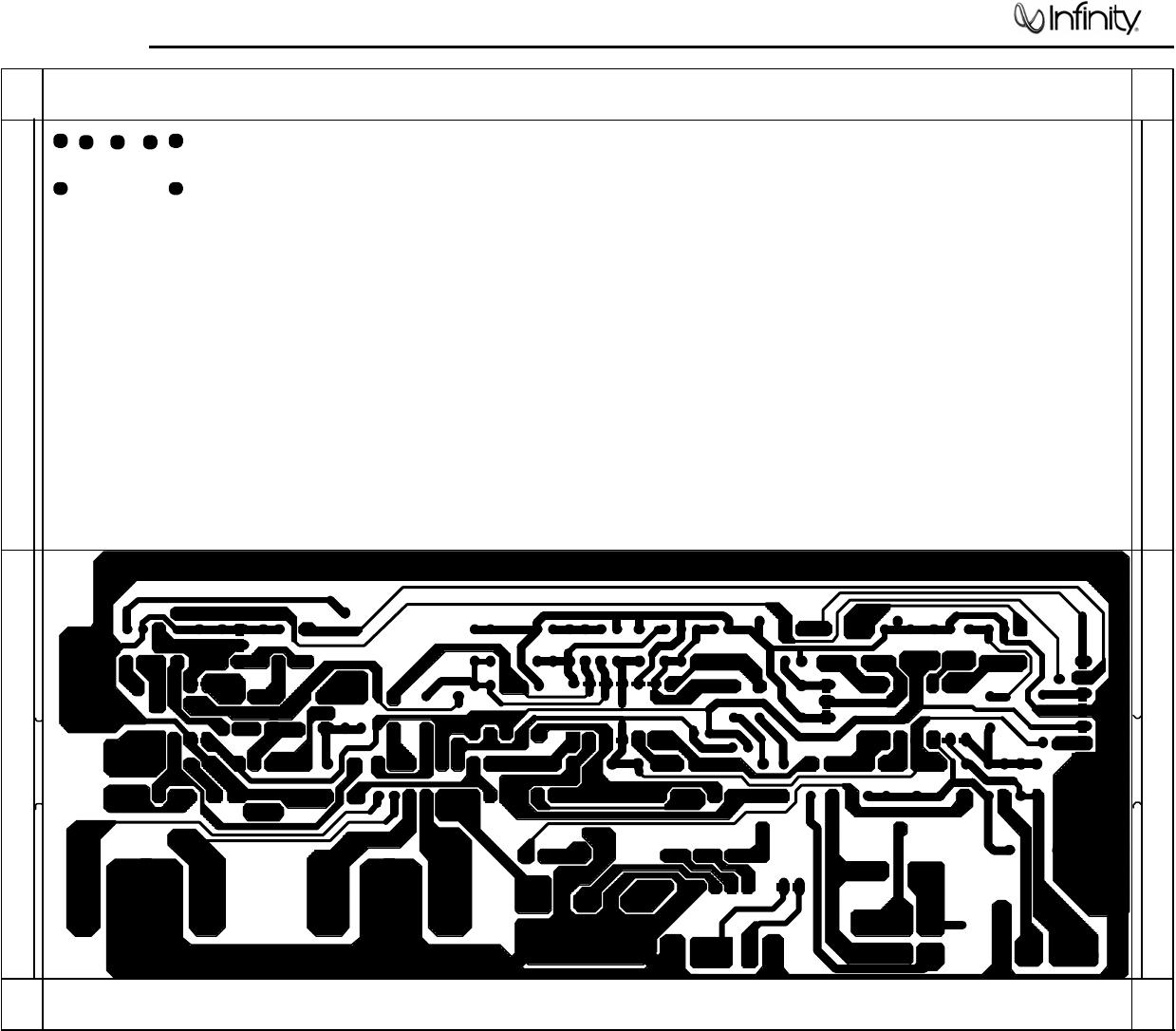
12
TSS-Sub500
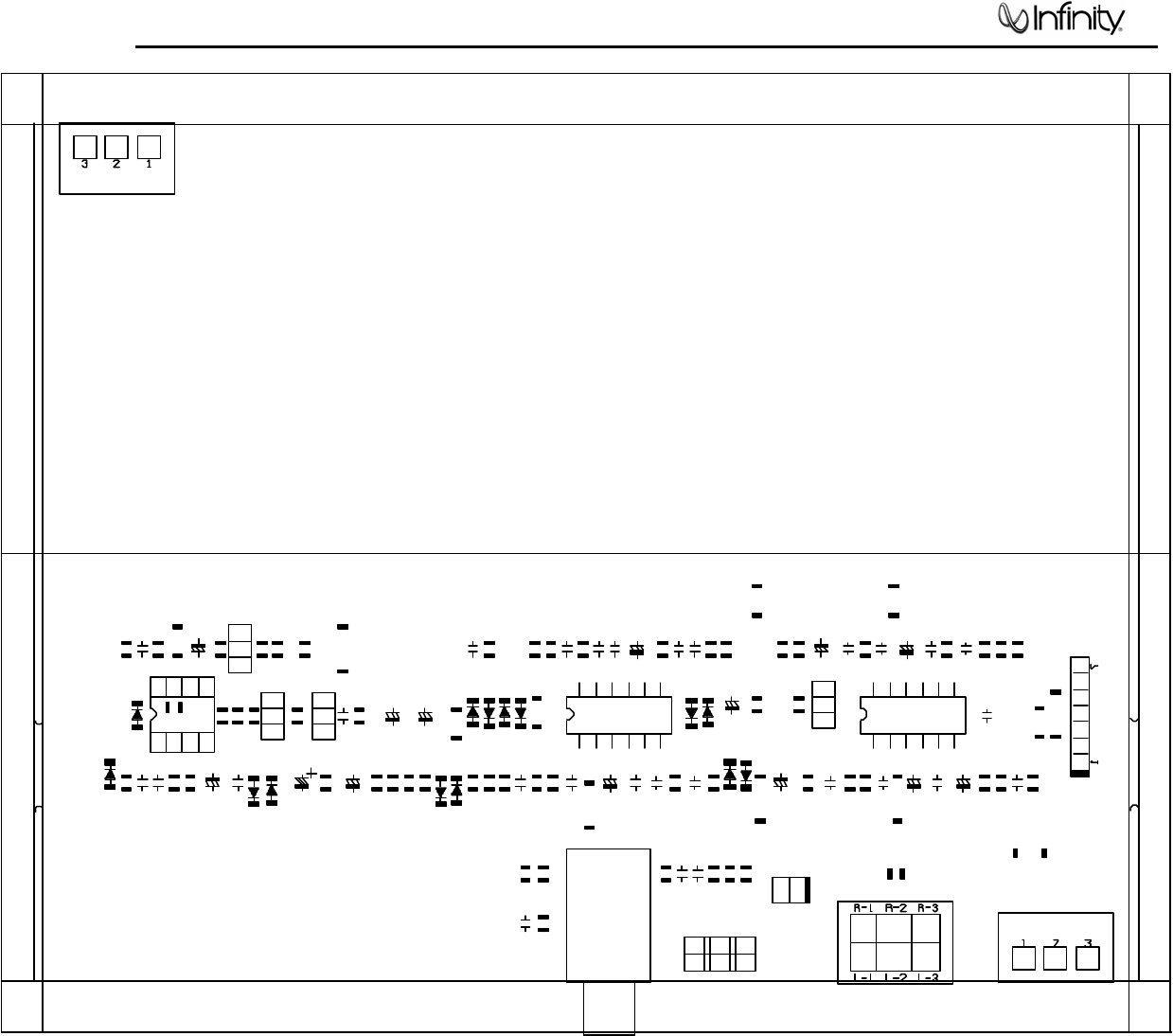
13
TSS-Sub500
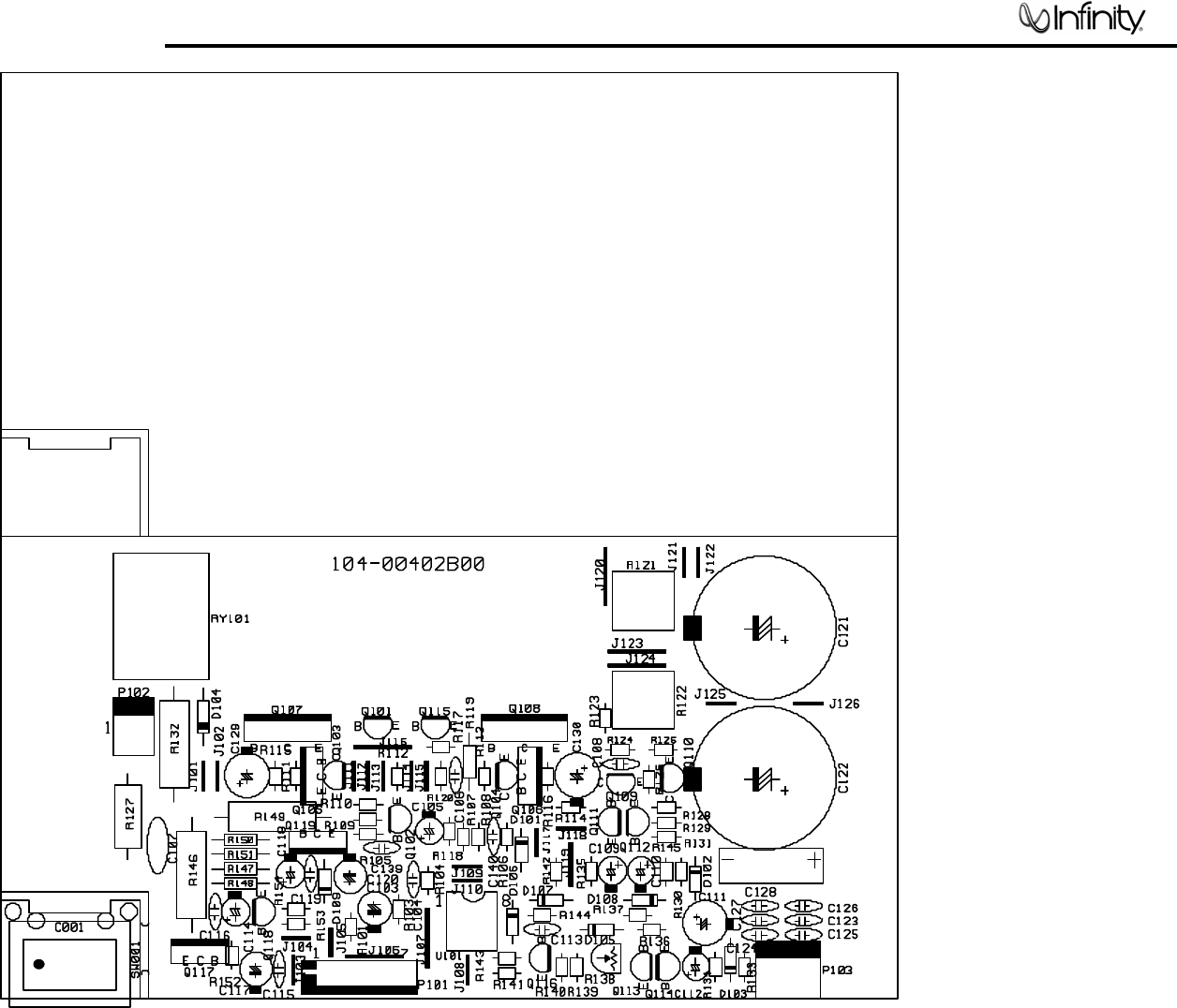
14
TSS-Sub500
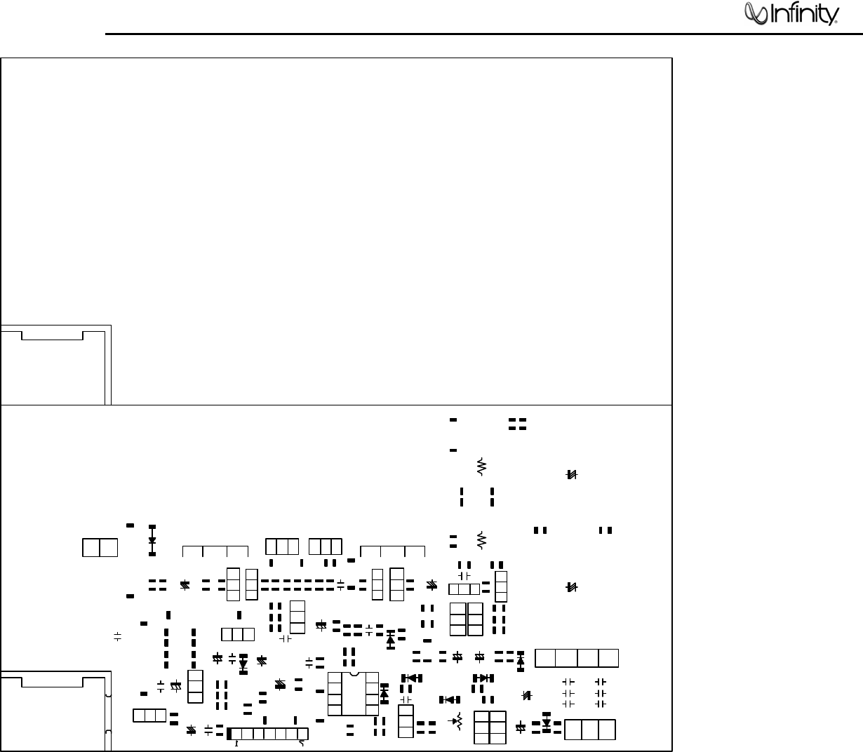
15
TSS-Sub500
16
TSS-Sub500
17
TSS-Sub500
18
TSS-Sub500
19
TSS-Sub500

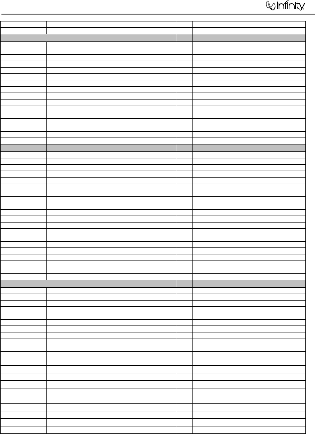
TSS-Sub500 (120v) Electrical Parts List
Part Number Description Qt
y
Reference Designator
PREAMP PCB
Resistors
110-16102j26 Resistor 1K 1/6W ±5% CF 26mm 4 R213,214,215,254
110-16103j26 Resistor 10K 1/6W ±5% CF 26mm 13
R212,216,217,220,221,222,225,228,226,232,
235,240,248
110-16104j26 Resistor 100K 1/6W ±5% CF 26mm 2 R231,266
110-16105j26 Resistor 1M 1/6W ±5% CF 26mm 1 R259
110-16122j26 Resistor 1.2K 1/6W ±5% CF 26mm 1 R264
110-16124j26 Resistor 120K 1/6W ±5% CF 26mm 1 R233
110-16151j26 Resistor 150Ω 1/6W ±5% CF 26mm 1 R253
110-16153j26 Resistor 15K 1/6W ±5% CF 26mm 1 R234
110-16154j26 Resistor 150K 1/6W ±5% CF 26mm 1 R252
110-16183j26 Resistor 18K 1/6W ±5% CF 26mm 2 R262,227
110-16205j26 Resistor 2M 1/6W ±5% CF 26mm 1 R257
110-16223j26 Resistor 22K 1/6W ±5% CF 26mm 4 R238,247,250,255
110-16273j26 Resistor 27K 1/6W ±5% CF 26mm 2 R223,237
110-16333j26 Resistor 33K 1/6W ±5% CF 26mm 1 R249
110-16472j26 Resistor 4.7K 1/6W ±5% CF 26mm 2 R258,260
110-16473j26 Resistor 47K 1/6W ±5% CF 26mm 2 R219,251
110-16512j26 Resistor 5.1K 1/6W ±5% CF 26mm 3 R211,229 ,230
110-16513j26 Resistor 51K 1/6W ±5% CF 26mm 1 R224
115-h503a104 variable Resistor D16 50K/1 A LEVEL 1 VR201
Capacitors
130-2b221k503 disc Capacitor 220P 50V ± 10% 9 C207,208,210,211,212,214,220,230,249
130-3f104z503 disc Capacitor 0.1U 50V +80/-20% 7 C232,242,244,245,246,252,254
130-sl470k503 disc Capacitor 47P 50V ± 10% 1 C229
132-103j503 electrolytic 0.01U 50V ± 5% 2 C223,224
132-104j503 electrolytic 0.1U 50V ± 5% 3 C218,221,222
132-223ja03 electrolytic 0.22uF 100V ± 5% 1 C215
132-473j503 electrolytic 0.047U 50V ± 5% 2 C216,217
135-3105m50 electrolytic 1U 50V ± 20% 1 C228
135-3106m50 electrolytic 10uF 50V ± 20% 8 C206,213,219,231,241,243,251,253
135-3107m16 electrolytic 100uF 16V ± 20% 2 C233,234
135-3226m50 electrolytic 22U 50V ± 20% 1 C225
Semiconductors
192-027c1815gr Transistor 2SC1815GR NPN 3 Q201,206,207
197-031n4148 diode 100mA 75V SIGNAL 1N4148 ROHM 7 D201,202,207,208,211,212,214
199-15000335 zener diode 3.3V 1/2W 52mm 1 D213
190-06m4558d I.C OPA 4558D DUAL OP-AMP 1 U203
190-16t1074cn I .C TL074cm QUAD OP-AMP 2 U201,202
195-10204hgw LED 204HGW 3c 1 D209
Miscellaneous
162-50159201 WIRE ASS'Y 2PIN 150mm 1 for D209
174-0rca326p JACK RCA-326 1 JK202
POWER/MAIN PCB
Resistors
110-14472j26 Resistor 4.7K 1/4W ±5% 26mm 2 R147,150
110-14681j26 Resistor 680Ω 1/4W ±5% 26mm 2 R148,151
20
TSS-Sub500

Part Number Description Qt
y
Reference Designator
POWER/MAIN PCB
110-16101j26 Resistor10 0Ω 1/6W ±5%CF 26mm 1 R120
110-16102j26 Resistor 1K 1/6W ±5% CF 26mm 1 R124
110-16103j26 Resistor 10K 1/6W ±5% CF 26mm 1 R134
110-16105j26 Resistor 1M 1/6W ±5% CF 26mm 1 R143
110-16123j26 Resistor 12K 1/6W ±5% CF 26mm 2 R135,139
110-16152j26 Resistor 1.5K 1/6W ±5% CF 26mm CF 6 R103,123,136,137,141,142
110-16153j26 Resistor 15K 1/6W ±5% CF 26mm 4 R118,145,152,154
110-16154j26 Resistor 150K 1/6W ±5% CF 26mm 1 R131
110-16181j26 Resistor 18Ω 1/6W ±5% CF 26mm 2 R111,114
110-16182j26 Resistor 1.8K 1/6W ±5% CF 26mm 1 R153
110-16223j26 Resistor 22K 1/6W ±5% CF 26mm 3 R128,129,133
110-16332j26 Resistor 3.3K 1/6W ±5% CF 26mm 3 R106,107,144
110-16392j26 Resistor 3.9K 1/6W ±5% CF 26mm 2 R105,108
110-16393j26 Resistor 39K 1/6W ±5% CF 26mm 1 R126
110-16470j26 Resistor 47Ω 1/6W ±5%CF 26mm 4 R112,113,115,116
110-16471j26 Resistor 470Ω 1/6W ±5% CF 26mm 1 R140
110-16472j26 Resistor 4.7K 1/6W ±5% CF 26mm 3 R110,125,130
110-16473j26 Resistor 47K 1/6W ±5% CF 26mm 1 R101
110-16560j26 Resistor 56Ω 1/6W ±5% CF 26mm 1 R117
110-16563j26 Resistor 56K 1/6W ±5% CF 26mm 1 R104
110-16682j26 Resistor 6.8K 1/6W ±5% CF 26mm 1 R109
110-10821jk2 Resistor 820Ω 1W ±5% 10mm 1 R132
110-122r2j15 Resistor 2.2Ω 1/2W ±5% 15mm 1 R127
110-20331jk2 Resistor 330Ω 2W ±5% 5mm 2 R146,149
113-50r10j10 cement Resistor 0.1Ω 5W ±5% 2 R121,122
114-03302m0 semi-fixed Resistor 3K 0.3W 1±20% 1 R138
Capacitors
130-2b102k503 disc Capacitor 1000p 50V±10% 1 C116
130-2f104z503 disc Capacitor0.1u 50V+80/ -20% 4 C108.113.115.119
130-3f473m503 disc Capacitor0.047u 50V±20% 1 C106
130-s1101k503 disc Capacitor100p 50V SL±10% 2 C139,140
132-104j503 mylar Capacitor 0.1u50V ±5% 1 C107
132-223ja03 mylar Capacitor 0.022uF 100V ±5% 4 C124,125,126,128
135-3105m50 mylar Capacitor 1U 50V ±20% 2 C105,112
135-3107m16 mylar Capacitor100uF 16V ±20% 3 C109,117,120
135-3226m50 mylar Capacitor22U 50V ±20% 2 C114,118
135-3227m10 mylar Capacitor220U 10V ±20% 2 C129,130
135-3227m16 mylar Capacitor220U 16V ±20% 1 C111
135-3476m25 mylar Capacitor47U 25V ±20% 1 C103
132-223ja03 mylar Capacitor 0.022uF 100V ±5% 2 C123,127
135-3107m16 electrolytic 100uF 16V ±20% 1 C110
135-4688m50 electrolytic 6800U/50V ±20% D25X45mm 2 C121,122
Semiconductors
192-027c1815gr Transistor 2SA1815GR NPN 5 Q102,111,112,113,118
192-028a1015gr Transistor 2SA1015GR PNP 2 Q114,116
192-1572n5551 Transistor 2N5551 NPN 2 Q103,109
192-1582n5401 Transistor 2N5401 AI-PNP 350V 500MA TO-92 2 Q104,110
197-031n4148 diode 100mA 75V SIGNAL 1N4148 ROHM 4 D101,103,105,108
199-15000335 zener diode3.3V 1/2W 52mm 1 D102
199-15000625 zener diode 6.2V 1/2W 52mm 2 D106,107
199-15001605 zener diode 16V 1/2W 52mm 1 D109
190-06m4558d IC OPA 4558D DUAL OP-AMP 1 U101
192-021tip35c Transistor TIP35C NPN 1 Q107
192-022tip36c Transistor TIP36C PNP 1 Q108
192-027c1815gr Transistor 2SC1815GR NPN 2 Q101,115
192-201d882Y TransistorKSD882Y PNP 1 Q117
21
TSS-Sub500
Part Number Description Qt
y
Reference Designator
POWER/MAIN PCB
192-202b772y TransistorKSD772Y PNP 1 Q119
192-991d669a TransistorHI-SINCERITY HSD669A NPN 1 Q106
192-992b649t Transistor HSB649T PNP 1 Q105
197-00kb1405 diode 4A500V KBL405 BRIDGE 1 D110
197-101n4002 diode IN4002 1 D104
Miscellaneous
162-10202001 wire 26AWC 1007 200mm RED 1
171-udhss124d relay 5A 24V UDH-SS124D 1 RY101
175-1c07v01 wire connector 7PIN PITCH=2.5mm 1 P101
175-1d02v01 wire connector 2PIN PITCH=3.96mm 1 P102
175-1d03v01 wire connector 3PIN PITCH=3.96mm 1 P103
193-3m2520 insulator TO-3P 25x20mm 2 for Q107,108
LIMITER PCB
110-16103j26 Resistor 10K 1/6W ±5% CF 26mm 8 R301,303,304,308,309,314,340,344
110-16183j26 Resistor 18K 1/6W ±5% CF 26mm 1 R302
110-16223j26 Resistor 22K 1/6W ±5% CF 26mm 2 R310,312
110-16273j26 Resistor 27K 1/6W ±5% CF 26mm 1 R341
110-16333j26 Resistor 33K 1/6W ±5% CF 26mm 1 R305
110-16472j26 Resistor 4.7K 1/6W ±5% CF 26mm 2 R342,343
110-16474j26 Resistor 470K 1/6W ±5% CF 26mm 1 R307
110-16751j26 Resistor 750Ω 1/6W ±5% CF 26mm 2 R311,313
110-16755j26 Resistor 7.5k 1/6W ±5% CF 26mm 1 R306
130-2f104z503 disc Capacitor 0.1u 50V +80/-20% 2 C305,306
132-103j503 mylar Capacitor 0.01U 50V ± 5% 2 C302,303
135-3226m50 electrolytic 22U 50V ± 20% 2 C301,340
135-3476m25 electrolytic 47U 25V ± 20% 1 C304
192-027c1815gr Transistor 2SC1815gr NPN 2 Q301,302
197-031n4148 diode 100mA 75V SIGNAL 1N4148 2 D301,302
162-50289001 CABLE ASS'Y wire's 280mm AWG26 WHT 1
175-9f40hr2 coupling 40PIN PITCH=2.54mm HR2*40 0.15 P301
190-16tl074cn I .C TL074cm st QUAD OP-AMP 1 U301
MISCELLANEOUS/MECHANICA
L
123-14j70d Ferrite Core U-16.3*8.2*13(J70)+CASE 1
130-3f472md00 disc Capacitor 4700P 400V ± 20% 1 C001
150-e8604107 Power Transformer EI-86 60HZ 120V TT086996580 1 T1
152-u602015 LineCord SVT FT-2 6FT 1
154-u25006t0 Fuse 2.5A 250V 20mm 1
155-520020 Fuse Holder R3-11 1
162-10082007 WIRE RED 18AWG 80mm 8mm#1015 1
162-50652003 WIRE 650mm RED=205# 0.5T BLK=110# 0.5T 1
176-wjcel wire connector Pin CE-1 1
180-prf1003S switch ROCK RF-1003-BB2-OHA POWER 1 SW100
176-wjce1 wire connector pin CE-1 1
350-EM04012D024 4¢*12 wood screw black 4
351-HM04016A218 M4*16 machine screw black 4
351-AM03008A079 M3*8 machine screw black 6
352-AM03010D065 ¢3*10 P type tapping screw black 2
352-AM03008D040 ¢3*8 B type tapping screw black 8
354-GM04002 M4 nut black 4
362-FE-00013 PCB support L TYPE t=1.6mmS.P.C.C 89*9*1.6T 2
311-ABS-00028 plastic knob 46077-W soft matetial P.V.C. LEVEL 1
335-NYL-00002 wire clip 4K-4 NO-BB 2
22
TSS-Sub500
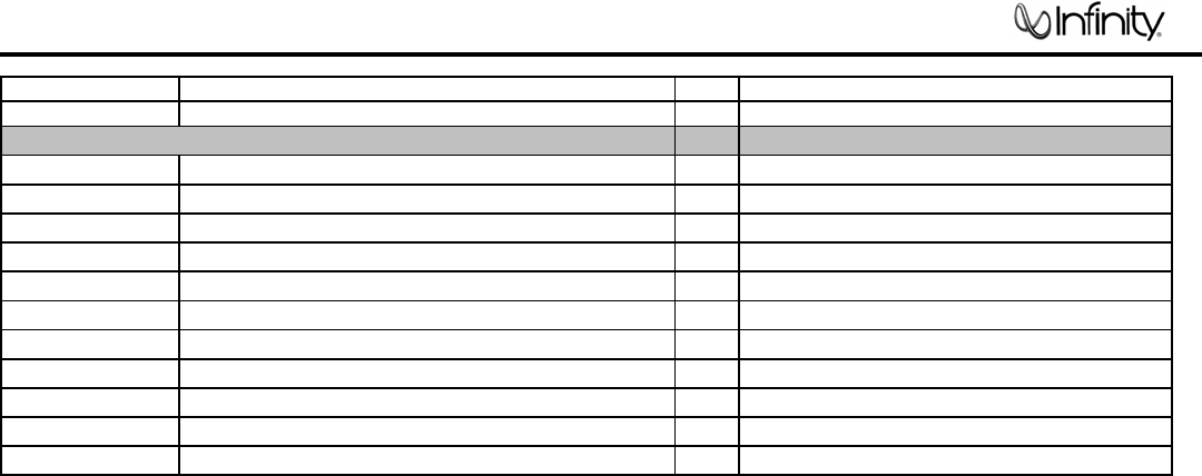
Part Number Description Qt
y
Reference Designator
MISCELLANEOUS/MECHANICA
L
333-EVA-00783 EVA W 198*12*2.0T 2
333-EVA-00807 EVA L 274*12*2.0T 2
333-EVA-00826 EVA W 198*12*1.0T 2
333-EVA-00835 EVA L 274*12*1.0T 2
320-RUB-00033 rubber foot pad 25*21*4t 4
337-CU-00101 copper foil 65L*50W 1
306-ABS-00177 rear Plastic housing 198*298*102mm 1
162-50552003 WIRE UL1007 #16 550mm#110/#205 0.5T 1
302-AL-05048-0BAE rear board 300*200*2.5T black(RoHS) 1
323-AL-00106-0BB HEAT SINK 117.5*71.5*25 anode is black 1
23
TSS-Sub500
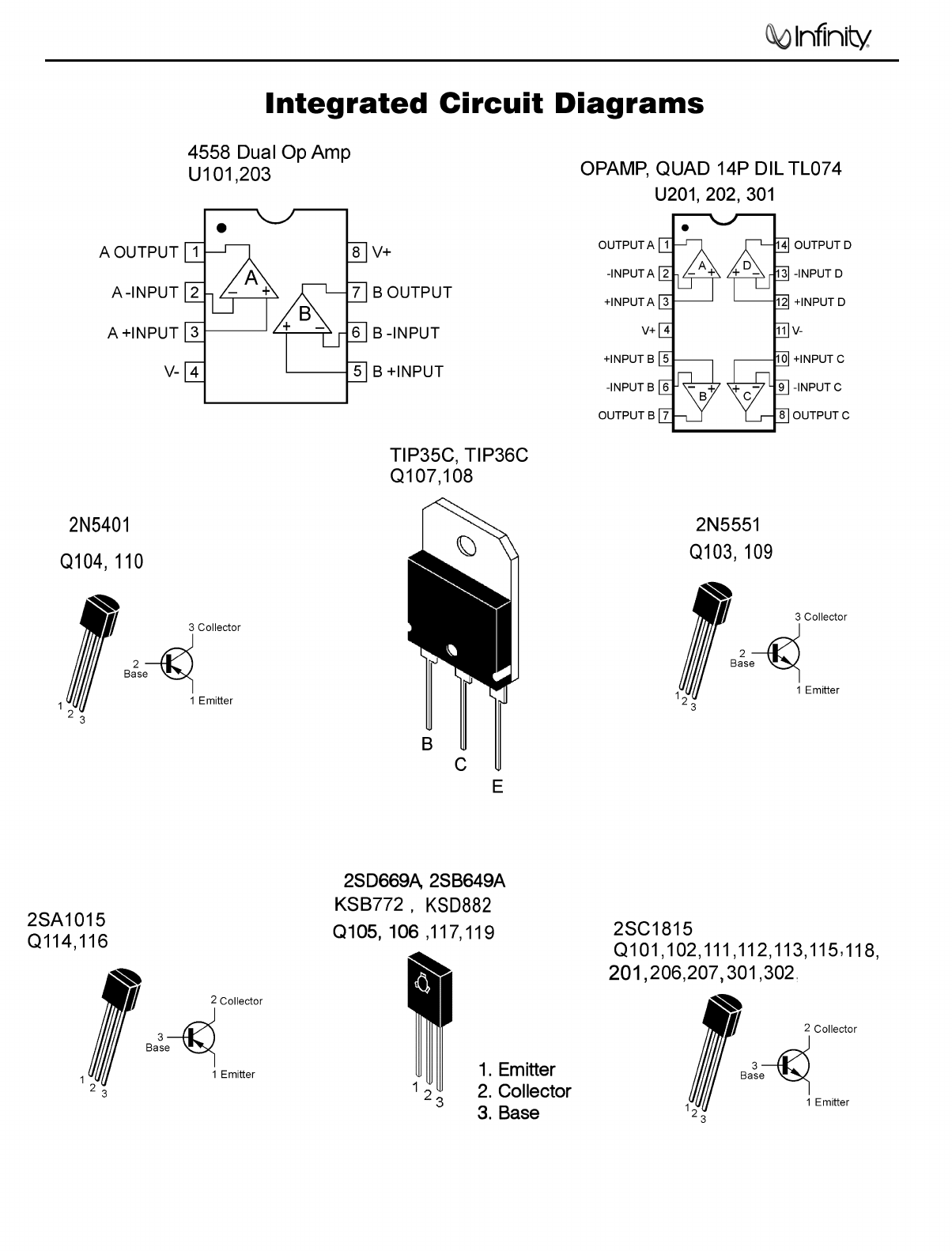
24
TSS-Sub500
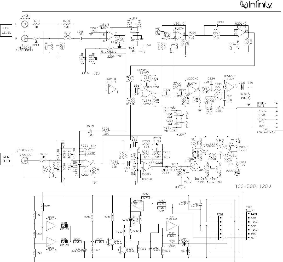
25
TSS-Sub500
26
TSS-Sub500
