Information Station Specialists TR-6000TIS-WB Travelers Information Service Transmitter User Manual
Radio Systems Inc Travelers Information Service Transmitter Users Manual
Contents
- 1. 8
- 2. Users Manual
Users Manual

Radio Systems, Inc. TR-6000 Manual
4/01 Page 1
TR-6000 10 Watt
AM Broadcast Transmitter
Manual

Radio Systems, Inc. TR-6000 Manual
4/01 Page 2
Table Of Contents
Operating Instructions..........................................................................................................3
Overview.....................................................................................................................................3
Available Options........................................................................................................................3
Front Panel Controls....................................................................................................................3
Connections.................................................................................................................................3
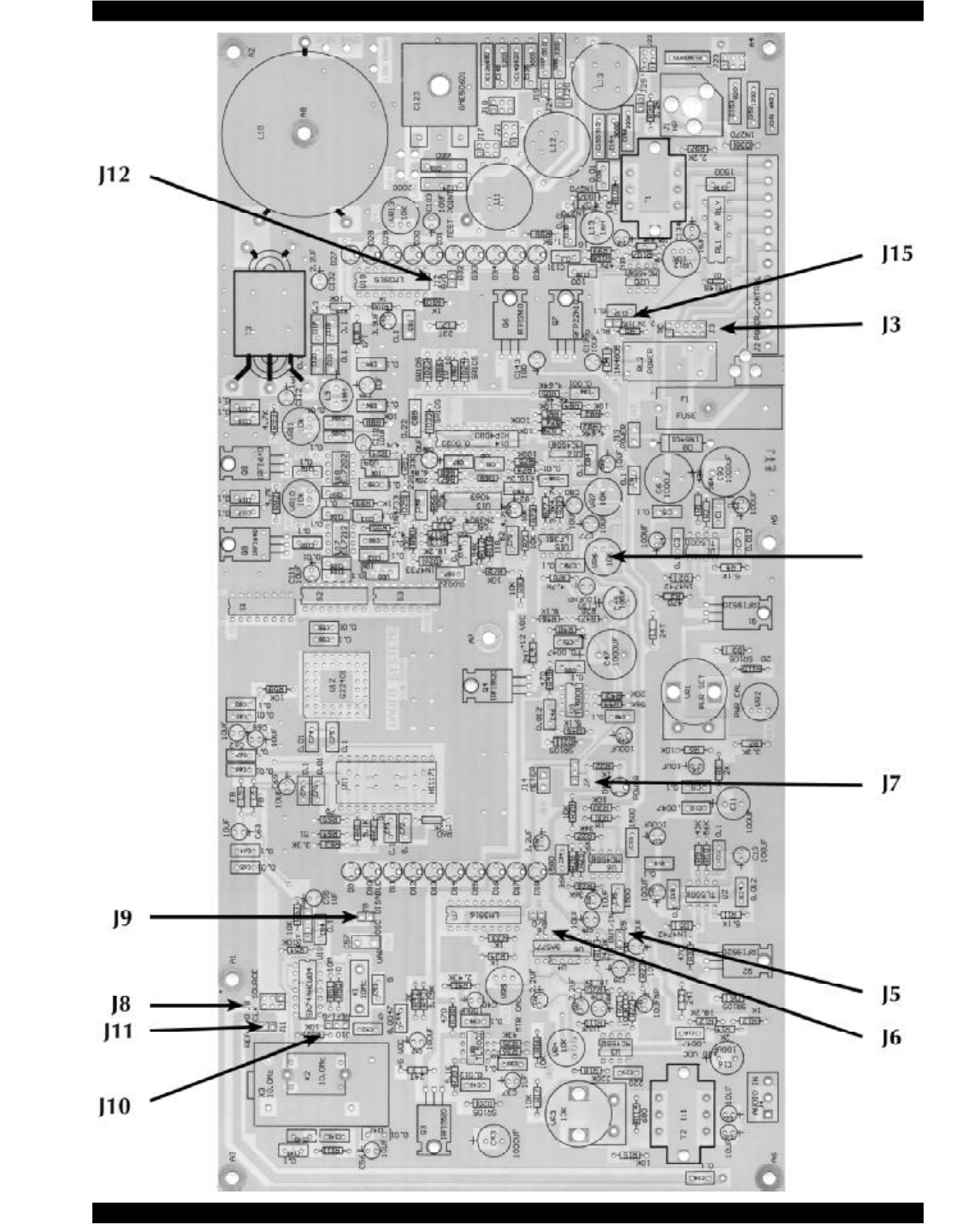
TR-6000 Jumper Settings......................................................................................................4
TR-6000 Frequency Change Procedure.................................................................................6
TR-6000 Test Procedure.......................................................................................................7
Test Point and Calibration Location Illustrations................................................................10
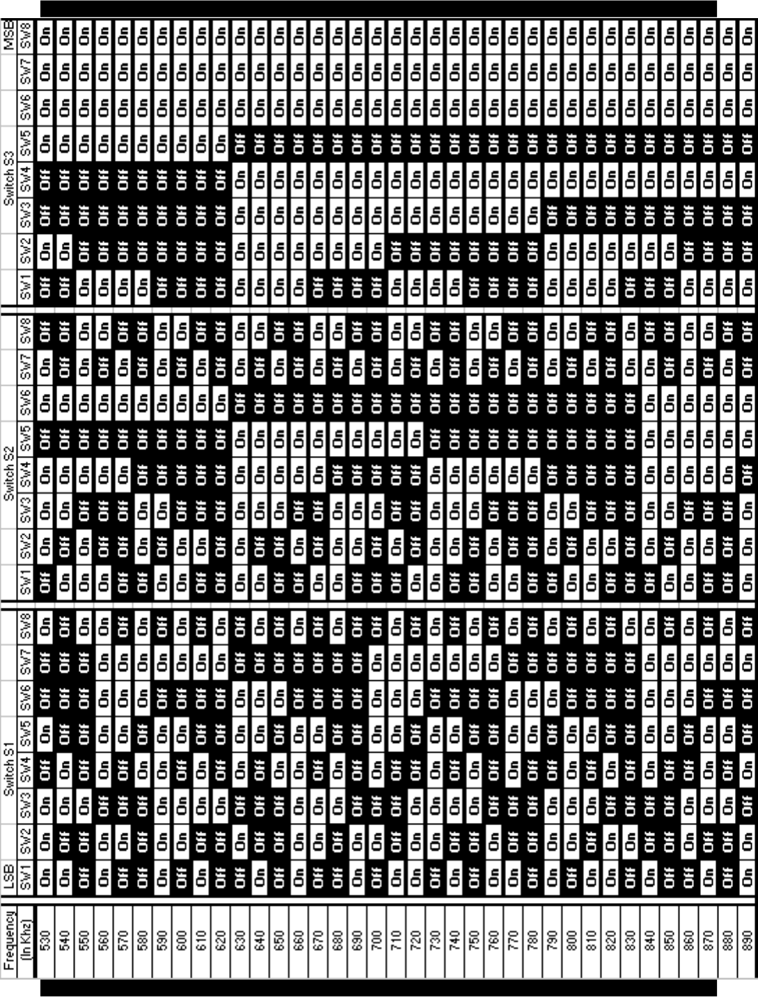
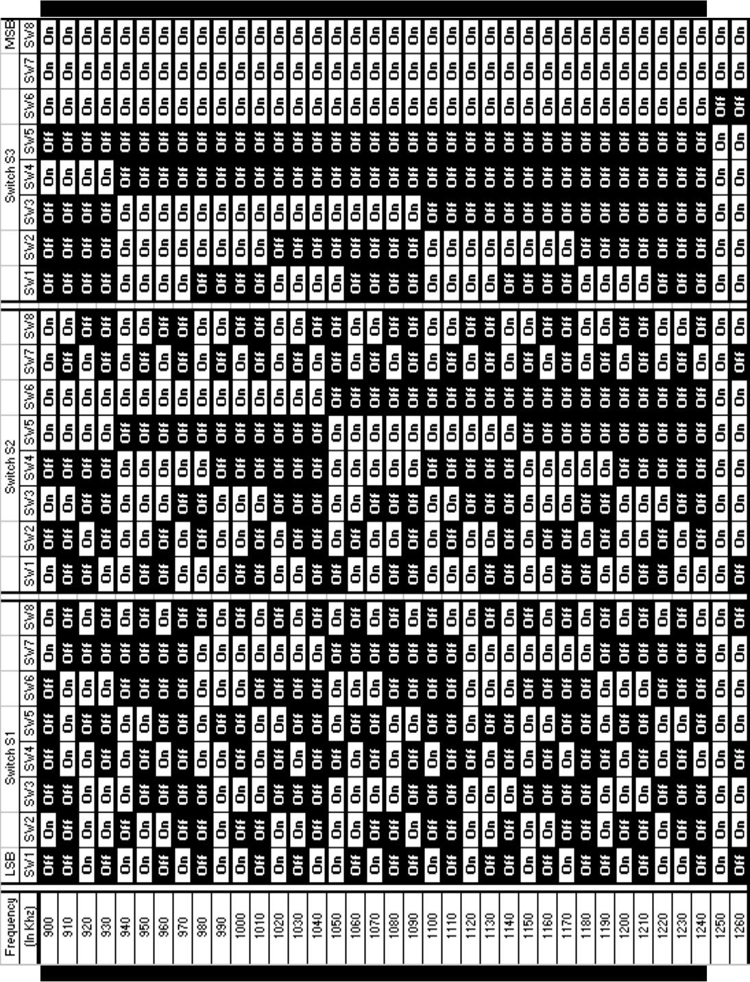
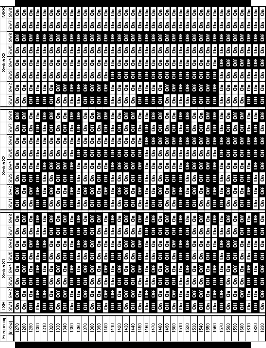
Frequency Programming Chart...........................................................................................12
Bill of Materials..................................................................................................................16
Schematic...........................................................................................................................17
Warranty.............................................................................................................................18
Repair Policy.......................................................................................................................32
Return Instructions.............................................................................................................32

Radio Systems, Inc. TR-6000 Manual
4/01 Page 3
TR-6000 AM Broadcast Transmitter
Operating Instructions
Overview
The TR-6000 is a solid-state, class D AM transmitter specially designed for traveler’s information, carrier
current, roadside radio, and other low-power broadcast band AM applications.
The unit features a frequency synthesized oscillator, full remote control, LED power and audio meters, 0 to
10 watt output power, short circuit protections, balanced audio inputs, and monitor and headphone outputs.
The TR-6000 is shipped factory set for 10-watt operation. 10-watt units are provided with a 24-volt external
power supply. The TR-6000 can be powered by storage batteries (not supplied).
The TR-6000 is FCC certified for TIS operation anywhere within the AM broadcast band.
Available Options
• brackets for wall or 19’ EIA rack mounting
• super stable crystal option @ 1.5 ppm
• ultra stable crystal option
Front Panel Controls
Power switch - supplies DC to the unit
Do not power up without a 50 ohm output load.
Meter switch - illuminates power and VU LED meters.
Leave off to increase efficiency for battery or solar operation.
Power Adjust - sets RF output level
Set (with no modulation required) to desired carrier level on 10 watt scale
Mod(ulation) adjust - set for 100% modulation on VU meter
For TIS operation the internal audio filter must be engaged. Consult the internal parts layout diagram for
location.
Connections
CAUTION: Make all connectors prior to applying DC voltage via the supplied transformer or any
external DC source.
RF out - Connect to 50 ohm load
Audio input - Apply line-level balanced audio source
DC in - Apply 24 volts to 24 volt terminals via DC transformer connect or DC input
screw terminals (do not apply both inputs simultaneously, however DC may be derived from the
DC terminals for low-current applications when the transformer is utilized).
Relay contacts - (Depending on internal strap programming) This relay can control or be controlled by the
transmitter for external device remote control.
Switched monitor audio control - controls the audio output feed to a remote location for remote
monitoring.
Switched monitor audio out - balanced/switched (see above) monitor feed.
Monitor audio out - balanced/non-switched audio feed.
Radio Systems, Inc. TR-6000 Manual
4/01 Page 4
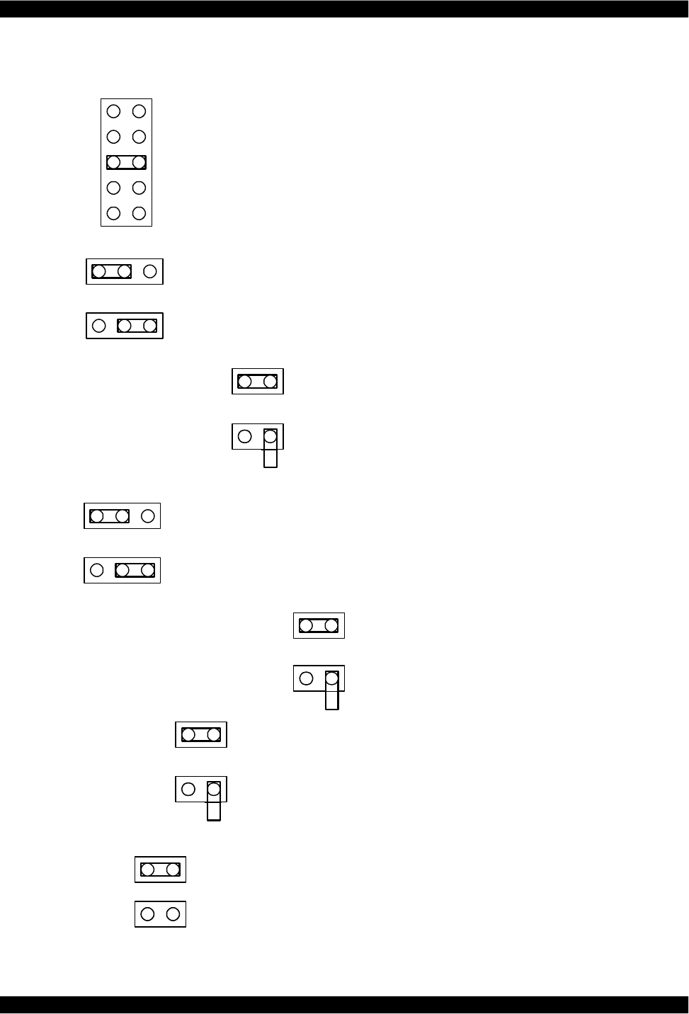
TR-6000 Jumper Settings
J3 Power Control Relay Configuration
- Relay power supplied by main + input (fused)
- Relay power supplied by N.O. contact
- Relay power supplied by common contact
- Relay power supplied by N.C. contact
- Relay power supplied by main + input (unfused)
J5 TIS audio filter enable
TIS filter disabled
TIS filter enabled
J6 VU meter display mode
Install jumper for bar mode bar mode
Leave open for dot mode dot mode
J7 Power LED to follow metering switch
Power LED independent of metering
Power LED follows metering
J9 Standard oscillator disable
Jump to disable the standard oscillator
Enable the standard oscillator
J12 Power meter display mode
Jump for bar mode
Open for dot mode
J15 Relay Supply Voltage
24V Supply Note: Jumper representations on this page are orientated to
match circuit board silk screens.
48V Supply
*
*
*
*
*
*
*
Note: * Indicates Factory Setting
Radio Systems, Inc. TR-6000 Manual
4/01 Page 5
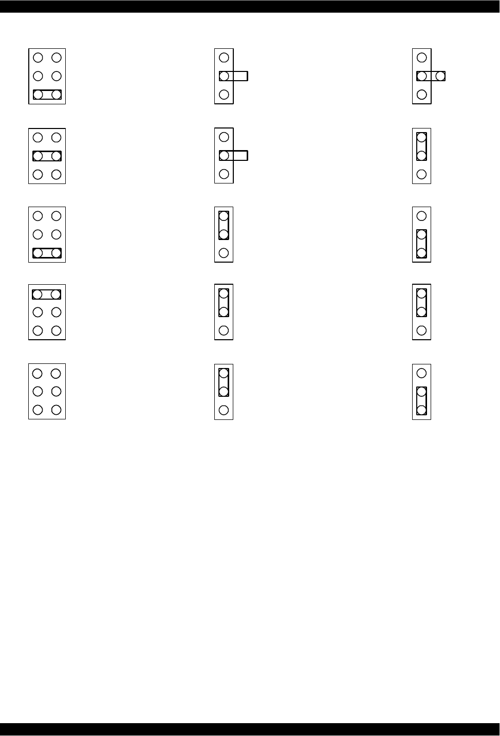
J8 Clock Source J10 Reference I/O J11
Standard Oscillator No I/O
TCXO No I/O
Standard Oscillator Standard Oscillator Out
TCXO TCXO Out
External Reference In External Reference In
Note: * Indicates Factory Setting
** *

Radio Systems, Inc. TR-6000 Manual
4/01 Page 6
TR-6000 Frequency Change Procedure
1. Set dip switches S1, S2 and S3 for the desired output frequency.
2. Set the output filter jumpers for low or high band.
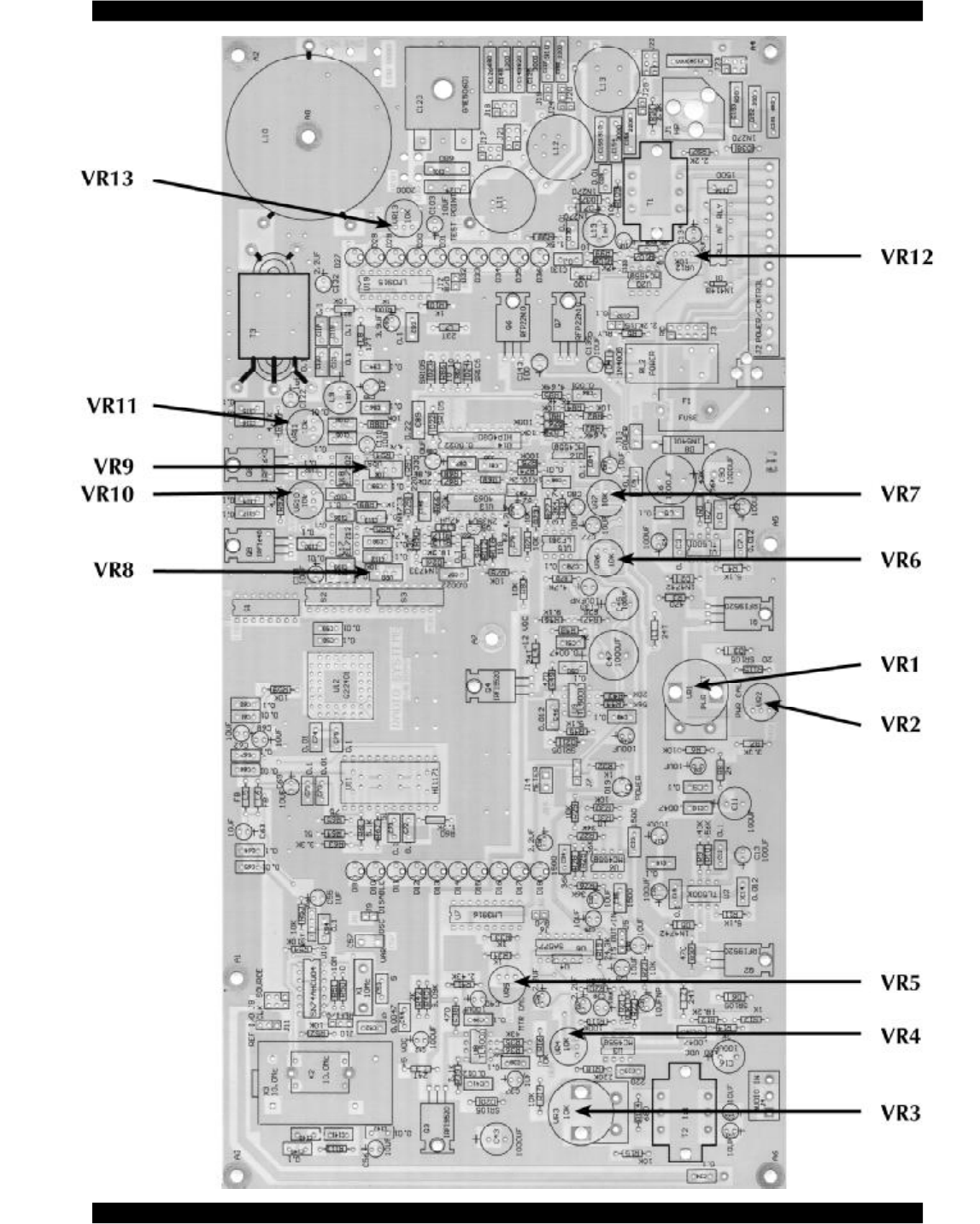
3. Adjust the power control VR1 to its minimum position.
4. Turn VR10 and VR11 fully counter clockwise.
5. Apply power to the unit.
6. Measure the oscillator frequency at U11 pin 13.
7. Adjust C57 for an oscillator frequency of 10 MHz.
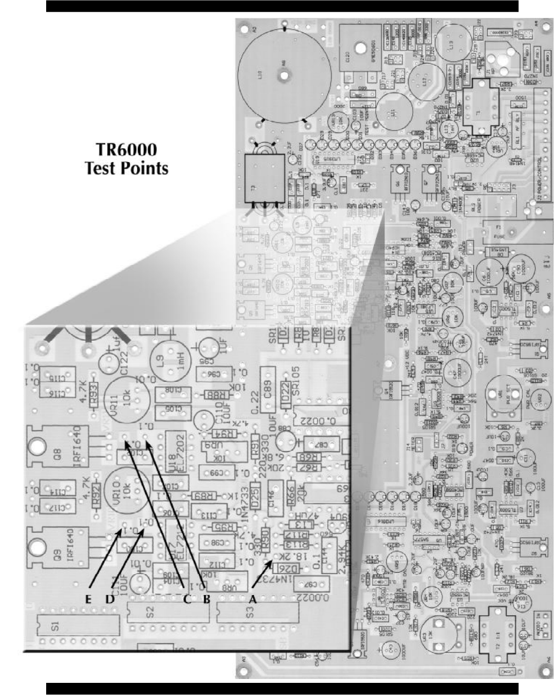
8. Check for the carrier frequency (Test Point A).
9. Adjust VR8 for a 45% duty cycle square wave at U17 pin 5 (Test Point D).
10. Adjust VR9 for a 45% duty cycle square wave at U18 pin 5 (Test Point B).
11. Adjust VR1 for 10 volts on the drain of Q6.
12. Adjust VR7 for 5 volts on the center tap of T3.
13. Adjust C123 for maximum power output.
14. Increase VR10 and VR11 until the bottom half the gates signals of Q8 and Q9 are just below
zero volts (Test Point C & E).
15. Increase VR1 to its maximum position and adjust VR2 for the desired maximum power (Not to
exceed 10 watts).
16. Calibrate the RF power meter with VR13.
17. Apply a -50 dBm, 1 KHz audio signal to J4 +/-.
18. Adjust VR3 fully clockwise.
19. Adjust VR4 for maximum modulation.
20. Turn VR3 counter clockwise to reduce the modulation percentage and re-adjust VR4 for
maximum modulation.
21. Increase the audio generator level to 0 dBm and adjust VR3 to the point just below clipping of
the RF envelope.
22. Adjust VR6 for 90% to 95% modulation.
23. Check the audio frequency response, carrier frequency and RF spectral purity of the unit.
24. Decrease the audio generator level in 10 dB steps and check for at least approximately 80%
modulation down to a -35 dBm level.
25. Calibrate the VU meter to 0 with VR5.
26. Check the carrier frequency and RF spectral purity of the unit.
27. Seal all potentiometers except VR1, VR3 and VR12.
28. Install the top cover.
29. Turn the unit on and re-adjust C123 for maximum power output.

Radio Systems, Inc. TR-6000 Manual
4/01 Page 7
TR-6000 Test Procedure
1. Check the circuit board for solder shorts and bad solder joints.
2. Check the alignment of the terminal strips, headphone jack and potentiometers.
3. Check for proper installation of diodes, transistors and IC’s.
4. Set all potentiometers except VR10 and VR11 to their center position.
5. Set potentiometers VR10 and VR11 fully counter clockwise.
6. Install a jumper on J7 for “power LED independent of metering.”
7. Install a jumper on J5 for “TIS filter disabled.”
8. Install a power jumper on J13.
9. Remove U12.
10. Set dip switches S1, S2 and S3 for the desired output frequency.
11. Apply power to the unit and check for the power LED to illuminate.
12. Check the output of the variable regulator, twenty volt regulator, twelve volt regulator and the five
volt regulator.
13. Install jumpers J8, J10, and J11 for “standard oscillator” and “no I/O.”
14. Measure the oscillator frequency at U11 pin 13.
15. Adjust C57 for an oscillator frequency of 10 MHz.
16. Turn off the power and install U12.
17. Connect an RF load to the RF output.
18. Power up the unit and check Test Point A for the carrier frequency (riding on a 5 volt DC level).
19. Adjust VR8 for a 45% duty cycle square wave at Test Point D.
20. Adjust VR9 for a 45% duty cycle square wave at Test Point B.
21. Adjust VR1 for 10 volts on the drain of Q6.
22. Adjust VR7 for 5 volts on the center tap of T3. (Should be 1/2 of Q6 VDD. A lower reading
improves unit distortion; a higher reading increases power output for a given Q6 VDD.)
23. Adjust C123 for maximum power output.
24. Increase VR10 and VR11 until the bottom half the gate signals of Q8 and Q9 are just below 0
volts (Test Points C & E).
25. Increase VR1 to its maximum position and adjust VR2 for the desired maximum power (not to
exceed 30 watts).
26. Install a power jumper on J14 and calibrate the RF power meter with VR13.
27. Apply a -50 dBm, 1 KHz audio signal to J4 +/-.
28. Adjust VR3 fully clockwise.
29. Adjust VR4 for maximum modulation.
30. Turn VR3 counter clockwise to reduce modulation percentage and readjust VR4 for maximum
modulation.

Radio Systems, Inc. TR-6000 Manual
4/01 Page 8
31. Increase the audio generator level to 0 dBm and adjust VR3 to the point just below clipping of
the RF envelope.
32. Adjust VR6 for 90% to 95% modulation.
33. Decrease the audio generator level in 10 dB steps and check for at least approximately 80%
modulation down to a -35% dBm level.
34. Calibrate the VU meter to 0 with VR5.
35. Check the monitor audio output and switched monitor audio output.
36. Check the power control relay.
37. Check the headphone jack.
38. Check the audio frequency response to 10 KHz.
39. Enable the TIS filter by moving the J5 jumper.
40. Re-adjust VR6 for 90 % modulation with 1 KHz, 0 dBm audio input.
41. Check the audio frequency to 10 KHz ( <= 2% modulation at 10 KHz).
42. Check the carrier frequency and RF spectral purity of the unit.
43. Seal all potentiometers except VR1, VR3 and VR12.
44. Install the circuit board in the chassis and install the top cover.
45. Turn the unit on and re-adjust C123 for maximum power output.
46. Write the date, output frequency, TIS or Non TIS and output on a “TESTED” sticker and place it
over the C123 adjustment hole on the bottom of the unit.
Radio Systems, Inc. TR-6000 Manual
4/01 Page 9
Radio Systems, Inc. TR-6000 Manual
4/01 Page 10
Radio Systems, Inc. TR-6000 Manual
4/01 Page 11
Radio Systems, Inc. TR-6000 Manual
4/01 Page 12
B
Radio Systems, Inc. TR-6000 Manual
4/01 Page 13
Radio Systems, Inc. TR-6000 Manual
4/01 Page 14

Radio Systems, Inc. TR-6000 Manual
4/01 Page 15
TIS High Quality Audio Processor 5.1 Installation Instructions.
Installation and Wiring
1. Turn off the AC power by turning off the switch on the AC Power Strip.
2. Install the Audio Processor in a suitable location in the back side of your rack. Rack
screws are provided.
3. Remove the wire from the Isolation Transformers Input terminals.
4. Splice one of the provided wires to the wire you just removed from the Isolation
Transformer using the provided UY Butt Splices. Squeeze the UY Butt Splices with a
pliers to make the connections.
5. Terminate the same wire to the Audio Input terminals on the back of the Audio
Processor. Spade terminals are included.
6. Install the second provided wire from the Audio Output terminals on the rear of the Audio
Processor to the Audio Input terminals on the Isolation Transformer.
7. Install the in AC Input cable.
8. Restore AC power.
Adjustment Procedure
1. Move the Power, Peak Limiting, Pre-Emphasis and Lowpass Function switches on the
Audio Processor to the ON position.
2. Adjust the audio output level of the NX8R to 80 by using the control phone in the cabinet
with the following commands:
a. Press
to gain access to the “Create a Playlist” command.
b. Press
to select all outputs.
c. Press
to set the output level to 80.
3. Adjust the Input Gain setting on the Audio Processor such that the Limiter G/R 0, -2 and
-6 LEDs are flashing regularly but the -12 LED only flashes occasionally, if at all. This
step was already taken at the factory but some fine adjustment may be necessary.
4. No adjustment of the Output Level or Pos Peaks pots will be required.
5. While monitoring the AM broadcast on a car radio, adjust the Transmitter’s Mod Adjust
knob to the point where the audio is as loud as possible without distorting.
6. In normal operation the Hi Freq. G/R LEDs will all flash regularly as will the Filter O.S.
Comp LED.
TIS 5K Audio Filter Installation Instructions.
Installation and Wiring
1. Turn off the AC power by turning off the switch on the AC Power Strip.
2. Install the Audio Processor in a suitable location in your rack. Rack screws are provided.
3. Remove Wire #3 from the Audio Input terminal strip on the top of the transmitter with a
small flat blade screwdriver.
4. Terminate wire #3 to the Audio Input terminals on the TIS Filter. Spade terminals are
included.
5. Install the included wire #11 from the Audio Output terminals to the Audio Input terminals
on the top of the transmitter.
6. Restore AC power.
Modulation Adjustment Procedure
1. Adjust the “Mod Adjust” modulation knob on the TR6000 transmitter until the Audio VU
LEDs on the face of the transmitter peak at 0dB. Monitor the signal in your vehicle or
with a handheld receiver to make sure that the signal is not over-modulated and
distorted.

Radio Systems, Inc. TR-6000 Manual
4/01 Page 32
Warranty
Radio Systems, Inc. warrants this equipment to be free from defects in materials and workmanship for a
period of one (1) year.
This warranty extends to first users of the product and future owners who purchase this product within the warranty
period.
The terms of this warranty are null and void if this product is stored or operated in an enviroment not conducive to
electronic equipment, or shows signs of misuse or modifications, which affect the proper functioning of the product.
This warranty does not apply to damage caused by fire, smoke, flood, lightning,or acts of nature and physical abuse.
Radio Systems, Inc., and its associated companies, authorized distributors, and personnel are not liable for
loss of revenues or other damages, or effects to the broadcast signal quality or coverage which may result
from the improper functioning of this product.
Repair Policy
Technical assistance is available at any time, at no charge, by phone or correspondence.
During the warranty period, there will be no charge for parts or service made to units which show no sign of
misuse by customer or lightning caused damage. The customer is responsible for the cost of shipping their
unit back to Radio Systems for repair.
During the warranty period, shipment of small parts and assemblies may also be made at a charge to the
user. Emergency shipments of replacement parts and circuits will be made at the user’s request for an
extra shipping and service charge. Chargeable services will be made COD or on Net-30 day terms to users
with established accounts.
During the warranty period, full credit or return of COD charges (less any service and expedited shipping
charges) will be made to users who return the defective parts or circuits within 30 days, if the damage is
covered under the terms of the warranty.
Return Instructions
Contact Radio Systems (856-467-8000) for a return authorization number.
Pack all items carefully and ship prepaid, via UPS insured, to:
Radio Systems, Inc.
Attn: R.A. # ____________
601 Heron Drive
Logan Township, NJ 08085
Enclose a note that includes your name, company, phone number, the serial number, return address (no
box numbers), and a complete description of the problem.
FCC INFORMATION
FCC ID: B7MTR-6000TIS-WB
THIS DEVICE COMPLIES WITH PART 15 and 90 OF THE FCC RULES. OPERATION IS SUBJECT TO THE
FOLLOWING TWO CONDITIONS. (1) THIS DEVICE MAY NOT CAUSE HARMFUL INTERFERENCE, AND (2)
THIS DEVICE MUST ACCEPT ANY INTERFERENCE RECEIVED, INCLUDING INTERFERENCE THAT MAY CAUSE
UNDESIRED OPERATION.
WARNING: CHANGES OR MODIFICATIONS NOT EXPRESSLY APPROVED BY THE PARTY RESPONSIBLE FOR
COMPLIANCE COULD VOID THE USER’S AUTHORITY TO OPERATE THIS EQUIPMENT.

For Assy:
Part #11234
2/06
601 Heron Drive
Logan Township, NJ 08085
Phone: 856-467-8000 Fax: 856-467-3044
http://www.radiosystems.com