Ingenico Barcelona I3070CTL PAYMENT TERMINAL User Manual USERS MANUAL
Ingenico Barcelona S.A. PAYMENT TERMINAL USERS MANUAL
USERS MANUAL

1
Ingenico
3070
Contactless
User guide
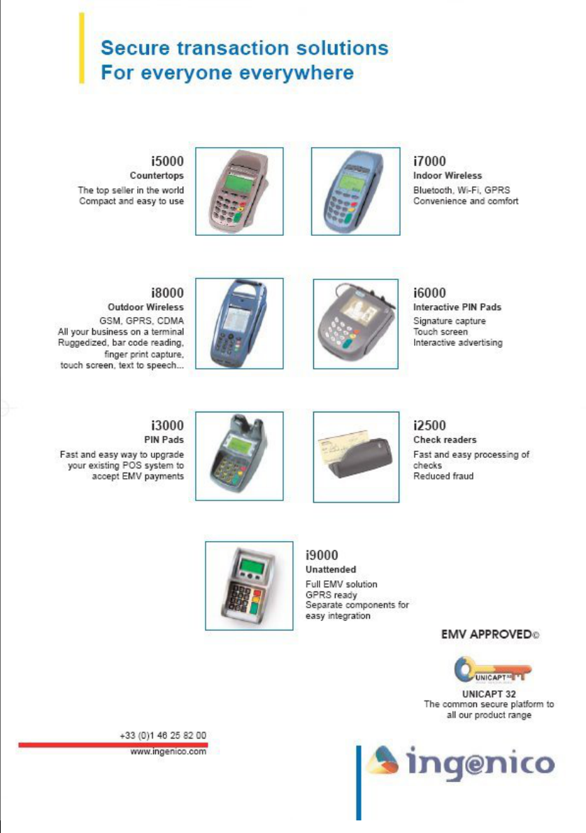
Secure transaction and payment solutions

3
Contents
1 Presentation ..................................................................................................5
1.1 Overview of Ingenico 3070 ....................................................................6
1.2 Keyboard details and functionality .........................................................7
2 Use..................................................................................................................9
2.1 Card reading..........................................................................................9
2.2 Contactless reading ...............................................................................9
2.3 SIM interface........................................................................................10
2.4 Optionnal privacy shroud .....................................................................11
2.5 Installing the cable securing plate........................................................11
2.6 Terminal maintenance .........................................................................12
3 Installation and starting..............................................................................13
3.1 Location of the terminal .......................................................................13
3.2 Terminal connections...........................................................................14
3.3 Turning on the terminal........................................................................15
4 Recommendations......................................................................................17
5 If you experience problems........................................................................19

Ingenico 3070 Contactless
4
5
1 Presentation
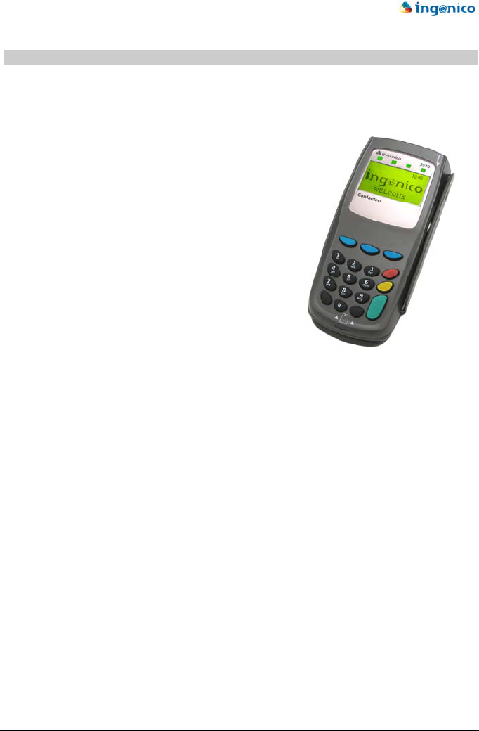
The Ingenico 3070 is a compact PIN-pad designed to accept all kinds of payment using
Contactless, magnetic and smart cards and able to be use as handheld or countertop device.
It has the following features:
Keyboard of 18 keys (15 + 3 function keys).
Graphic LCD backlight display (128 x 64).
Smart Card reader.
Magnetic stripe reader.
Contactless reader
RS232 Interface.
USB Interface (Option).
The terminal box contains:
the terminal,
this manual
An optional removable privacy shroud.
Ingenico 3070 Contactless
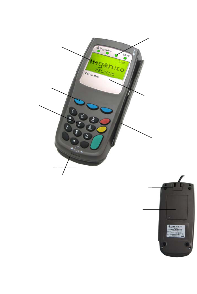
1.1 Overview of Ingenico 3070
The Ingenico 3070 is a very compact and light hand-held PIN Pad for Contactless migration.
6
Contactless reader
Magnetic stripe reader
Graphic display with Backlight
Keyboard
Functions keys
Contactless LED
Smart card reader
Dimensions: H: 40mm x W: 80mm x D: 170mm
SIMs compartment
Connection plug with
cable securing plate
Weight: 306 g (without cable)
7
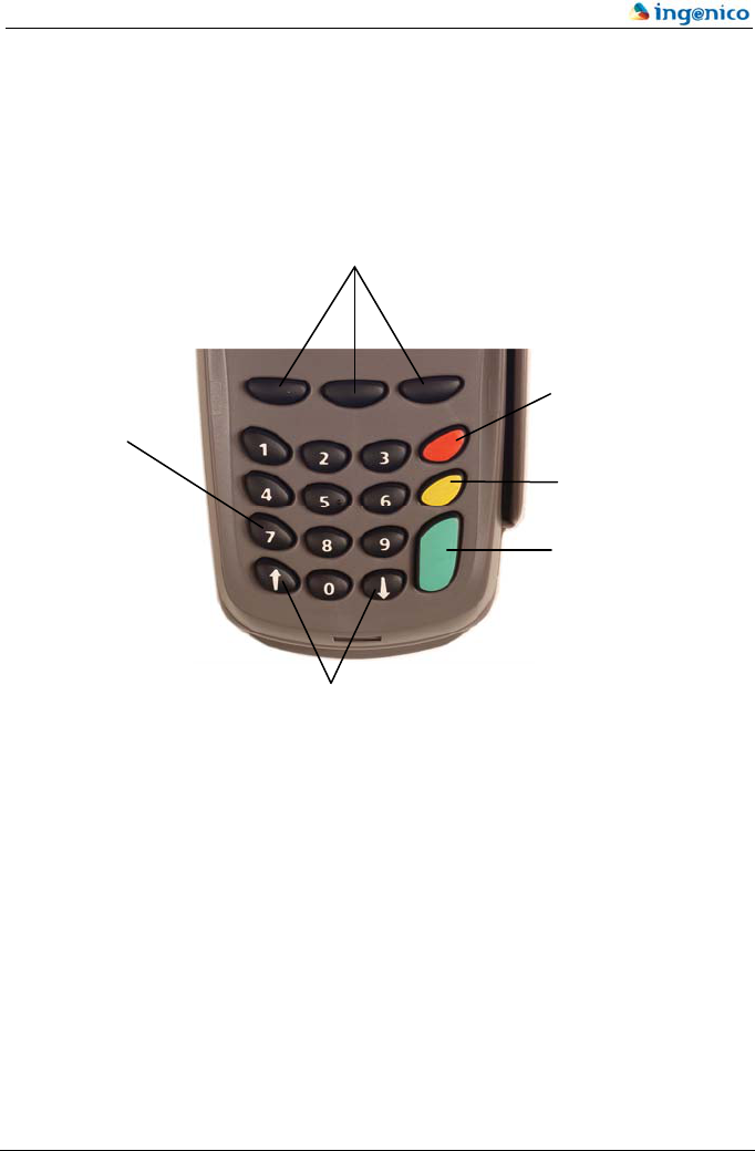
1.2 Keyboard details and functionality
This chapter describes the key functions for a terminal with no specific application. Some
keys can have other functions according to the applications that are present in the terminal.
The 3 programmable function keys will have differen
t
utilities according to the application installed in the
terminal
The red key cancels the
procedure in progress
Alpha digital keys
The yellow key clears the
last character
The green key validates
the input selections an
d
information
Programmable keys which have
different functions according the
application installed in the terminal

Ingenico 3070 Contactless
8
9
2 Use
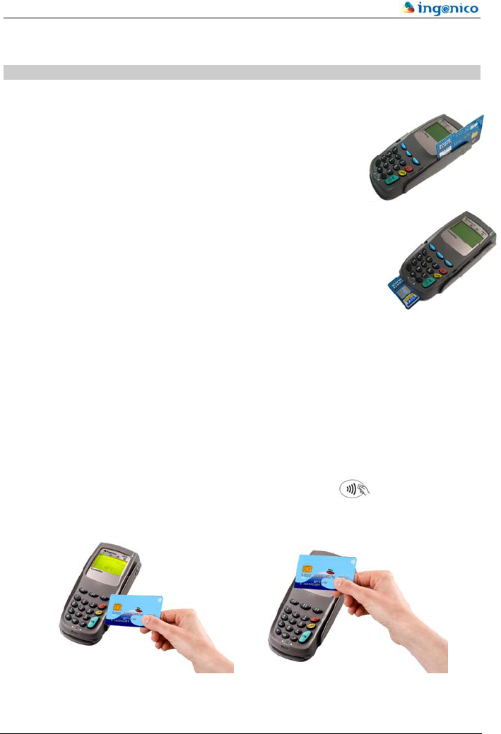
2.1 Card reading
Magnetic stripe card
The card can be read either from bottom to top or from top to
bottom, with the stripe facing the terminal. Use a regular movement
in order to ensure a reliable card reading.
Smart card
Insert the card horizontally with the metal chip facing upwards, slide
the card until the top and leave in position throughout the transaction.
2.2 Contactless reading
Your terminal features an integrated contactless reader.
To perform a contactless payment transaction, you will need an application capable of
accepting contactless payment already loaded in the terminal, and a contactless smart card
that is compatible with that application.
A green light on the left side of the antenna head indicates the terminal is ready to accept a
contactless card.
) Hold the contactless smart card close to the contactless logo until you see a series
of green lights illuminate.
Figures 2
Figures 1
Ingenico 3070 Contactless
10
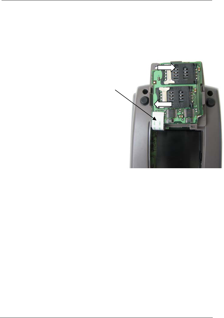
2.3 SIM interface
There are up to 3 internal Sims connectors, accessible once the protection cover has been
removed.
0 The terminal must be powered off while inserting or removing SIM!
Installing a SIM card OPEN
) Remove the cover,
0 Pay attention not to disconnect the flat
cable connected to the PIN-pad!
) Unlock the connector by sliding the metallic
part in the direction of the OPEN arrow,
LOCK
) Lift the card housing up,
) Insert a SIM card into the housing,
0 Make sure you put it in the right way,
follow the foolproof lug!
) Put the housing back down again,
) Lock the connector by sliding the metallic part in the direction of the LOCK arrow.

11
2.4 Optionnal privacy shroud
One optionnal removable privacy shroud could be added only if your terminal have the two
side holes inside provided.
) Insert the two small plugs of the privacy shroud in the 2 holes of the terminal and press
strongly to fix the privacy shroud.
The 2 holes
The 2 plugs
2.5 Installing the cable securing plate
Your terminal features a removable securing plate.
) To install the securing plate, insert it vertically and toward you, then press it to the
terminal until you hear a “click”.
) To remove the securing plate, squeeze the two securing tabs and draw it upwards.

Ingenico 3070 Contactless
12
2.6 Terminal maintenance
The following points should be observed to ensure correct function of the terminal:
Avoid lengthy exposure to direct sunlight.
Avoid cleaning the terminal with abrasive substances, solvents, aggressive products
or excessive moisture.
Do not clean the reader heads with abrasive or aggressive substances or solvents
(the technical service department has cleaning cards available).
Do not enter any element in the smart cards compartment, only the cards for which
it has been homologated in this PIN pad.
Only authorised personnel may load software into the terminal.
There are no user replaceable parts in the terminal. Should a product become faulty
it is intended that a replacement unit is installed and the faulty unit is returned to a
suitable service centre for repair or disposal.
Do not push the keys with excessive force.

13
3 Installation and starting
3.1 Location of the terminal
The terminal should be placed in such a way that the user has easy and simple access
without forcing its cables or equipment connections.
For reliable operation of the contactless reader consideration must be made of the following:
• the location of in-store RFID anti-theft devices. (Visa report that transactions can
be disrupted when the readers are within 2m (6 feet) of an RFID anti-theft device).
• the proximity of other contactless card readers. The recommended minimum
spacing between adjacent readers should be at least 30cm (12 inches).
• the proximity of other transmitting devices (for example: mobile phones, personal
digital assistants, pagers, etc.).
• the susceptibility of contactless card readers to electromagnetic interference ( for
example: switching of inductive loads, inadequately grounded electrical
equipment, etc…)
• the proximity of metallic material between the reader and a contactless card.
Operating Temperature
+0 to +40°C
Humidity
5% to 90% RH non condensing
Storage temperature
0°C to +60°C
0 The product is designed for indoor use only. Before using the terminal in
a motor vehicle assess the suitability due to the inherent electrical noise
and interference present in such an environment.
Ingenico 3070 Contactless
14
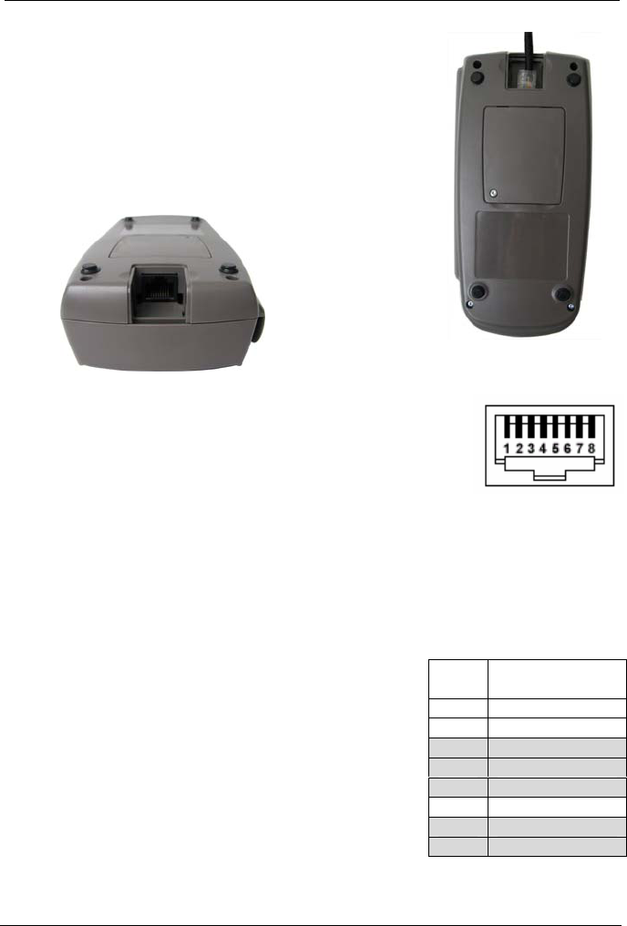
3.2 Terminal connections
Ingenico 3070 can be connected in a number of configurations:
Through a cash register by USB or RS232,
To another terminal by RS232 or USB.
All the connections are done via the socket on the rear of the unit.
The PINPAD is connected to the terminal by means of a male
RJ45-8 connector for RS232, USB.
Power requirements
The device has to be powered by the host device where it is connected (Terminal, PC, ECR,
etc.). It will draw power via the serial port cable.
Power requirements (RS232, USB SELF-POWERED) are 7 – 18 VDC / 0,4A.
For USB Bus Powered is 5VDC / 0,5A.
For Ethernet is 5VDC / 0,45A.
RJ45
PIN
RS232
1 ------
2 ------
3 ------
4 GND
5 7-18V
6 RX
7 TX
8 ------
RS-232
Powered RS232 serial port.
Signals: TxD, RxD, VCC and GND.
Maximum port baud rate 115.200.
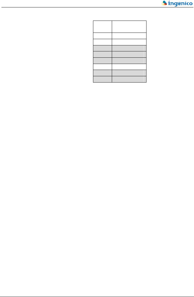
USB + RS232 RJ45
PIN USB
+ RS232
1 +5V USB
2 D-
3 D+
4 GND
5 7-18V
6 RX
7 TX
8 ------
Powered USB High Power port.
Signals: D+, D-, Vbus and GND.
0 Before connecting or disconnecting the communication cable for either
machine, both must be turned off (first the terminal and the PIN pad after).
3.3 Turning on the terminal
) Connect the correct cable to the terminal.
The sequence the terminal will follow during the start-up is as follows:
1. Connection.
2. Auto-test. The terminal checks the correct function of all of its elements comprising it as
well as the integrity of the stored data and programs. During this auto-checking process it is
important do not to press any key because it could cause the detection of a keypad anomaly.
15

Ingenico 3070 Contactless
16

17
4 Recommendations
Safety
Tasks to be done by the installer
As this is a secure PIN device Ingenico advice you to make the following checks prior to
installing your PIN-pad and thereafter on a daily basis:
Checking PIN-pad integrity
(1) Check that there is NO external damage to the plastic housing; particularly around the
keyboard, display and reader areas.
(2) Ensure that there are NO additional cables protruding from the PIN-pad; there should
only be a single cable from the rear of the PIN-pad.
(3) There should be NO holes drilled into any area of the housing.
Selecting the place where the PIN-pad is installed
(4) Ensure that there are NO security cameras focusing the PIN-pad.
(5) Ensure that there are NO close objects where a camera can be hidden.
(6) Ensure that the PIN-pad can NOT be observed from outside (any window or door)
during PIN entry.
Necessary warning for customers
(7) Ensure “wait your turn” sticker is placed to a place where clients in queue can’t observe
the keyboard while the PIN entry.
(8) An advertisement must be placed near the terminal. This advertisement must be visible
for the customers before the PIN entry. The advertisement must indicate (textual and
graphically):
how to protect the PIN entry from other customers and the cashier (using the hand
not used for the PIN entry if necessary)
that integrity of the PIN-pad must be checked
Smart card reader must be on the side of the customer while PIN entry.
Training cashiers
(9) Installer must train cashiers to check integrity of terminal on a daily basis (all the points
in 0 and 0).
(10) Installer must train cashiers to encourage customers to respect “wait your turn” sticker.
As this terminal does not have a power off switch, the disconnecting device is the main
transformer; the power supply plug must therefore be easily accessible.
Ingenico 3070 Contactless
Safety directives concerning the Lithium batteries
Keep out of the reach of children.
If any elements of the batteries are swallowed, the person should consult a doctor
or seek medical assistance immediately.
It is important to comply with the "+" and "–" polarities.
Do not try to reactivate the batteries using a heat source, an electric recharge or any
other means.
Do not throw the batteries into the fire.
Do not dismantle the batteries.
Generally speaking
There is a danger of explosion if the batteries are not replaced correctly.
Replace the batteries with same type elements or similar type elements
recommended by the manufacturer only.
Dispose of used batteries in compliance with manufacturer instructions.
Do not throw the batteries into the bin; dispose of them in suitable recycling
facilities.
WEEE
This symbol on the product or on its packaging means that this product should
not be treated as household waste.
To minimise environmental impacts and the disposal of waste, this product should be
handed over to a separate collection system in order to facilitate recycling and recovery.
For more detailed information, please contact your reseller.
18

5 If you experience problems
Call one of the customer service centers listed below:
In Canada In the USA
TotalCARE
6520 Gottardo Court
Mississauga, Ontario
L5T 2A2
1-888-900-8221 (905-795-8221)
Ingenico Inc
TotalCARE
1003 Mansell Road
Atlanta, GA 30076
1-800-435-3014 (770-594-6000)
.
This equipment has been tested and found to comply with the limits for a Class B digital
device, pursuant to part 15 of the FCC Rules. These limits are designed to provide
reasonable protection against harmful interference in a residential installation.
This equipment generates, uses and can radiate radio frequency energy and, if not installed
and used in accordance with the instructions, may cause harmful interference to radio
communications. However, there is no guarantee that interference will not occur in a
particular installation. If this equipment does cause harmful interference to radio or
television reception, which can be determined by turning the equipment off and on, the user
is encouraged to try to correct the interference by one or more of the following measures:
—Reorient or relocate the receiving antenna.
—Increase the separation between the equipment and receiver.
—Connect the equipment into an outlet on a circuit different from that to which the receiver
is connected.
—Consult the dealer or an experienced radio/ TV technician for help.
Changes or modifications not expressly approved by Ingenico could void the user’s
authority to operate the equipment.

DIV1256A
Your contact
Ingenico
192 avenue Charles de Gaulle
92200 Neuilly sur Seine France
Tel. : +33 1 46 25 82 00 – Fax : +33 1 47 72 56 95
www.ingenico.com