Ingenico Barcelona I7810 WIFI, Terminal of Payment User Manual
Ingenico Barcelona S.A. WIFI, Terminal of Payment
users manual
1. Ingenico i7810 description:
The i7810 is a portable, wireless Wi-Fi point of sale
electronic payment terminal designed to process debit,
credit and smart card purchases. It is highly secured,
EMV level 1 and 2 certified. The i7810 enables perfect
integration of the payment system into the WLAN.
The i7810 provides fast service, long life battery,
convenience, flexibility and security powered by
Ingenico’s High Security Core and UNICAPT™. The
Wi-Fi communications are fully protected by 128-WEP
or WPA security. I7810 includes large graphic display
and easy loading printer.
Various peripherals can be connected to i7810 or its base.
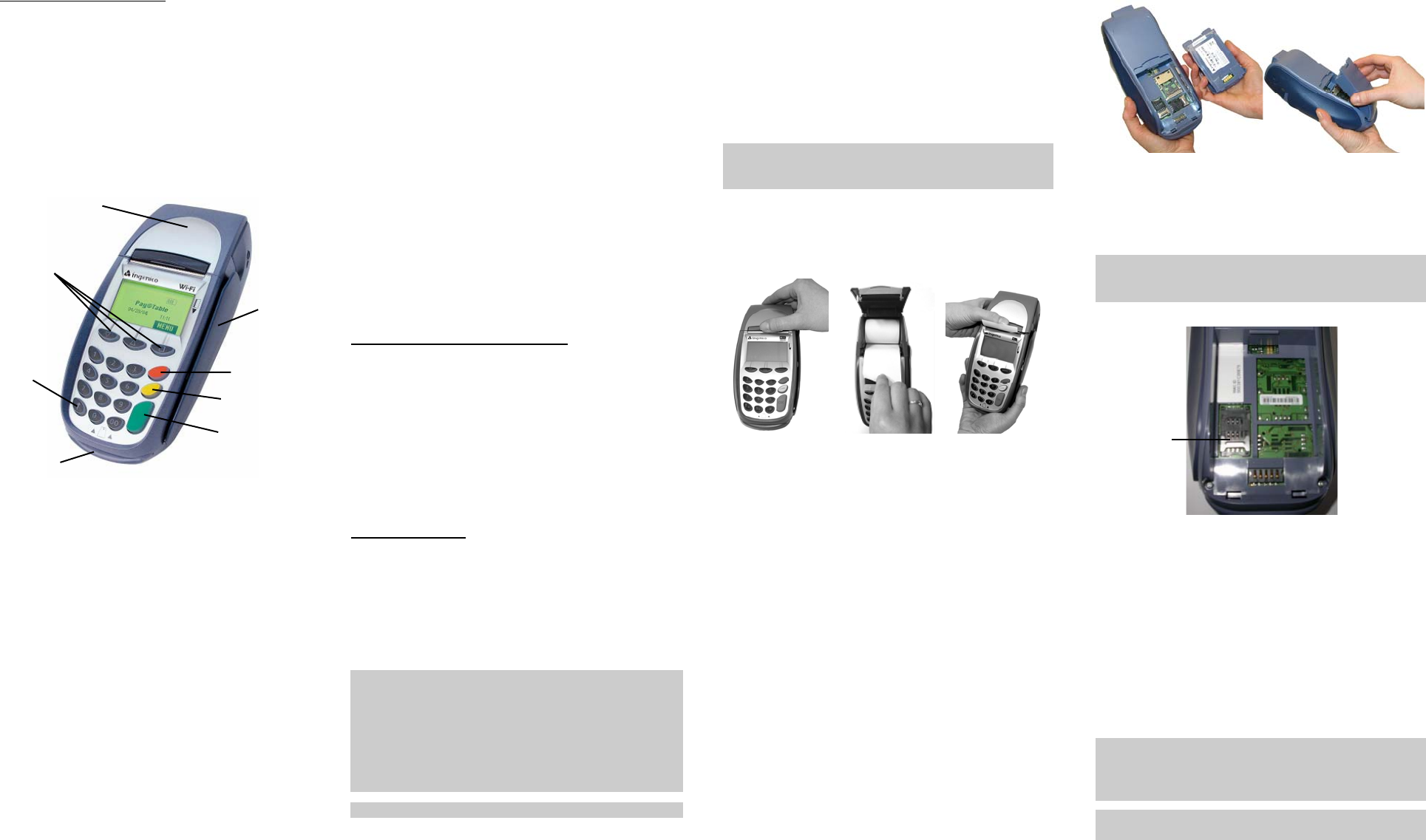
1.1. Display:
A 4 line x 16 character LCD graphic display, with a
back light.
1.2. Keypad:
18 keys, with a back light. The special function keys are:
• Programmable function keys <F1>, <F2> and <F3> for
navigation and access to various i7810 functions and
the system and application menus.
• Paper Feed key is used for a printer paper feed (a few
cm).
• The green <ENTER> key confirms the data entered or
displayed. It also powers on the i7810.
• The red <CAN> key cancels the current function and
returns the terminal to the idle state. It also powers off
the i7810 if it is not connected to the power supply (it
depends of the application running on i7810).
• The yellow <CORR> key corrects invalid data entry.
• The blue <ADMIN> key is used to access the terminal
administration function menu.
1.3. Magnetic Stripe Card Reader:
The i7810 features a bi-directional, 3-track reader located
on the right-hand side. The card can be swiped from the
bottom to the top, or from the top to the bottom. The
magnetic stripe on the card has to face down and point
toward the keypad. The card has to be swiped at uniform
speed and pressure, ensuring that the card remains in contact
with the bottom of the track throughout the entire swipe
action.
1.4. Smart Card Reader:
Insert the smart card horizontally into the slot on the front of
the i7810, the microchip facing up, and leave it in the reader
throughout the transaction.
The i7810 has EMV level 1&2 approvals and complies
with the ISO 7816, Sync and Async T=1 & T=0.
1.5. Printer:
The i7810 integrates a quiet, high speed, “easy-load” style
thermal printer with graphics capability.
1.6. Battery:
Rechargeable and easily replaceable Li-Ion battery pack.
1.7. SAM Connectors:
SAM card connector is located underneath the i7810 battery.
The SAM (Secure Access Module) supports smart card
chips necessary for applications such as loyalty.
2. Ingenico 7810 Packaging Content:
1. i7810 terminal.
2. Li-Ion battery pack.
3. Thermal printer paper, one roll.
4. The base (dial or charging only).
5. The cable securing plate and a screw.
6. Power supply for battery charging.
7. LinkBox (optional).
8. Phone cable (optional).
9. ComBox (optional).
10. This installation guide.
3. i7810 Installation:
Place the base on a clear, flat surface near an electrical and
telephone sockets (for an optional back-up dial connection).
The i7810 hand-held and the base must be protected from
high temperature, vibrations, dust, dampness and
electromagnetic radiation (computer screen, microwave
oven, anti-theft barrier etc.). Equipment such as cordless
phones, cellular phones and Bluetooth devices can emit
harmonics that could disturb the terminal at 2.45 GHz.
Avoid using i7810 near a great vertical metal plane (doors of
refrigerator, large home appliances, vending machines), they
reduce the working range.
Ensure the base or the terminal is more than 3 m (around 10
feet) from any microwave oven in use.
Do not place i7810 on a metal surface.
Do not put your hand under the printer during
communication as the range is greatly reduced.
Ensure that the terminal is seated securely on the base.
Before terminal can be used, the paper roll has to be installed
and the battery has to be fully charged.
Operating temperature ................................ +5°C to +40°C
Humidity .........................20% to 90% without condensation
Storage temperature .................................... -10°C to +60°C
3.1. Installing/Replacing the Printer Paper
When the coloured stripe on the paper appears, replace the
paper:
Turn OFF the i7810 before replacing paper roll.
DO NOT touch the printer parts, they can be very hot. Be
aware of the sharp paper cutter.
1. Push the button on the paper compartment cover toward
the back and lift the cover.
2. Remove the empty paper roll and insert the new roll.
Ensure that the paper is protruding from UNDERNEATH
the paper roll:
3. Close the cover, press it until it snaps. Press the “Paper
feed” key to verify that paper feeds properly.
Thermal Paper Specification:
• Single ply thermal sensitive – POS or facsimile grade.
• Basis Weight: (lb/rm 17 ins. X 22 ins. - 500) --- 14.5 ± 5%
(GSM) --- 55 ± 5%
• Caliper.............................2.4 ± 0.2 Mils or 60 ± 5 Microns
• Brightness ...........................................................Min. 85%
• Smoothness (Bekk Minimum) ...................................300 s
• Roll Width....................2.28 ± 0.040 in (58 mm ± 1.0 mm)
• Roll Diameter...........................1.97 in (50 mm) maximum
• Roll Core ID..............................0.500 in (13 mm) nominal
• Roll Core OD............................0.625 in (16 mm) nominal
Recommended brands:
KANZAN............... KF50 JUJO ..............AF50KS-E
KOEHLER.... KT55HS01 MITSUBISHI ....... P6402
Thermal paper should NOT be exposed to vinyl, plastics,
adhesives, shrink-wraps, wet-toner copies or certain carbon
papers, office light UV light, high humidity and temperature
(above 65%, 25°C or 77°F) for long periods of time.
3.2. Installing the Battery
Hold the battery as shown, connectors facing downwards.
Do not touch connectors on the battery or on the i7810.
Insert the two plastic teeth in the gaps on the i7810 case,
place the battery into the cavity and push it. Press the battery
handle until a click is heard.
3.3. Installing the SAM Card
The SAM card connector is located underneath the battery
pack.
Make sure that i7810 is turned off before handling the
battery pack. Do not touch the contacts on the battery pack
or on the i7810.
• Remove the battery pack.
• Unlock the SAM connector by sliding the metallic latch
in the direction of the OPEN arrow.
• Lift the SAM cover upward and insert the SAM card.
• Swing the cover down and slide the latch into locked
position (the LOCK arrow).
• Put the battery back in the i7810 handheld.
Follow these instructions in reverse order to remove SAM
card.
3.4. Charging the Battery:
The i7810 comes with a light, easily removable and
rechargeable lithium-ion battery. Only use the battery
supplied with your terminal.
Do not remove battery from i7810 unless installing or
removing SAM card. Make sure that i7810 is turned off
before handling the battery pack. Do not touch the contacts
on the battery pack or on the i7810.
Always charge the battery at the room temperature.
It is important to perform the full battery charge before using
Navigation keys
Printer
CANCEL
Key
CORR Key
ENTER Key
Paper
Feed Key
Magnetic
Stripe Card
Reader
Smart Card
Reader
SAM
connector
i7810 for the first time – charge the battery without
interruptions until i7810 terminal indicates the end of
charging process (no moving bars on the battery status
icon).
To charge the battery:
Place i7810 on the base (the base must be powered up).
Do not place battery on the base by itself, the battery
must be charged while installed in i7810.
Ensure that the hand-held is seated securely on the base.
Use the power adapter supplied with i7810. Many
adapters can appear similar and will plug into the base
but will not work properly causing erratic behavior, poor
charging or even damage to the unit.
The i7810 with a fully charged battery can perform up to
200 transactions (depending of the ticket size,
transaction duration, time between transactions and
backlight usage).
The battery status is updated on the i7810 display (the
indicator depends of the application):
1 bar represents 25 % of full capacity,
2 bars represent 50 % of full capacity,
3 bars represent 75 % of full capacity,
4 bars represent full capacity.
Moving bars indicate that the battery is being charged.
3.5. Connections:
Turn the terminal off before connecting peripherals.
• Connections on the i7810 hand-held:
Connect LinkBox or ComBox to the RS-232 port, the
letters “TOP” on a connector must be facing up. The
green light (LinkBox only) indicates modem is ready.
The light becomes red while dial connection is used.
LinkBox provides dial connection (asynchronous and
synchronous, V22bis or V34) and powered RS-232
port. ComBox provides two RS-232 ports, one of them
powered (port marked RS232-2).
• Connections on the base:
Turn the base off when connecting peripherals. The
power supply must be connected last, only after all the
other connections are made.
DIAL LINE (not available on charge only base)
Plug the one end of a telephone cable (supplied with the
terminal) into the port marked , and connect the other
end of the cable to a wall telephone jack.
PHONE (not available on charge only base)
Plug one end of a telephone cable into the dial radio base
port labeled EXT LINE and plug the other end of the cable
in the phone.
RS-232 (not available on charge only base)
Unplug the base. Connect the serial cable to the port marked
COM2 or COM1/3. Plug the other end of the serial cable to
the device (PC, check reader etc.). For detailed instructions,
ask the equipment supplier.
POWER CONNECTION
Plug the power adapter radial jack into the base port marked
. The green light on the front right hand side of the
base indicates the power is on.
Attach the cable securing plate and fix it with a screw.
4. Normal Operation:
Depending of the application installed in the terminal, i7810
displays icons indicating:
• battery charge level,
• charging status and
• received signal strength.
Depending of the application, the i7810 terminal goes into
stand-by mode after a period of inactivity (in order to prolong
battery life). i7810 can be powered on by pressing the green
<OK> key, or by docking it on the base.
5. Technical specifications:
The i7810 communication is based on 802.11b standard,
protected by 128-WEP or WPA security.
Type...........................20 dBm hopping frequency
Bandwidth .................ISM 2.45 GHz
Emitting power..........≤ 100mW (20dBm)
Range.........................≈ 200 meters or 650 feet (open range)
The power supply:
• INPUT.................... AC 120V 60Hz
• OUTPUT..... DC 18V 0.9A 16.2VA
6. Cleaning procedure:
• The i7810 must be off for all cleaning operations.
• Do not clean the i7810 with water but with a dry or only
slightly damp cloth.
• Do not use solvent, detergent or abrasive products.
If the terminal has battery charge problem, clean the contacts
on the battery and on the terminal with a damp cloth.
Do not scratch or scrape the surface of the contacts.
• If the print quality deteriorates, clean the print head to
remove accumulated paper dust. The print head must be
cleaned with the terminal powered off, using ethanol
applied on a lint-free cloth.
Be aware of the sharp paper cutter and hot printer parts.
Ensure that the ethanol has completely evaporated before
switching the terminal back on.
7. If you experience problems:
Call one of the customer service centers listed below:
In Canada: In the USA:
TotalCARE Ingenico Inc.
6520 Gottardo Court TotalCARE
Mississauga, Ontario 1003 Mansell Road
L5T 2A2 Atlanta, GA 30076
1-888-900-8221 (905-795-8221) 1-800-435-3014 (770-594-6000)
This equipment has been tested and found to comply with the limits for a Class B digital device,
pursuant to Part 15 of the FCC Rules. These limits are designed to provide reasonable protection
against harmful interference in a residential installation. This equipment generates, uses and can
radiate radio frequency energy and, if not installed and used in accordance with the instructions,
may cause harmful interference to radio communications. However, there is no guarantee that
interference will not occur in a particular installation. If this equipment does cause harmful
interference to radio or television reception, which can be determined by turning the equipment off
and on, the user is encouraged to try to correct the interference by one or more of the following
measures:
. Reorient or relocate the receiving antenna.
. Increase the separation between the equipment and receiver.
. Connect the equipment into an outlet on a circuit different from that to which the receiver is
connected.
. Consult the dealer or an experienced radio/TV technician for help.
Ingenico is not responsible for any radio or TV interference caused by unauthorized modifications
to this equipment. Such modifications could void the user’s authority to operate the equipment.
RF Exposure Warning:
This equipment complies with FCC radiation exposure limits set forth for an uncontrolled
environment. This device must be operated with minimum 20 cm spacing between the antennas and
all person’s body (excluding extremities of hands, wrist and feet) during wireless mode of
operation. Further, this transmitter must not be co-located or operated in conjunction with any other
antenna or transmitter.
This device and its antenna must not be co-located or operating with any other antenna or
transmitter except Grant condition. Users are not permitted to modify this transmitter device. Any
unauthorized change made to this device could void your authority to operate this device.
Ingenico Inc.
1003 Mansell Road, Atlanta, GA 30076
Tel: (770) 594 – 6000 Fax: (770) 594 – 6003
www.ingenico-us.com
Ingenico Canada Ltd.
79 Torbarrie Road, Toronto, Ontario, Canada, M3L 1G5
Tel: (416) 245 – 6700 Fax: (416) 245 – 6701
www.ingenico-ca.com
Ingenico 7810
Installation Guide
DIV450011A
RS-2332
port