Ingenico BAS930P Base Unit for Payment Terminal User Manual User guide FCC updated 6
INGENICO Base Unit for Payment Terminal User guide FCC updated 6
Ingenico >
Manual
INGENICO – 192 avenue Charles de Gaulle – 92200 Neuilly sur Seine - FRANCE
Tél. 33(0)1 46 25 82 00 - Fax 33 (0)1 47 72 56 95
www.ingenico.com
EFT930 Wireless Series
U
s
e
r
G
u
i
d
e

EFT930 Wireless Series • 2/35
Copyright © 2009 Ingenico
9000001568 R11 000 02/941
All rights reserved
Contents
1. Introduction___________________________________________________ 4
2. Presentation __________________________________________________ 4
2.1. Content of the box ............................................................................................4
2.2. Overview of the EFT930 ............................................................................................ 5
2.3. Keyboard details and functionality ......................................................................................6
3. Use of the terminal_____________________________________________ 6
3.1. Adjusting contrast ............................................................................................6
3.2. Reading card ............................................................................................ 7
3.3. Switching off the terminal ............................................................................................8
3.4. Installing the terminal on the base.......................................................................................8
4. Installation ___________________________________________________ 9
4.1. Recommendations ............................................................................................9
4.2. Terminal connections ............................................................................................9
4.3. Installing Modules ...........................................................................................10
4.3.1. SAM1/SAM2 10
4.3.2. SAM3/SAM4 or SIM 10
4.3.1. MMC or SD Memory Card 11
4.4. Paper roll ...........................................................................................12
4.4.1. Mains characteristics of INGENICO paper roll 12
4.4.1. Installing paper roll 12
4.5. Battery ...........................................................................................14
4.5.1. Main characteristics 14
4.5.2. Installing the battery 14
4.5.3. Charging the battery 14
4.5.4. Changing the battery 16
5. Base _________________________________________________________17
5.1. Base identification ...........................................................................................17
5.1.1. Base charger (EFT930G or EFT930W) 17
5.1.2. Base Modem 18
5.1.3. Base Ethernet (EFT930P) 20
5.1.4. Base Bluetooth Modem 21
5.1.5. Base Bluetooth Ethernet (EFT930B) 23
5.1.6. Base Bluetooth Ethernet Modem (EFT930B) 24
5.1.6.1. Overview 24
5.1.6.2. USB/RS232 Cable for Base BEM 25
5.1.7. Base Ethernet Modem (EFT930P) 26
5.1.7.1. Overview 26
5.1.7.2. USB/RS232 Cable for Base EM 27
6. Recommendations ___________________________________________ 28
6.1. Safety .......................................................................................... 28
6.2. Telephone call .......................................................................................... 29
7. Standards ___________________________________________________ 30
8. Troubleshooting______________________________________________ 34
9. Annex ______________________________________________________ 35
This symbol indicates an important Warning.
This symbol indicates a piece of Advice.
1. Introduction
We hope that you will be fully satisfied with your new terminal EFT930. This terminal comes
in different models: EFT930G, EFT930B, EFT930P, EFT930W.
Please read this guide to understand and make the best use of your terminal.
It presents you the necessary information about use, installation, maintenance, safety and
security recommendations.
WARRANTY / SECURITY
Use only the power supply included with the product to ensure best performance and
safety. Maintenance should only be provided by Ingenico authorized technician.
Failure to comply with these instructions will void the manufacturer’s responsibility.
2. Presentation
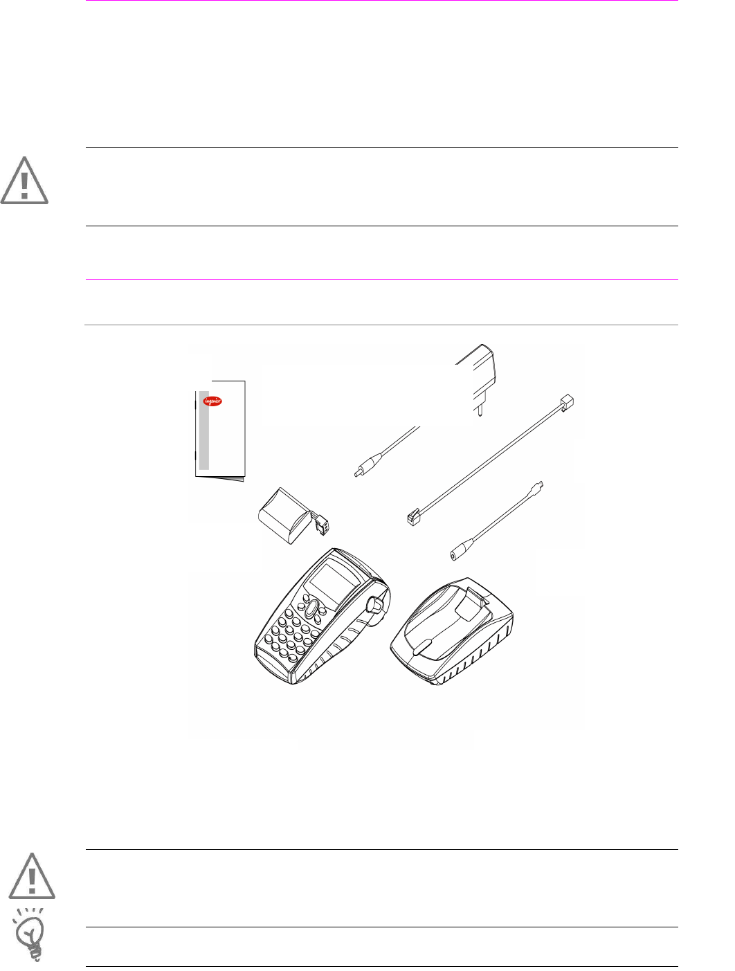
2.1. Content of the box
WARNING
The power supply unit provided with your equipment is specially designed for Ingenico
terminals. Do not use any other power supply. The use of a power supply with apparently
similar voltage/current characteristics may damage your terminal.
ADVICE :
Keep the packaging. It must be re-used whenever the terminal is shipped.
EFT930 terminal unit equipped
with a paper roll
A power supply unit that
connects the power supply to the
electric network
A base receiving the unit
(if no power travel adapter)
A user guide
A battery pack
disconnected
A telephone cable
(With base modem)
Power travel adapter
(When no base)
Or
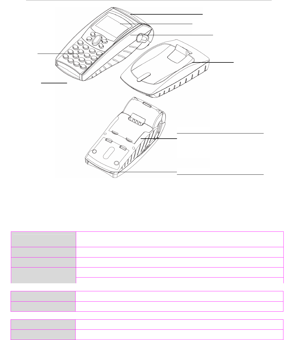
2.2. Overview of the EFT930
Terminal
Base
Weight About 120g
Dimensions 153 x 87 x 33 mm (L x w x h)
Power supply unit
Weight About 100g
2pole sockets 1 A
The power supply unit is specially fitted for INGENICO terminals.
Weight Between 360 g and 410 g, according to the model without paper roll and battery
Dimensions 180 x 79 x 57 mm (L x w x h)
Electrical mains network 100-240VAC / 50-60 Hz - Class II equipment
Mini USB A serial link 100 mA max
Connections on terminal
Mini USB B serial link
1 st Smart
card reader
Base unit
Backlit keyboar
d
Magnetic card
reader
Compartment where are located :
• the battery pack
• the modules SAM1/ SAM2
Large graphic display
Easy loading printer
Compartment where are located :
• the modules SAM3/SAM4 or SIM
• the modules MMC or SDCARD
• the 2
nd
Smart card reader
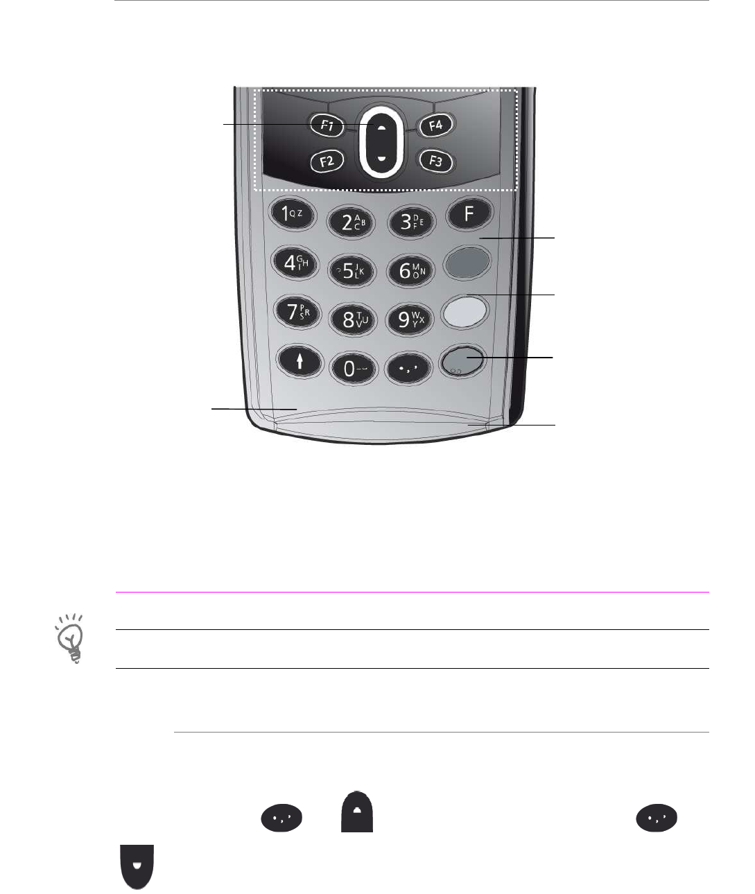
2.3. Keyboard details and functionality
This chapter describes the key functions of a terminal with no specific application. Some
keys can have other functions according to the applications that are in the terminal.
3. Use of the terminal
ADVICE
Before to use the terminal, always check if the roll of paper is present.
3.1. Adjusting contrast
If you wish to increase or to decrease the contrast of the characters displayed on screen,
press simultaneously and in order to decrease the contrast, or and
in order to increase the contrast.
Keep pressing the keys as long as necessary.
The navigation keys
navigate in the terminal menus
The function key accesses the
different application menus
The red key cancels the procedure
in progress
The green key validates input
selections and information
The arrow key advances the paper a
few centimetres
It is also used to switch on the
terminal
The yellow key cancels the last
character
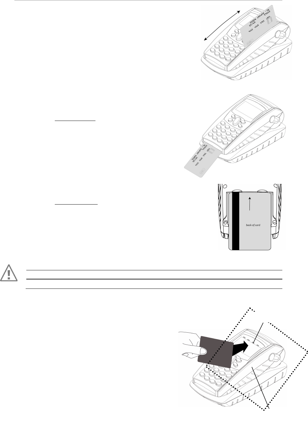
3.2. Reading card
Magnetic stripe card
The card can be read either from bottom to top or from top
to bottom, with the stripe facing the terminal.
Use a regular movement in order to ensure a reliable card
reading.
Smart card
• 1
st
card reader : insert the card horizontally
with the metal chip facing upwards and leave in
position throughout the transaction.
• 2
nd
card reader : is located on back of the terminal.
Insert the card up side down, magnetic stripe visible.
(Optional)
Warning
Switch off the terminal before opening the cover.
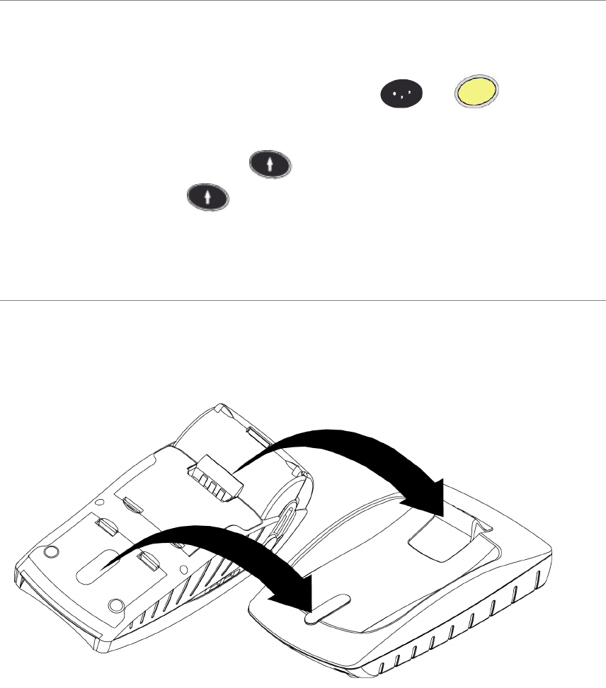
Contactless (if available on your terminal)
• Bring the card firmly up to the active
zone. Keep the card close to the reader during the
transaction
• The 4 green LEDs indicate that the
transaction is completed. (as shown on the
picture)
The terminal behavior for the cardholder may very
depending on:
• The terminal environment
• Local usage (language…)
Active zone
Green leds
3.3. Switching off the terminal
If the battery is empty and the terminal in use is removed from its base, the terminal
automatically shuts off.
It may also be forced stopped by pressing simultaneously and (yellow key)
for one second.
In order to restart the terminal, press on the keyboard. For EFT930 colour and
contactless terminals, press on the keyboard until : -) appears on the screen.
3.4. Installing the terminal on the base
Connecting the terminal on the base
Place the EFT930 between the flanges on its base so that the contacts of the EFT930
engage on the contacts provided on the base (see picture below).
Using the modem base
Once installed, the base modem is designed to always be plugged into the mains network
and be connected to a telephone line. The telephone line should not be shared.
The portable may be placed back on its base after each transaction.
It must be placed on its base in the following cases :
• When telephone network is used for : authorization request, remote collection,
downloading, check processing (If the base is connected to a check reader).
4. Installation
4.1. Recommendations
Location of the terminal
Place the base on flat surface near an electric socket and a telephone socket. The terminal
should be placed far from any very hot zones, protected from vibrations, dust, damp and
electromagnetic radiation (computer screen, anti-theft barrier etc.).
Operating conditions
Ambiant temperature from +5°C to +45°C
Max relative humidity 85% at +40°C
Storage conditions
Ambient temperature from -20°C to +55°C
Max relative humidity 85% at +55°C
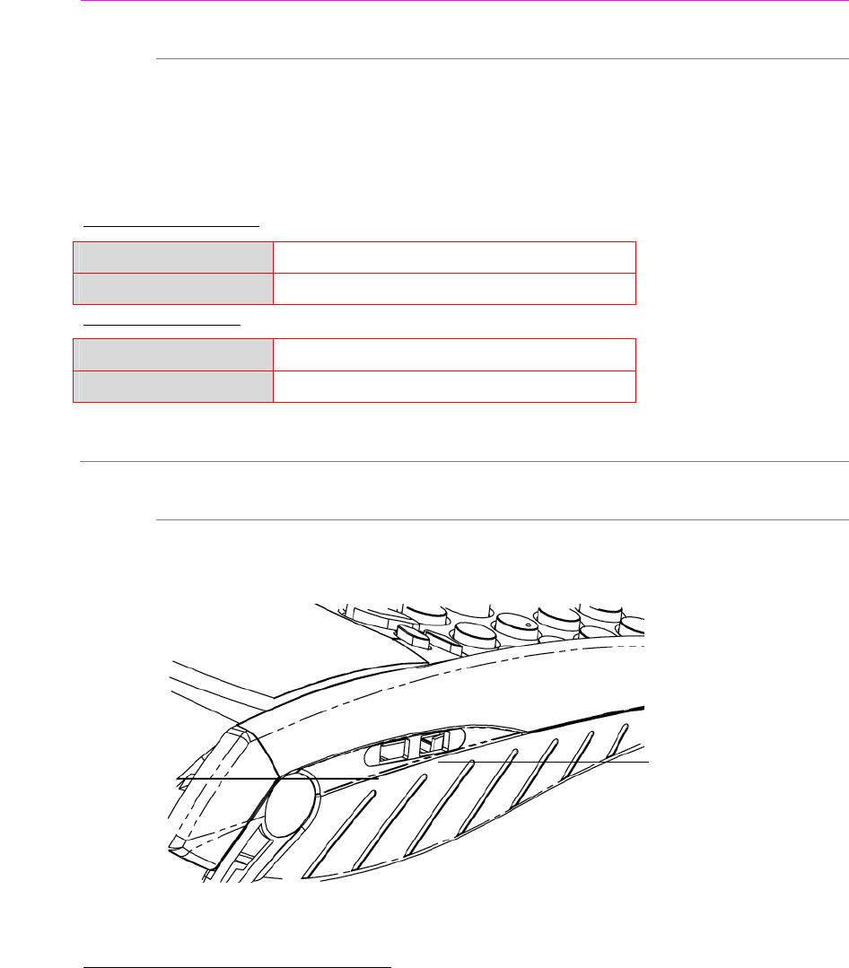
4.2. Terminal connections
• There are 2 USB connectors on the left side of the EFT930 Wireless terminal.
(See below picture)
*Mini USB durability : up to 5000 mating cycles
• The terminal supports USB Keys Class 100 mA with format FAT or FAT32
• The USB Key has to be used with a USB adapter (refers to accessories section)
Mini-USB Host A*
Connector used for USB
Key, etc…) Mini-USB Slave B*
Connector used with
PC, travel charger
adapter, etc...)
4.3. Installing Modules
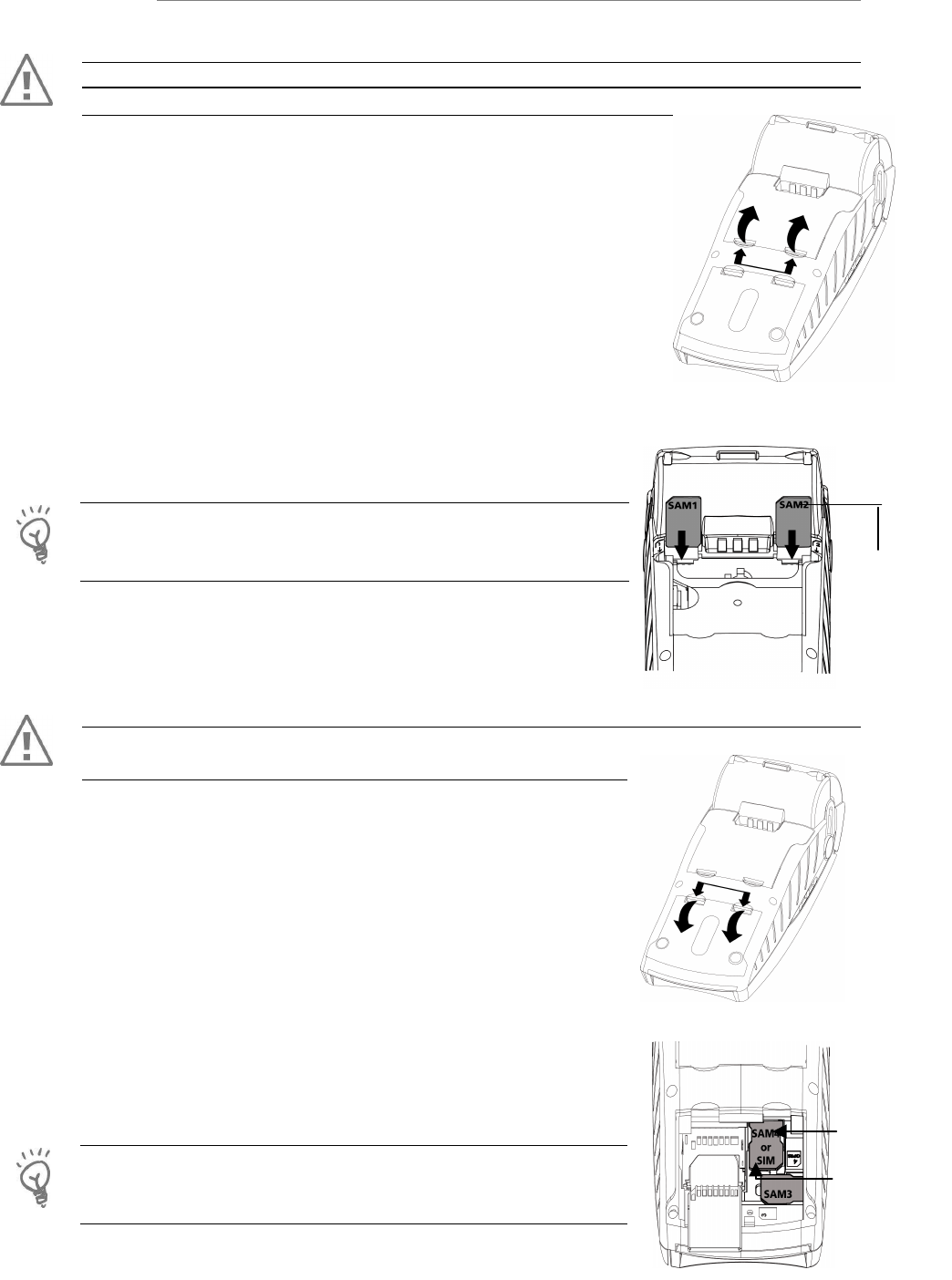
4.3.1.
SAM1/SAM2
WARNING
Switch off the terminal by disconnecting the power supply.
The connector modules security SAM are located inside the terminal,
in a closed compartment.
• Turn the terminal and unclip the top cover flap by pushing
on the clips with your nails as shown with the arrows on the
picture
• SAM1 and SAM2 are indentified by the engraved marks on
the lower housing
• When introducing a SAM in its slot, be sure to put the
cut corner as indicated on the picture
• Close the cover flap
TIP
Use a piece of adhesive tape to grip the SAM for easier and
faster removal.
4.3.2.
SAM3/SAM4 or SIM
WARNING
Switch off the terminal prior to inserting the modules
• Open the lower cover flap, by pushing on the clips with
your nails as shown on the picture
• SAM3 and SAM4 or SIM are indentified by the engraved
marks on the lower housing
• When introducing a SAM in its slot, be sure to put the
cut corner as indicated on the picture
For easier introduction the cut corner is also indicated with an
engraved marks on the lower housing
Close the cover
TIP
Use a piece of adhesive tape to grip the SAM for easier and
faster removal.
Cut corner
position
Cut corner
position
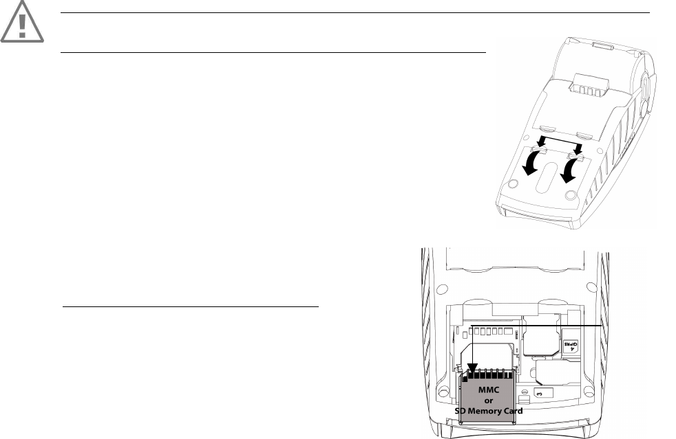
4.3.3.
MMC or SD Memory Card
Open the lower
cover flap to access the MMC or the SD Memory Card area.
CAUTION:
Switch off the terminal before opening the cover.
To install a MMC or a SD Memory Card (SD and SDHC):
• Open the lower cover flap as indicated with the arrows on
the picture
• Insert the MMC or a SD Memory Card into the connector
slot shown by the arrow on the figure.
Be sure to put the cut corner as indicated on the figure
• Close the lower cover flap
The terminal supports SD and SDHC up to 4GB
Cut corner
position
4.4. Paper roll
4.4.1.
Mains characteristics of INGENICO paper roll
Characteristics Precisions
Colour White
Width 58 mm
Diameter 40 mm
Length About 18 metres
• The thermal paper can be deteriorated by poor storage conditions, so we
recommend you to avoid :
– Storage in hot wet places (near air-conditioner, humidity higher than 85%)
– exposure to sunlight or ultraviolet for long periods
– contact with organic solvents (solvent type adhesive)
– direct contact with materials containing plasticizers (PVC transparent
folders or envelopes)
– direct contact with «diazo» papers
– direct contact with water
– Rubbing or pressing the paper too strongly
WARNING
For best product performance, only use heat sensitized paper approved by Ingenico.
Ingenico terminal features an “easy loading” printer, for easy paper roll replacement.
WARNING
Switch off the terminal prior to installing a paper roll.
Use only paper approved by Ingenico (diameter 40 mm).
The use of non approved paper is likely to damage the printer of your terminal.
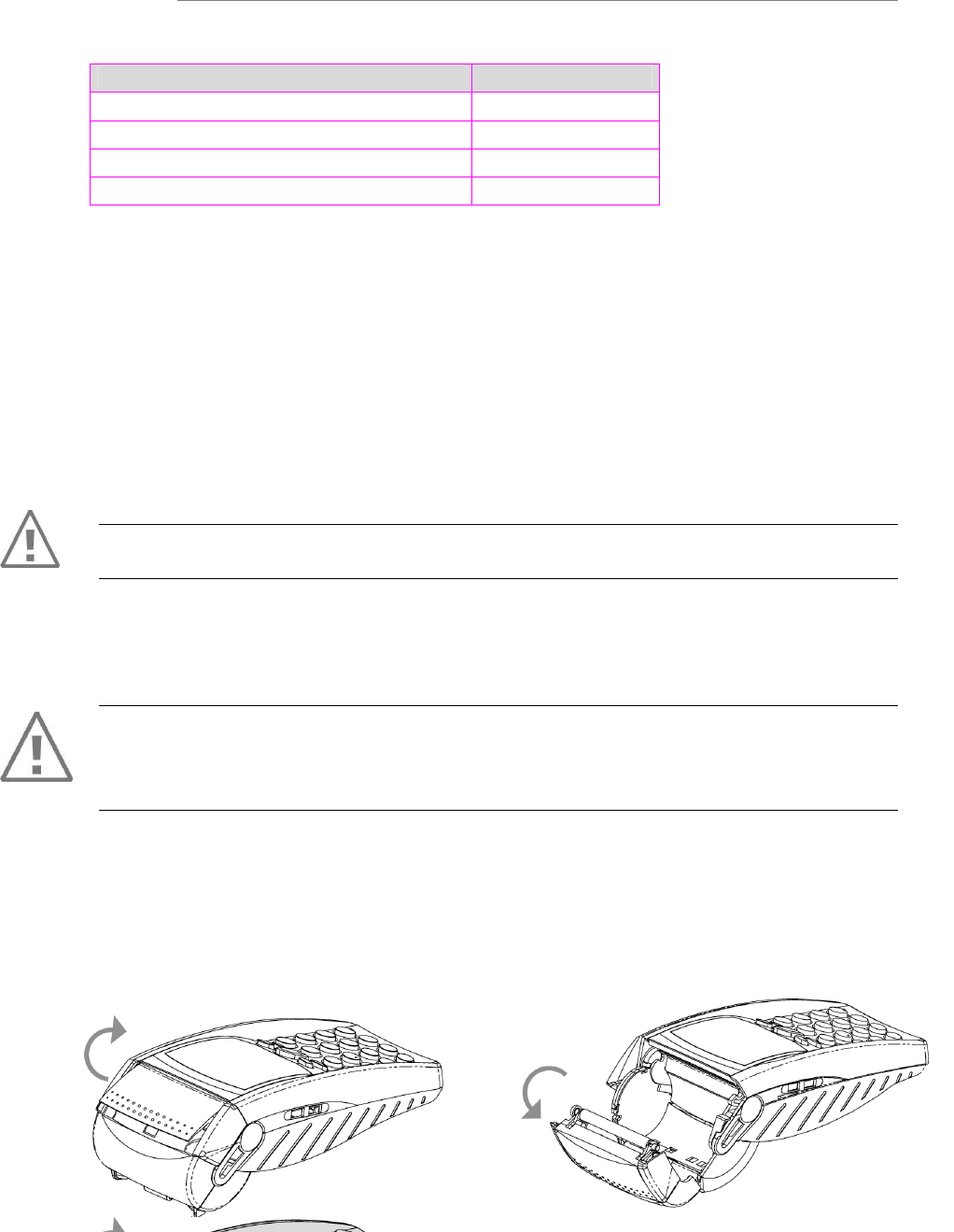
4.4.2.
Installing paper roll
• Open the paper compartment by lifting the catch located at the rear of the EFT930
and pull the cover to the rear of the terminal.
•
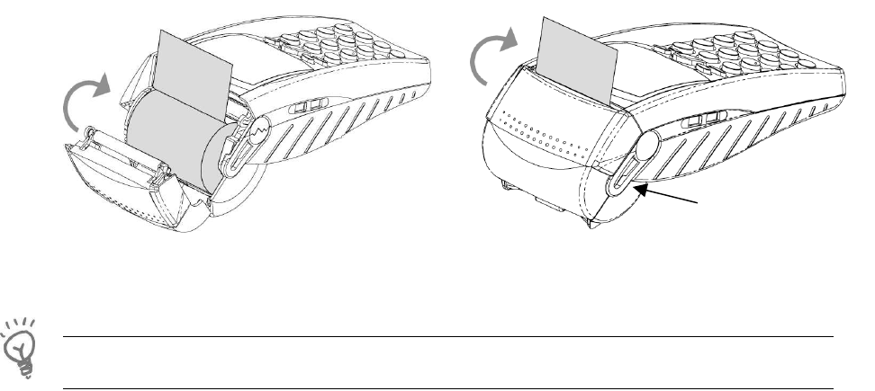
• Insert the paper roll in the compartment following the directions shown on the
below picture
• Pull the paper up to the top of the terminal
• Maintain the paper and close the lid
• Press simultaneously on both upper corners of the paper flap, until it clips into
position
ADVICE
If you insert a new roll, tear off the first length (one complete turn).
Level paper
4.5. Battery
4.5.1.
Main characteristics
Characteristics NimH 1500 mAh Li-ion 1700 mAh
Capacity* Up to 300 transactions typical Up to 340 transactions typical
Charge 50% capacity in 2 h; full
capacity in about 8 hours
50% capacity in 1.5 h; full capacity
in 4 hours
Autonomy Up to 300 h in stand by up to 340 h in stand by
* The battery capacity depends on the model of terminal and its use
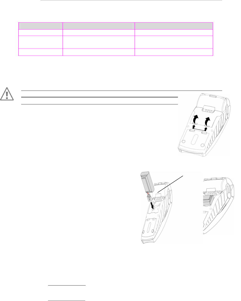
4.5.2.
Installing the battery
WARNING
Switch off the terminal prior to connecting the battery.
• Turn your terminal and unclip the cover flap battery by
pushing on the clips with your nails as shown on the picture
• Disengage the cover
• Take the battery pack included in the box
• Locate the battery pack connector fool proofing
and the board connector located under the battery
compartment
• Plug the battery pack connector on the
board according to the connector locating system and
the red wire (as shown on figure).
Verify that it locks
• Place the battery pack in its compartment
• Close the battery compartment cover flap
4.5.3.
Charging the battery
When does the battery need to be charged?
• On initial start up, charge the battery for 16 hours under the environmental
conditions stated above
• When used daily, the terminal recharges its batteries each time it is placed on
its base . Charging is automatic
• A completely discharged battery requires up to 8 hours for a complete
recharge according to the type of battery
Red wire

Where does the battery need to be charged?
•
••
•
The environment in which the charge takes place influences battery lifetime and
autonomy (number of transactions out of base)
The optimal conditions are as follows:
Charging away from any external heat source (radiator, sun, enclosed area…)
The optimal temperature is between +15°C and +25°C
How does the battery need to be charged?
Using the base
•
••
•
Place the terminal on its base
•
••
•
Check if the electrical plug symbol appears on the terminal screen and if the
battery symbol is flashing (=battery charging).
Using the power travel adapter (the terminal is out of its base)
• Connect the power supply unit to the power travel adapter
• Connect this assembly to the mini-USB slave connector located on the left side of
the terminal
• Connect the power supply unit to the power supply mains network
• Check to see if the battery symbol is flashing (=battery charging)
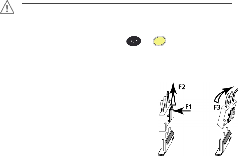
4.5.4.
Changing the battery
It is imperative to use a battery authorized by Ingenico.
There is danger of explosion if battery used is not approved by Ingenico.
• Remove the portable from its base
• Turn it off by pressing simultaneously and (yellow key) for about one
second
• Remove the cover of the battery housing (see section 4.5.1 “installing battery”)
• Lift the battery and remove it from its compartment
• Carefully disconnect battery, following the
instructions below.
a) Unlock the connector by pressing the locking
mechanism as indicated by F1 arrow while pulling
wires (F2 arrow), to disconnect the connector.
Release traction on it as soon as the connector
comes unclipped
b) Finish extracting connector by tilting it slightly
(F3 arrow) to bring it away from the terminal
housing
• Inform the terminal that its battery has been changed. Do so by starting the
terminal without battery and fitting it on its base
• Connect and install the new battery by following the instructions in section 4.5.1
“Installing battery”
• Close the battery cover flap and charge the battery. See section "4.5.3 “Charging
the Battery"
• In order to preserve the environment, dispose of used batteries in compliance with
current recycling legislation in the country
• If the terminal is stored for a long time (more than two months), remove the
battery from the terminal
The terminal memorizes that there is no battery simply by powering up. It will then
correctly perform with the next battery.
5. Base
5.1. Base identification
Base
charger
Base
Modem
1RS232
Base
Modem
2RS232
Base
Ethernet
Base
Ethernet
Modem
Base
BM
1RS232
Base
BM
2RS232
Base
BE
Base
BEM
EFT930P
EFT930G
EFT930B
EFT930W
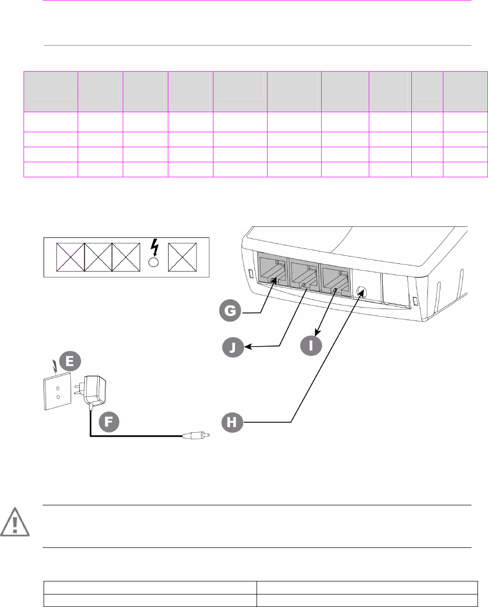
5.1.1. Base charger (EFT930G or EFT930W)
WARNING
Select an electrical socket that complies with the general safety instruction given in section
6 “Recommendations” of this document.
E = Mains network socket F = Power supply unit
H = Power supply input - 2pole sockets 1 A G, J, I = not functional
Follow the below instructions:
• Connect the power supply unit F to the base socket H.
• Connect the power supply unit F to the main network socket E.
Marking
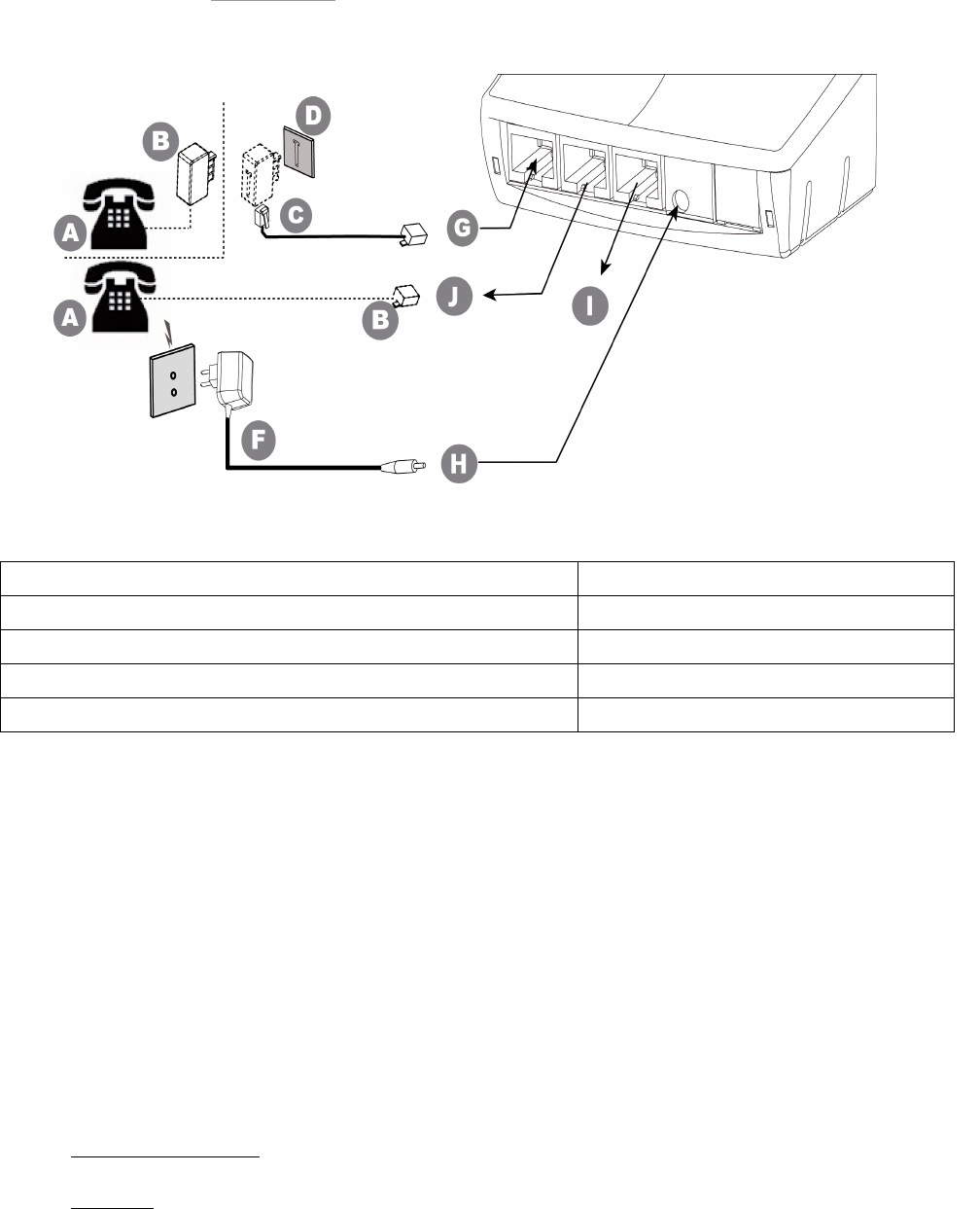
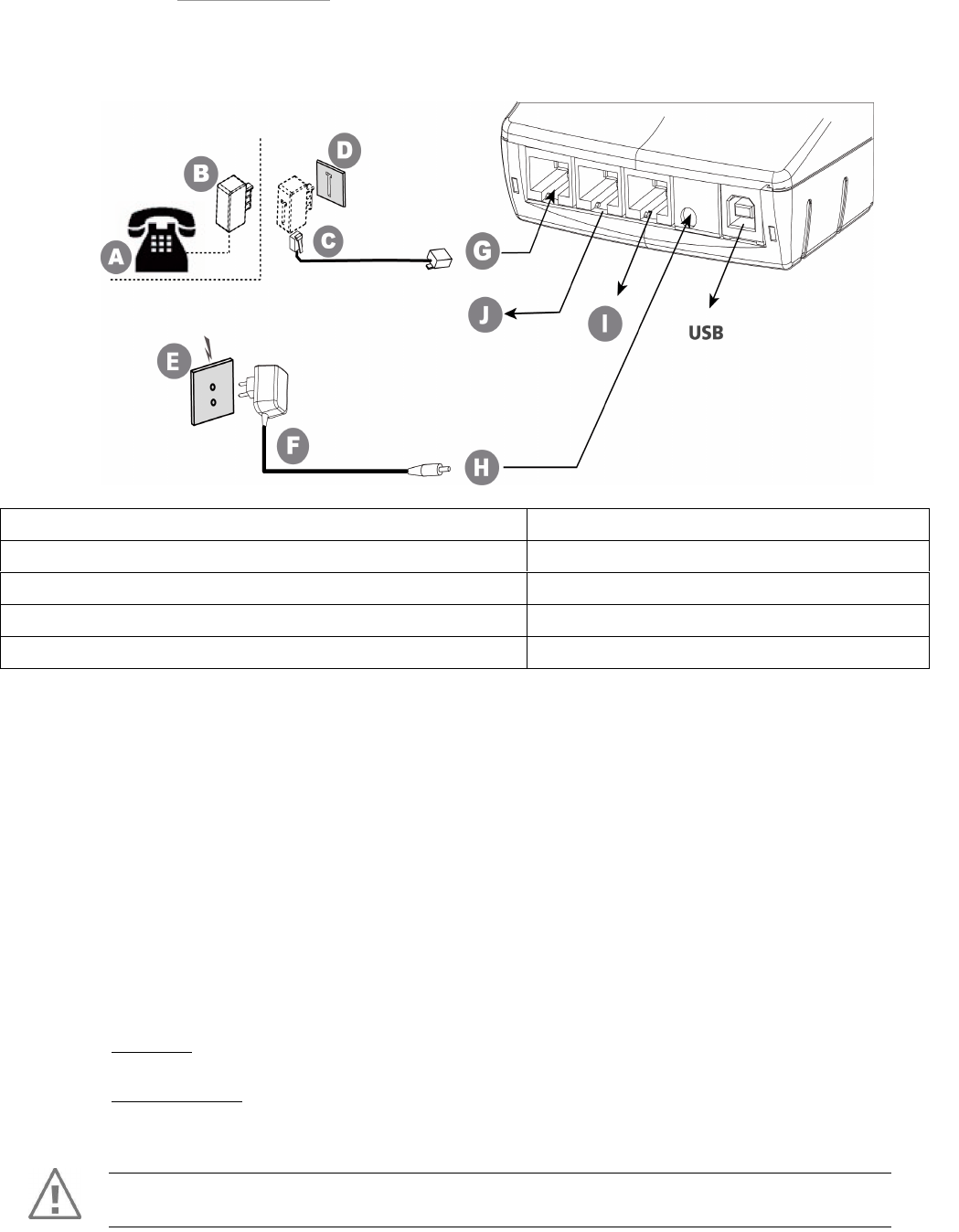
5.1.2. Base Modem
• With 1 RS232 (EFT930P/EFT930G/EFT930W)
Follow the below instructions to connect the base to the telephone network :
• Connect telephone plug C equipped if necessary with user country specific
telephone plug, to the telephone network D.
• Connect the other end of the wire to the base (socket G).
• Connect the mains power supply wire to the base (socket H).
• If necessary, connect the telephone A.
(Telephone A is not required for the terminal to operate).
- France: plug B to the telephone network D through the piggyback plug
- other countries: telephone is connected to the base through the socket J (RJ-
type connector).
• Connect power supply block F to the mains electrical socket E.
Socket G (=socket J) : TNV-3 circuit: Telecommunication Network Voltage, as per safety
standard EN 60950-1.
Socket I : SELV circuit: Since these links are Safety Extra Low Voltage circuits, they must be
interconnected to units which have interfaces powered by the same type of circuits.
Turn off the terminal prior to connecting the base to the appropriate network.
Marking
A = possible telephone handset B =
telephone connector (country specific)
C = connection to the telephone network D = telephone network socket
E = mains power socket F = power adapter
G = telephone network - port RJ11 (telephone cable 3m) H = power input - 2pole sockets 1 A
I = RS232 (cash register, local loading tool, etc.) Level RS 232/V28 J = telephone handset output
• With 2 RS232 (EFT930P/EFT930G/EFT930W)
Follow the below instructions to connect the base to the telephone network:
• Connect telephone plug C, possibly in conjunction with a closing relay satisfying the
standards applicable in the country of use, to the telephone network D.
Connect the other end of the cable to socket G on the base.
• If present, connect telephone A (the presence of telephone A is not required for the
terminal to function)
• France: connect B to the telephone network D via the stackable socket
Connect the power supply unit F to the mains power supply network socket.
Socket G: TNV-3 circuit: Telecommunications Network Voltage, in accordance with safety
standard EN 60950-1.
Sockets I and J: SELV circuit: Since these links are Safety Extra Low Voltage circuits, they
shall be interconnected to equipment with interfaces supplied by circuits of the same type.
WARNING
Switch off the terminal prior to connecting the base to the appropriate network.
Marking
A = possible telephone handset B = telephone connector (country specific)
C = connection to the telephone network D = telephone network socket
E = mains power socket F = power adapter
G = telephone network - port RJ11 (telephone cable 3m) H = power input - 2pole sockets 1 A
I = 1
st
RS232 (cash register, local loading tool...) Level RS 232/V28 J =2
nd
RS232
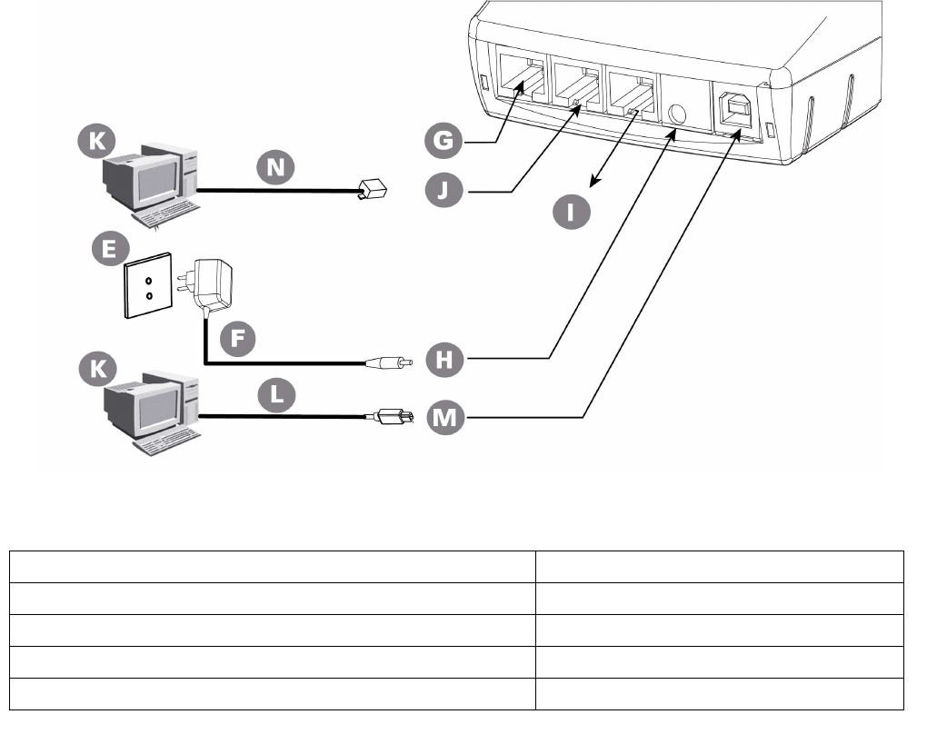
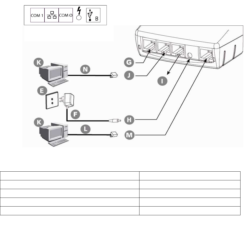
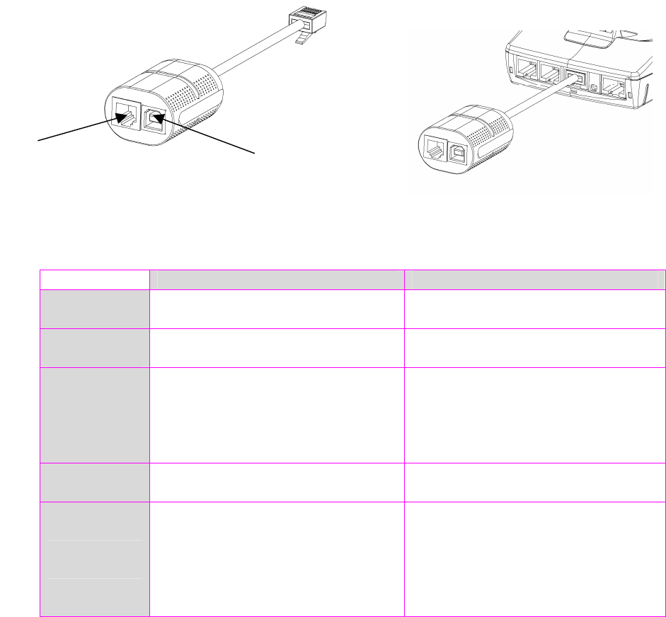
5.1.3. Base Ethernet (EFT930P)
Marking
E = mains power socket F = power supply unit
G = 2
nd
RS232 (4- point connector) H = power supply input - 2pole sockets 1 A
I = 1
st
RS232 (cash register, local loading tool…) Level RS 232/V28 J =Ethernet connection
K = PC L = USB cable
M = USB connection N = Ethernet cable
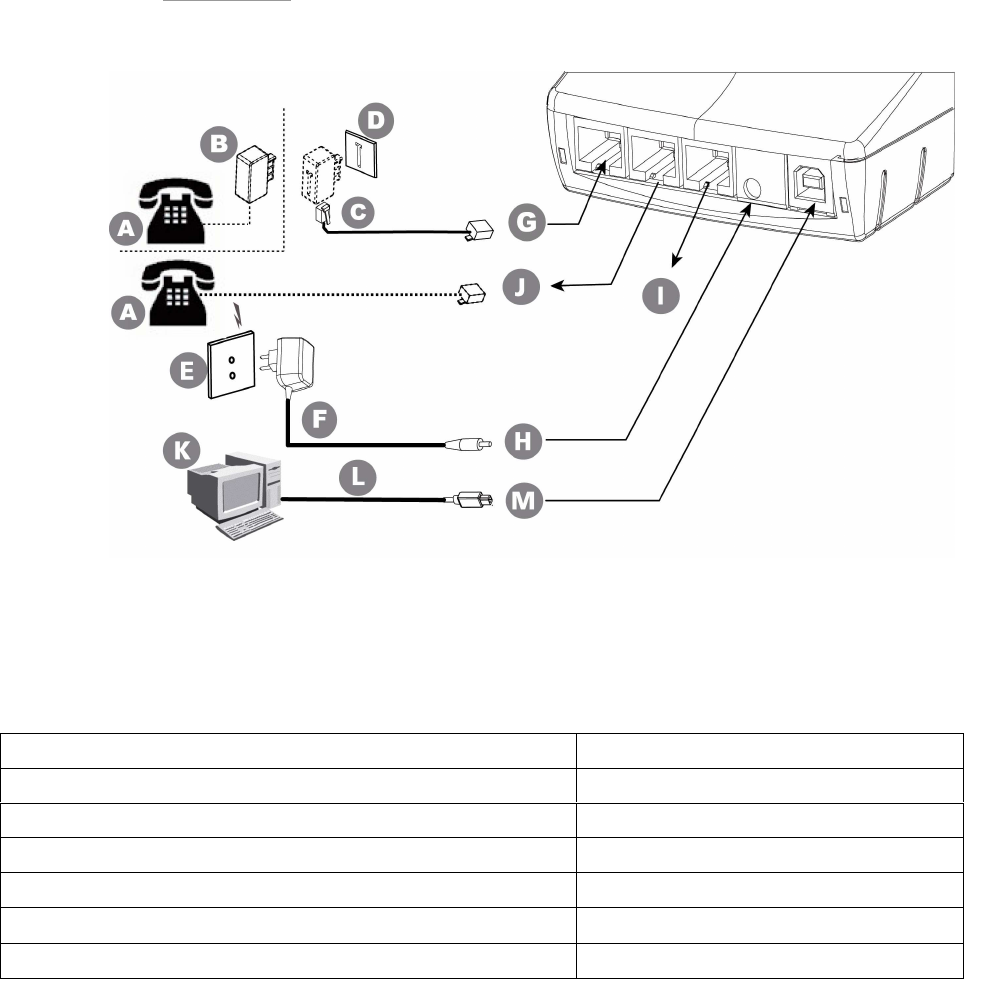
5.1.4. Base Bluetooth Modem
• With 1 RS232 (EFT930B)
Marking
A = possible telephone handset B = telephone connector (country specific)
C = connection to the telephone network D = telephone network socket
E = mains power socket F = power adapter
G = telephone network - port RJ11 (telephone cable 3m) H = power input - 2pole sockets 1 A
I = 1
st
RS232 (cash register, local loading tool…) Level RS 232/V28 J = telephone handset output
K = PC L = USB cable
M = USB link
• With 2 RS232 (EFT930B)
Marking
A = possible telephone handset B = telephone connector (country specific)
C = connection to the telephone network D = telephone network socket
E = mains power socket F = power adapter
G = telephone network - port RJ11 (telephone cable 3m) H = power input - 2pole sockets 1 A
I = 1
st
RS232 (cash register, local loading tool…) Level RS 232/V28
J =2
nd
RS232
K = PC L = USB cable
M = USB link
5.1.5. Base Bluetooth Ethernet (EFT930B)
Marking
E = mains power socket F = power supply unit
G = 2
nd
RS232 (4- point connector) H = power supply input - 2pole sockets 1 A
I = 1
st
RS232 (cash register, local loading tool...) Level RS 232/V28 J =Ethernet connection
K = PC L = USB cable
M = Ethernet connection N = Ethernet cable
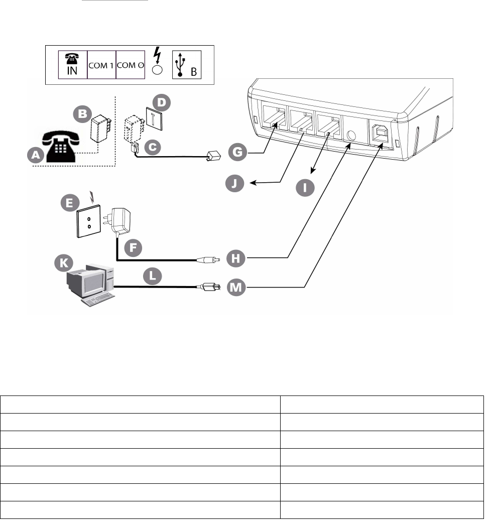
5.1.6. Base Bluetooth Ethernet Modem (EFT930B)
5.1.6.1. Overview
Marking
A = possible telephone handset B = telephone connector (country specific)
C = connection to the telephone network D = telephone network socket
E = mains power socket F = power supply unit
G = telephone network - port RJ11 (telephone cable 3m) H = power supply input - 2pole sockets 1 A
I = 2
nd
RS232 - Level RS 232/V28 and USB connection J = 1
st
RS232 (cash register, local loading tool, etc.)
K = PC L = Ethernet cable
M = Ethernet connection
5.1.6.2. USB/RS232 Cable for Base BEM
This USB/RS232 cable for base BEM is used when a second RS232 and/or a USB connection is
needed.
COM 1 Slave USB
Electronic
interface
Simplified RS232 Slave USB
Number of
wires
CTS RX TX GND 5v-D+ GND
Mechanical
interface
Modular jack 6 points
1=Ground
3=Rx
4=Tx
5=CTS
Type USB socket
1=5V
2=D-
3=D+
4=GND
Logical
interface
300-115 bps
Software – configured framing
12Mbps max
USB 1.1
Connections
examples
Local loading tool
Cash register
Check reader/editor
Computer
External modem
RS 485 converter unit
POS integration
USB Slave
2
nd
RS232
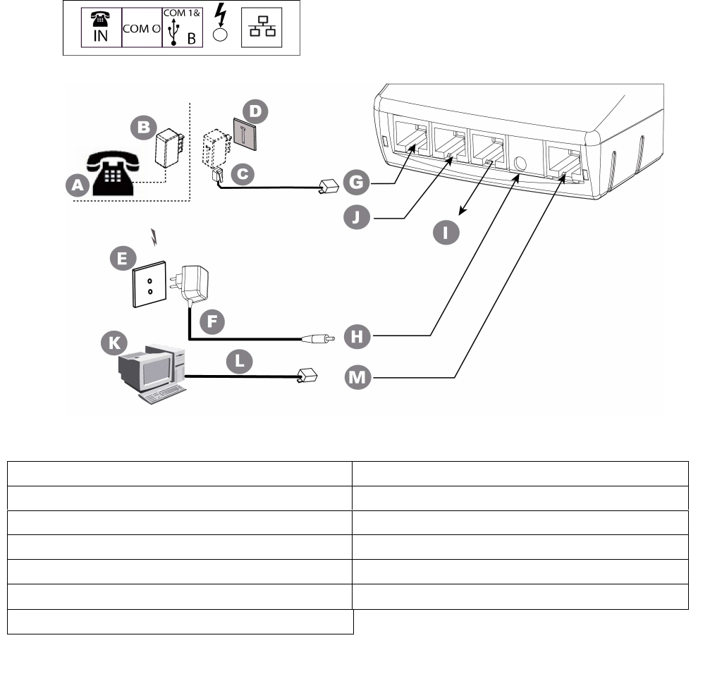
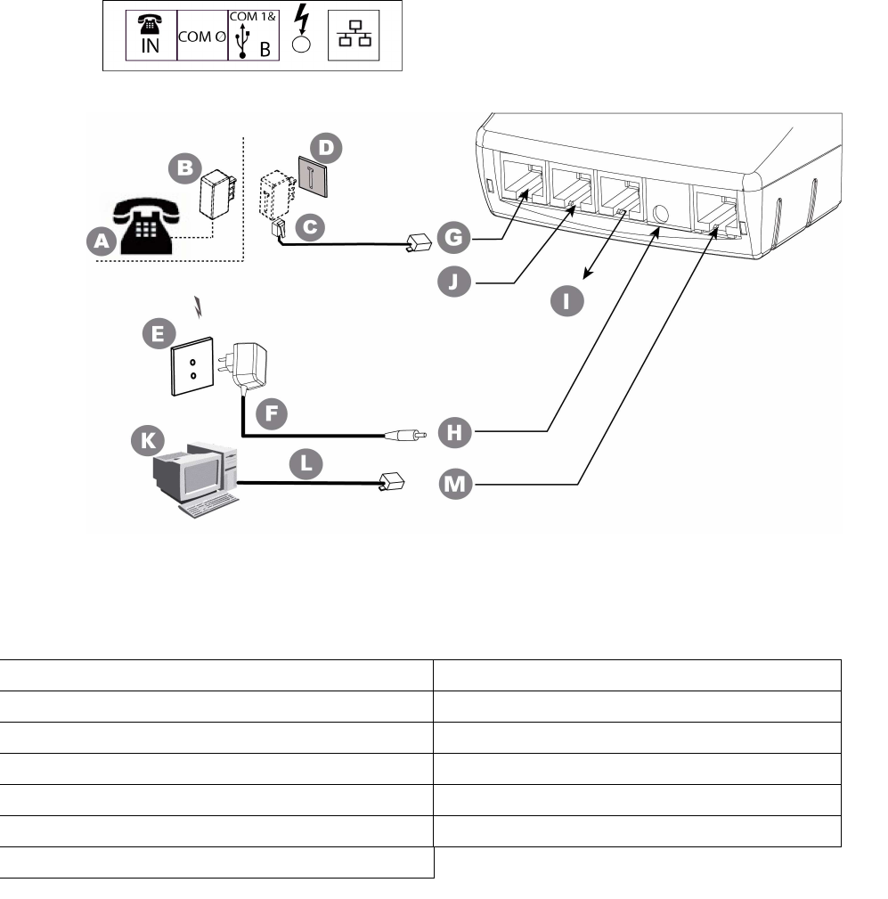
5.1.7. Base Ethernet Modem (EFT930P)
5.1.7.1. Overview
Marking
A = possible telephone handset B = telephone connector (country specific)
C = connection to the telephone network D = telephone network socket
E = mains power socket F = power supply unit
G = telephone network - port RJ11 (telephone cable 3m) H = power supply input - 2pole sockets 1 A
I = 2
nd
RS232 - Level RS 232/V28 and USB connection J = 1
st
RS232 (cash register, local loading tool, etc.)
K = PC L = Ethernet cable
M = Ethernet connection
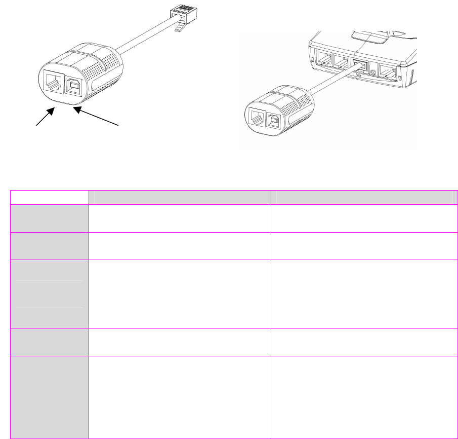
5.1.7.2. USB/RS232 Cable for Base EM
Thes USB/RS232 cable (shown below) is used when a second RS232 and/or a USB
connection is needed on the base EM.
COM 1 Slave USB
Electronic
interface
Simplified RS232 Slave USB
Number of
wires
CTS RX TX GND 5v-D+ GND
Mechanical
interface
Modular jack 6 points
1=Ground
3=Rx
4=Tx
5=CTS
Type USB socket
1=5V
2=D-
3=D+
4=GND
Logical
interface
300-115 bps
Software – configured framing
12Mbps max
USB 1.1
Connections
examples
Local loading tool
Cash register
Check reader/editor
Computer
External modem
RS 485 converter unit
POS integration
USB Slave
2
nd
RS232
6. Recommendations
6.1. Safety
Upon receipt of your terminal you should check for signs of tampering of the equipment. It
is strongly advised that these checks are performed regularly after receipt. You should
check, for example: that the keypad is firmly in place; that there is no evidence of unusual
wires that have been connected to any ports on your terminal or associated equipment, the
chip card reader, or any other part of your terminal. Such checks would provide warning of
any unauthorised modifications to your terminal, and other suspicious behaviour of
individuals that have access to your terminal. Your terminal detects any “tampered state”.
In this state the terminal will repeatedly flash the message” Alert Irruption!” and further
use of the terminal will not be possible. If you observe the “Alert Irruption!” message, you
should contact the terminal helpdesk immediately.
You are strongly advised to ensure that privileged access to your terminal is only granted to
staff that have been independently verified as being trustworthy.
CAUTION : NEVER ask the customer to divulge their PIN Code. Customers should be
advised to ensure that they are not being overlooked when entering their PIN Code.
Powering down the EFT930 base:
Disconnect the EFT930 power supply block adapter the electrical mains network.
Lithium battery
The EFT930 is fitted with a lithium battery which can only be accessed and serviced
by a qualified technician.
The EFT930 is fitted with battery specially designed for this terminal.
• Only use the appropriate chargers and batteries listed in the Ingenico’s catalogue.
• Do not short-circuit the battery.
• Do not attempt to open the battery case as its components cannot be modified.
• Used batteries must be disposed of at the appropriates sites.
Warning
There is a risk of explosion if the battery is incorrectly replaced or is placed in a fire.

Electrical power outlet
The electrical outlet must meet the following criteria:
• Must be installed near the equipment and easily accessible;
• Must meet standards and regulations in the country where used;
• For type A plug, the protection of the installation must be set to 20 A.
Telephone network
The phone jack must comply with standards and regulations in the country where
used.
SAM1 and SAM2 readers compartment
The cover flap for battery, SAM1 and SAM2 readers located underneath the terminal,
must be in place during the normal operation of the terminal. See sections "Removal
of SAM1 and SAM2 modules" as well as "Connecting the battery".
Cover flap for Second Card Reader, SAM3 and SAM4 (or SIM) readers
The cover flap for the Second Card Reader, SAM3 and SAM4 (or SIM), located on the
underside of the terminal must be in place during normal operation. See section
"Removal of SAM3 and SAM4 (or SIM) modules".
On airplanes
Your handset must be switched off by removing the battery pack. Remove the
battery from the terminal when on an airplane.
Non-compliance with these safety rules may result in legal action and/or a ban on
later access to cellular network services.
Explosion areas
Certain regulations restrict the use of radio equipment in chemical plants, fuel depots
and any site where blasting is carried out. You are urged to comply with these
regulations. The terminal shall be protected by a specially fitted and certified cover
enabling use in proximity to a fuel pump.
Electronic health appliances
Your handset is a radio transmitter which may interfere with health appliances, such
as hearing aids, pacemaker, hospital equipment, etc.
Your doctor or the equipment manufacturer will be able to provide you with
appropriate advice.
6.2. Telephone call
You have an urgent call to make while the EFT930 is occupying the line.
In order to get a dial tone:
Place the handset in the hang up position and:
press the red key (=cancel)
or disconnet the power supply from the mains network
or disconnet the EFT930 telephone connector from the telephone call socket, and
place the telephone connector into the telephone wall socket.
You hear a dial tone within 6 seconds.

7. Standards
CE Marking
The CE marking indicates that product EFT930P/G/B/W complies with the requirements of
European Directive 1999/5/EC of 9 March 1999 on Radio and Telecommunications Terminal
Equipment for:
• The protection of the health and the safety of the user and any other
person.
• The protection requirements with respect to electromagnetic compatibility.
and complies with the following harmonised standards:
EFT930P
EN 60950-1 /2001 According to 73/23/EEC (Low Voltage Directive)
EN 55022 A2 /2003 According to 89/336/EEC (EMC Directive)
EN 55024 A2 /2003 According to 89/336/EEC (EMC Directive)
EFT930G
EN 60950-1 /12-2001 According to 73/23/EEC (Low Voltage Directive)
EN 301489-1-7 /08-2000 According to 89/336/EEC (EMC Directive)
EN 301 511 /12-2000 According to 1999/5/EC (R&TTE Directive)
EN 50360 /07-2001 According to 1999/519/EEC (R&TTE Directive)
EFT930B
EN 60950-1 /12-2001 According to 73/23/EEC (Low Voltage Directive)
EN 301489-1-17 /08-2000 According to 89/336/EEC (EMC Directive)
EN 300 328 v1.4.2 /12-2000 According to 1999/5/EC (R&TTE Directive)
EFT930W
EN 60950-1 /12-2001 According to 73/23/EEC (Low Voltage Directive)
EN 301489-1-17 /08-2000 According to 89/336/EEC (EMC Directive)
EN 300 328 v1.4.2 /12-2000 According to 1999/5/EC (R&TTE Directive)
EFT930 with CLESS
EN 301489-3 /08-2000 According to 89/336/EEC (EMC Directive)
EN 300 330-2 /06-2001 According to 1999/5/EC (R&TTE Directive)
EN 50357;EN50364 /2001 According to 1999/519/EEC (R&TTE Directive)
And, for the whole range, complies with the European approval specification on
connecting terminals with DTMF dialling to the public switched telephone network
(Council Decision 1998/482/EC, Council Decision 1999/303/EC):
TS 103021-1/2/3 /09-2003
TR 103000-1/2/3/4 /06-2003
ES 201187 /03-1999
FCC/IC Compliance (EFT930G /B)
The FCC ID for EFT930G model is: XKB-EFT930G and IC number is: 2586D-EFT930G
The FCC ID for EFT930B model is: XKB-EFT930B (terminal); XKB-BAS930B (base) and IC
number is: 2586D-EFT930B (terminal); 2586D-BAS930B (base)
Warning
This compliance is valid with the use of a ferrite (
74271112)
around the alimentation cable
(2 turns) from the base, and with the use of an ethernet shielded cable (if applicable)
• This device complies with Part 15 of the FCC Rules and with RSS-210 of Industry
Canada.
Operation is subject to the following two conditions:
(1) this device may not cause harmful interference, and
(2) this device must accept any interference received, including interference that may
cause undesired operation.
• This class (B) digital apparatus complies with Canadian ICES-003.
• Warning: Changes or modifications made to this equipment not expressly approved
by INGENICO may void the FCC authorization to operate this equipment.
• This equipment has been tested and found to comply with the limits for a Class B
digital device, pursuant to Part 15 of the FCC Rules. These limits are designed to
provide reasonable protection against harmful interference in a residential
installation. This equipment generates, uses and can radiate radio frequency
energy and, if not installed and used in accordance with the instructions, may cause
harmful interference to radio communications. However, there is no guarantee
that interference will not occur in a particular installation. If this equipment does
cause harmful interference to radio or television reception, which can be
determined by turning the equipment off and on, the user is encouraged to try to
correct the interference by one or more of the following measures:
Reorient or relocate the receiving antenna.
Increase the separation between the equipment and receiver.
Connect the equipment into an outlet on a circuit different from that to which the
receiver is connected.
Consult the dealer or an experienced radio/TV technician for help.
• The terminal EFT930B and the base BAS930B operate as a system. These devices
comply with FCC and Industry Canada RF radiation exposure limits set forth for
general population. They must not be collocated or operated in conjunction with
any other antennas or transmitters
• FCC Radiation Exposure (EFT930G)
The antenna is located in the paper compartment at the top of the terminal. For satisfying
RF exposure compliance this equipment should be installed and operated with minimum
distance of 20cm between the antenna and your body.
This transmitter must not be co-located or operating in conjunction with any other antenna
or transmitter.
• Part 68 of FCC Rules (for Modem version Only)
This equipment complies with Part 68 of the FCC rules and the requirements adopted by
the ACTA. On the bottom of this equipment is a label that contains, among other
information, a product identifier in the format US:AAAEQ##TXXXX. If requested, this
number must be provided to the telephone company.
This equipment uses the following USOC jacks: (RJ11C).
A plug and jack used to connect this equipment to the premises wiring and telephone
network must comply with the applicable FCC Part 68 rules and requirements adopted by
the ACTA. A compliant telephone cord and modular plug is provided with this product. It is
designed to be connected to a compatible modular jack that is also compliant. See
installation instructions for details.
The REN is used to determine the number of devices that may be connected to a telephone
line. Excessive RENs on a telephone line may result in the devices not ringing in response to
an incoming call. In most but not all areas, the sum of RENs should not exceed five (5.0). To
be certain of the number of devices that may be connected to a line, as determined by the
total RENs, contact the local telephone company.
If this equipment causes harm to the telephone network, the telephone company will notify
you in advance that temporary discontinuance of service may be required. If advance notice
is not practical, the telephone company will notify the customer as soon as possible. Also,
you will be advised of your right to file a complaint with the FCC if you believe it is
necessary.
The telephone company may make changes in its facilities, equipment, operations, or
procedures that could affect the operation of this equipment. If this happens, the
telephone company will provide advance notice in order for you to make the necessary
modifications to maintain uninterrupted service.
If trouble is experienced with this equipment, please contact Ingenico, or your local
INGENICO distributor or service center in the U.S.A. for repair and/or warrant information. If
the trouble is causing harm to the telephone network, the telephone company may request
you to remove this equipment from the network until the problem is resolved. No repairs
can be done by a customer on this equipment.
Connection to party line service is subject to state tariffs. Contact the state public utility
commission, public service commission or corporation commission for information.
If your home has specially wired alarm equipment connected to the telephone line, ensure
the installation of this equipment does not disable your alarm equipment. If you have
questions about what will disable alarm equipment, consult your telephone company or a
qualified installer.
CAUTION: The user is cautioned that any changes or modification not approved by
INGENICO could void user’s authority to operate the equipment.
End of life
The product belongs to the family of electrical and electronic equipment. Therefore, it is
subjected to the WEEE directive which requires the collection and the recycling at the end
of life product.
The Ingenico products present the symbol for the marking of electrical and electronic
equipment as required by the WEEE Directive.
The crossed-out wheeled bin printed on the product gives the information about
the requirement not to dispose of WEEE as unsorted municipal waste and to
collect such WEEE separately.
To assure that the product is collected and recycled with respect to the environment, you
must contact your supplier (in defect, contact the Ingenico local office or the commercial
head office in charge of your country on
www.ingenico.com
, « contact us » page).
The abandonment or uncontrolled disposal of waste can cause harm to environment and to
human health. So, by recycling your product in a responsible manner, you contribute to the
preservation of natural resources and to the protection of human health.
BATTERIES
If your product contains batteries, they must be disposed of at the appropriate collection
points.
ATEX
(EFT930B/EFT930W)
The EFT930 terminal complies with the health and safety requirements for equipment
intended for use in potentially explosive atmospheres (ATEX) defined in the standard:
EN 60079-15 /2003
The ATEX marking on the EFT930 terminal is:
II 3 G
EEx nA IIA T5
LCIE 06 ATEX6096 X
The specific conditions for safe use are:
• Temperature use range: +5°C to +45°C.
• The equipment shall not suffer impacts greater than 4J.
• Connection via USB cable to computer equipment shall not be performed in the
presence of explosive atmospheres.
• The base shall not be used in the presence of explosive atmospheres.
• When using the terminal in explosive atmospheres, ATEX holster shall be used.

8. Troubleshooting
The terminal does not turn on or does not connect to the telephone line
• Check the power supply and telephone line cables
• Check for electrical power network
The terminal fails to establish a telephone connection
• Check that the tone of the phone line is free
• Check the configuration of the phone line and number to call
• Get technical support
Cards are not read
• Check that the magnetic card is swiped correctly (with magnetic band
to directed the terminal) .
• Swipe again the card with the magnetic stripe movement constant and rapid
• Verify that the magnetic strip is not damaged, grooved or cracked
• Make sure you have inserted correctly the smart card into the smart card reader
and removed the card only after the transaction is performed.
The ticket is not printed
• Check the presence and proper positioning of the paper roll.
Possibly adjust the paper roll following the instructions in this manual (section 4.4
“Installing the paper roll”)
• Check the type of paper used (thermal paper must be used)

“This Document is Copyright © 2009 by INGENICO Group. INGENICO retains full copyright ownership,
rights and protection in all material c
ontained in this document. The recipient can receive this document
on the condition that he will keep the document confidential and will not use its contents in any form or
by any means, except as agreed beforehand, without the prior written permission of
INGENICO.
Moreover, nobody is authorized to place this document at the disposal of any third party without the
prior written permission of INGENICO. If such permission is granted, it will be subject to the condition
that the recipient ensures that any othe
r recipient of this document, or information contained therein, is
held responsible to INGENICO for the confidentiality of that information.
Care has been taken to ensure that the content of this document is as accurate as possible.
INGENICO
however decl
ines any responsibility for inaccurate, incomplete or outdated information. The contents of
this document may change from time to time without prior notice, and do not create, specify, modify or
replace any new or prior contractual obligations agreed upon in writing between
INGENICO and the
user.
INGENICO is not responsible for any use of this device, which would be non consistent with the present
document.
All trademarks used in this document remain the property of their rightful owners.”
Ingenico
192 avenue Charles de Gaulle
92200 Neuilly sur Seine - France
Tél: + 33 1 46 25 82 00 - Fax: + 33 1 47 72 56 95
www.ingenico.com
Your contact
*2
95
00
63