Ingenico CPEM-E1K6567 CONTACTLESS PAYMENT EXPANSION MODULE User Manual USERS MANUAL
Ingenico CONTACTLESS PAYMENT EXPANSION MODULE USERS MANUAL
Ingenico >
USERS MANUAL
Contactless Payment Expansion
Module for the eN-Touch 1000
Installation Guide

Contactless Payment Expansion Module eN –Touch 1000 Installation Guide
Contactless Payment Expansion Module for the eN –Touch 1000
Installation Guide
Part Number DIV350403, Revision A
Released July 2005
Copyright 2005, Ingenico Corp. All rights reserved.
No part of this publication may be copied, distributed, stored in a retrieval system,
translated into any human or computer language, transmitted, in any form or by any
means, without the prior written consent of Ingenico. Ingenico and Ingenico logo are
registered trademarks of Ingenico Corp. All other brand names and trademarks
appearing in this guide are the property of their respective holders. Information in
this document is subject to change without notice.
Noncontractual document. INGENICO owns exclusive rights to this document.
All distributions, copies, entire or partial production, by any process, made without
the authorization of INGENICO will be considered illicit, and will form an
infringement, penalized by the L.335-2 clause and following clauses of the Code of
Intellectual Property.
INGENICO reserves the right to modify the characteristics and the functions of this
device without notice.
INGENICO is not responsible for any use of this device which would be inconsistent
with this document.
Ingenico Inc.
1003 Mansell Road
Atlanta, GA 30076
Tel: 770.594.6000
Fax: 770.594.6003
www.ingenico-us.com
U.S. Help Desk: TotalCARE
Tel: 800.435.3014
Fax: 770.594.6026
Ingenico Canada Ltd.
79 Torbarrie Road, Toronto, Ontario
Canada M3L 1G5
Tel: 416.245.6700
Fax: 416.245.6701
www.ingenico-ca.com
Canadian Help Desk: TotalCARE.
Tel: 888.900.8221
Fax: 905.795.9343
Contactless Payment Expansion Module eN –Touch 1000
Installation Guide 1
Table of Contents
1
Overview ..............................................1
2
Installation Components .......................1
3
Installation Procedure ..........................2
3.1 Preparing the Terminal for the Installation................................ 2
3.2 Expansion Module Installation Steps......................................... 3
4
Testing the Installation.........................6
5
Product Certification............................7
1 Overview
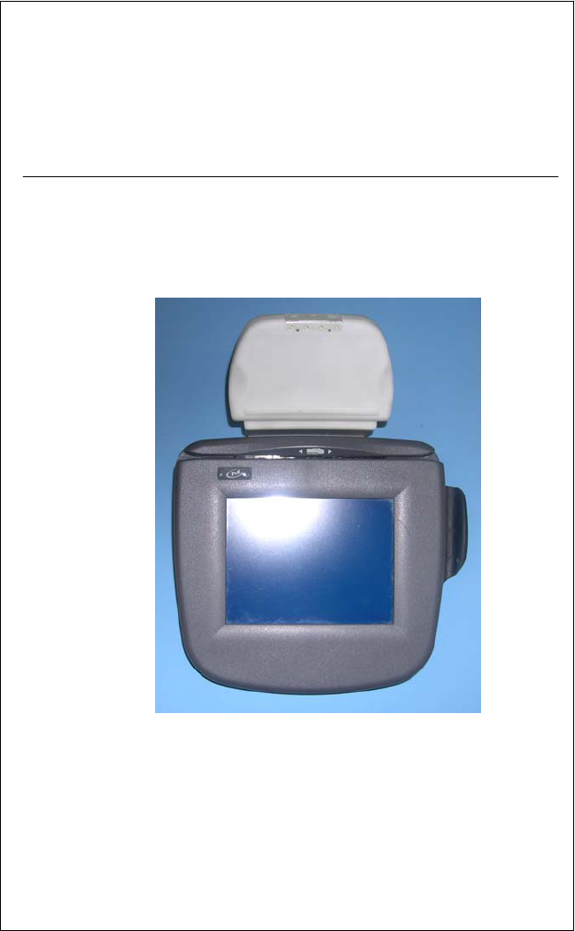
This document describes how to install the Contactless Payment
Expansion Module on the eN-Touch 1000 terminal.
The Expansion Module is based on RFID technology and enables the
terminal to read contact-less smartcards.
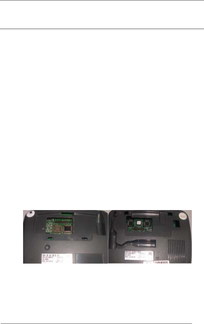
The eN -Touch 1000 is available in 2 models, Tyco/Loki and Thor that
have different plastic feet. See Figure 1.
Figure 1: Terminal Foot area for Thor and Tyco/Loki models
This installation guide applies to both models.
2 Installation Components
The Expansion Module package contains all the components required
for upgrading either of the two eN -Touch 1000 models. The kit
T
y
co/Loki Thor
2 Contactless Payment Expansion Module eN –Touch 1000 Installation Guide
includes the following: Card Reader Unit, Cable, Tyco/Loki Foot, Thor
Foot, Wedge, Double sided tape and Plastic bag with one mounting
screw and two self-adhesive rubber bumps
Only the Expansion Module Foot for your terminal model is
required!
3 Installation Procedure
!
- Only upgrade terminals that are in working order.
- This procedure requires a Philips screw driver.
3.1 Preparing the Terminal for the Installation
1. Disconnect the terminal from power.
2. Place the terminal on a flat surface with the bottom side facing up.
3. Remove the existing Foot from the terminal. Note different procedure
for the two models:
• Thor model only: Using a screwdriver remove the two
mounting screws and detach the Foot. Retain the screws for
the Expansion Module installation.
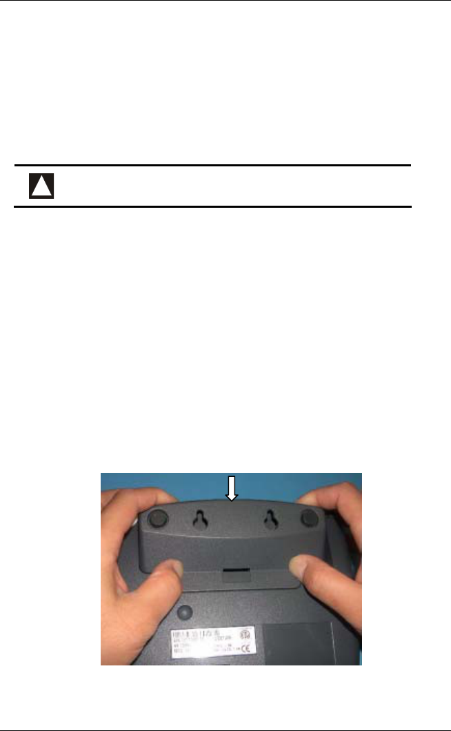
• Tyco/Loki model only: Pinch the middle of the Foot to
release the locking clip and then remove the Foot. See Figure
2.
Figure 2: Removing the existing Tyco/Loki Foot
4. Disconnect any installed cables from the terminal.
Contactless Payment Expansion Module eN –Touch 1000
Installation Guide 3
3.2 Expansion Module Installation Steps
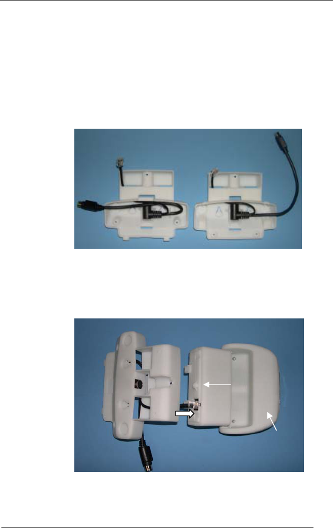
Step 1: Assemble the cable assembly into the Foot required for your
installation as shown in Figure 3. Ensure that the cable is positioned in
the cable retention feature of the Foot. Note that the cable is routed
differently according to the model you have: for the Tyco/Loki model
place the Minidin 9 cable under the RJ cable.
Figure 3: Cable/Foot assembly
Step 2: Insert the RJ connector from the assembled Cable/Foot into the
Reader Unit jack, as shown in Figure 4.
Figure 4: Connect RJ cable to the Reader Unit
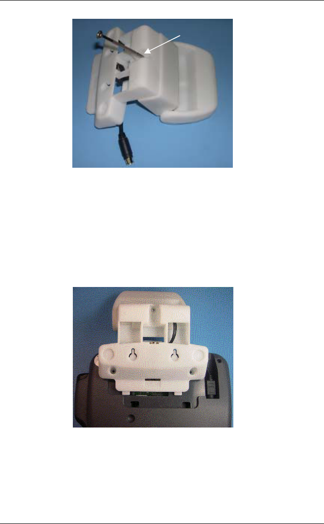
Step 3: Attach the Reader Unit to the Foot by using the two foot
mounting tabs and the mounting screw. See Figure 5
Tyco/Loki Thor
Reader Unit
RJ
Minidin 9
RJ
Minidin 9
Screw hole
Antenna
4 Contactless Payment Expansion Module eN –Touch 1000 Installation Guide
Figure 5: Foot/Reader Unit assembly
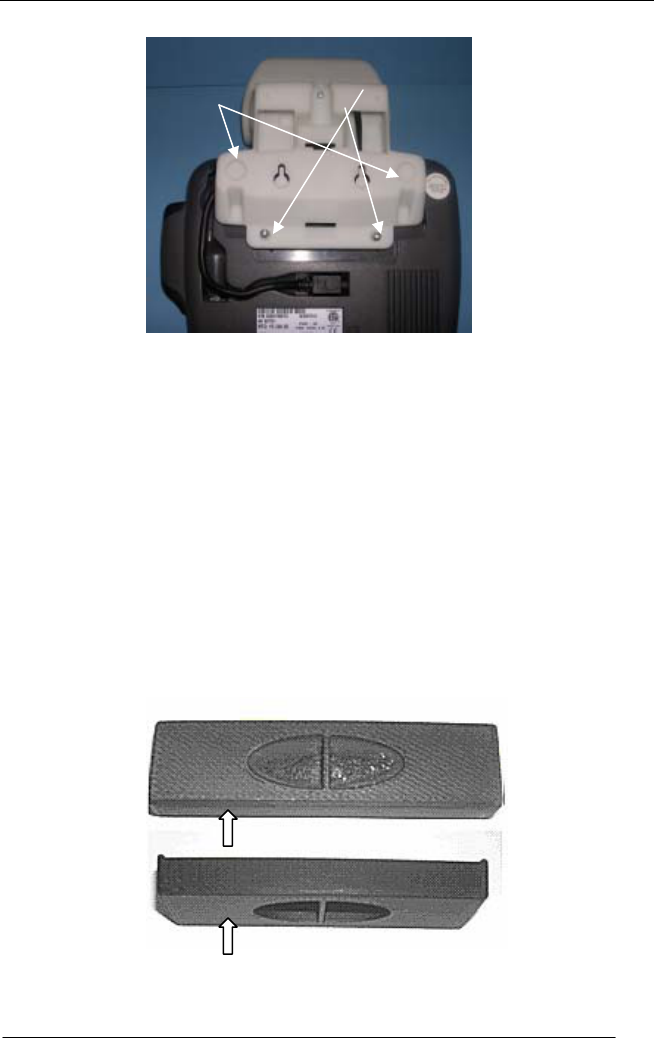
Step 4A-Tyco/Loki model only: Attach the Foot/Reader Unit
assembly to the terminal by connecting first the Minidin 9 connector to
the terminal jack, than placing the two bottom mounting tabs of the
Foot into the terminal recesses and finally by squeezing in the top
mounting tab of the Foot into matching locating hole of the terminal.
Foot mounting screws are NOT required. See Figure 6.
Figure 6: Attach Tyco/Loki Expansion Module to the terminal
Step 4B-Thor model only: Same procedure as for Tyco/Loki model
except the different position of the Foot mounting tabs, Foot mounting
screws and of the Minidin 9 terminal jack. Foot mounting screws
need to be applied. Use the screws removed from the terminal Foot.
See Figure 7.
Mounting
screw
Contactless Payment Expansion Module eN –Touch 1000
Installation Guide 5
Figure 7: Attach the Thor Expansion Module to the terminal
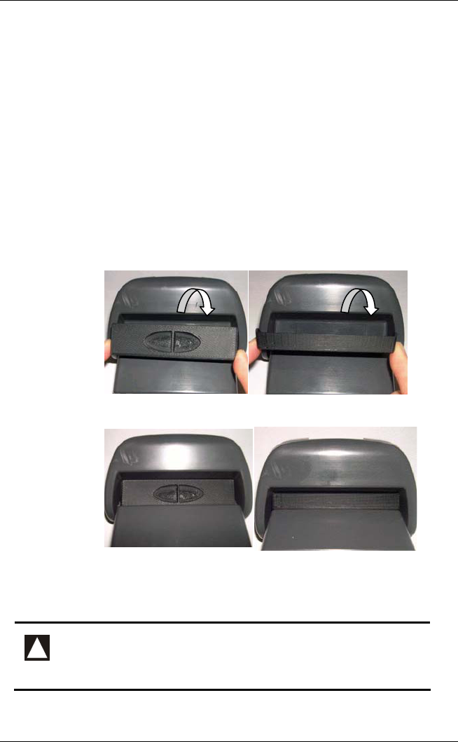
Step 5: Apply the two self-adhesive rubber bumps to the Module Foot
as shown in Figure 7.
The orientation angle of the Card Reader antenna can be adjusted
through 3 discrete positions.
The optional Antenna Positioning Wedge included in the kit can be
used to fix the antenna semi-permanently in Position 1 or Position 2.
Position 3 does not require the wedge.
If the installation of the Antenna Positioning Wedge is required follow
Step 6 and Step 7.
Step 6: Place the double sided tape for the required wedge position as
indicated in Figure 8.
Figure 12: Application of double sided tape
Self-adhesive
bumps here Screws here
Wedge position 1
Wedge position 2
Double sided ta
p
e here
Double sided ta
p
e here
6 Contactless Payment Expansion Module eN –Touch 1000 Installation Guide
Step 7: Install the Wedge as follows:
• Fully insert the Wedge for the desired position in the recess at the
back of the Antenna as shown in Figure 9.
• Ensure the Wedge is located and attached properly to the top of the
Reader surface through the use of the included double sided tape.
• Check the Wedge is locked in the Antenna recess by pushing the
Antenna against the Wedge as shown by the arrows. If
movement, reposition.
Figure 9. Figure 10 shows the results of the Wedge installation.
Figure 9: Wedge installation
Figure 10: Wedge installed
4 Testing the Installation
!
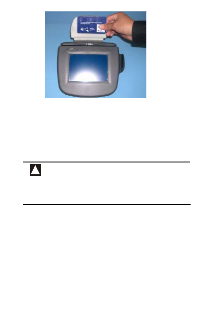
1- Ensure that an application to test contact-less
smartcards is loaded in the terminal.
2- A compatible contact-less smartcard is required.
wedge position 1 wedge position 2
a
n
te
nn
a
a
n
te
nn
a
Contactless Payment Expansion Module eN –Touch 1000
Installation Guide 7
Figure 17: Reading a contact-less smartcard
• Place the contact-less smartcard near the Card Reader.
• Confirm the successful reading of the contact-less smartcard.
5 Product Certification
!
This device complies with Part 15 of FCC Rules. Operation is
subject to the following two conditions:
(1) this device may not cause harmful interference
(2) this device must accept any interference received, including
interference that may cause undesired operation
This equipment has been tested and found to comply with the limits for a Class B digital
devices, pursuant to Part 15 of the FCC Rules. These limits are designed to provide
reasonable protection against harmful interference in a residential installation. This
equipment generates, uses, and can radiate radio frequency energy and, if not installed
and used in accordance with the instruction manual, may cause harmful interference to
radio communications. However, there is no guarantee that interference will not occur in
a particular installation. If this equipment does cause harmful interference to radio or
television reception, which can be determined by turning the equipment off and on, the
user is encouraged to try to correct the interference by one of the following measures:
• Reorient the receiving antenna
• Increase the separation between the equipment and receiver
• Connect the equipment into an outlet on a circuit different from that to which the
receiver is connected
• Consult Ingenico Support for help

8 Contactless Payment Expansion Module eN –Touch 1000 Installation Guide
!
Changes or modifications not expressly approved by manufacturer
could void the user’s authority to operate the equipment