Ingenico L8000CL Contactless RFID payment terminal User Manual
INGENICO Contactless RFID payment terminal
Ingenico >
User Manual.pdf
www.ingenico.com
28-32, boulevard de Grenelle, 75015 Paris - France / (T) +33 (0)1 58 01 80 00 / (F) +33 (0)1 58 01 91 35
Ingenico - SA au capital de 47 656 332 / 317 218 758 RCS Nanterre
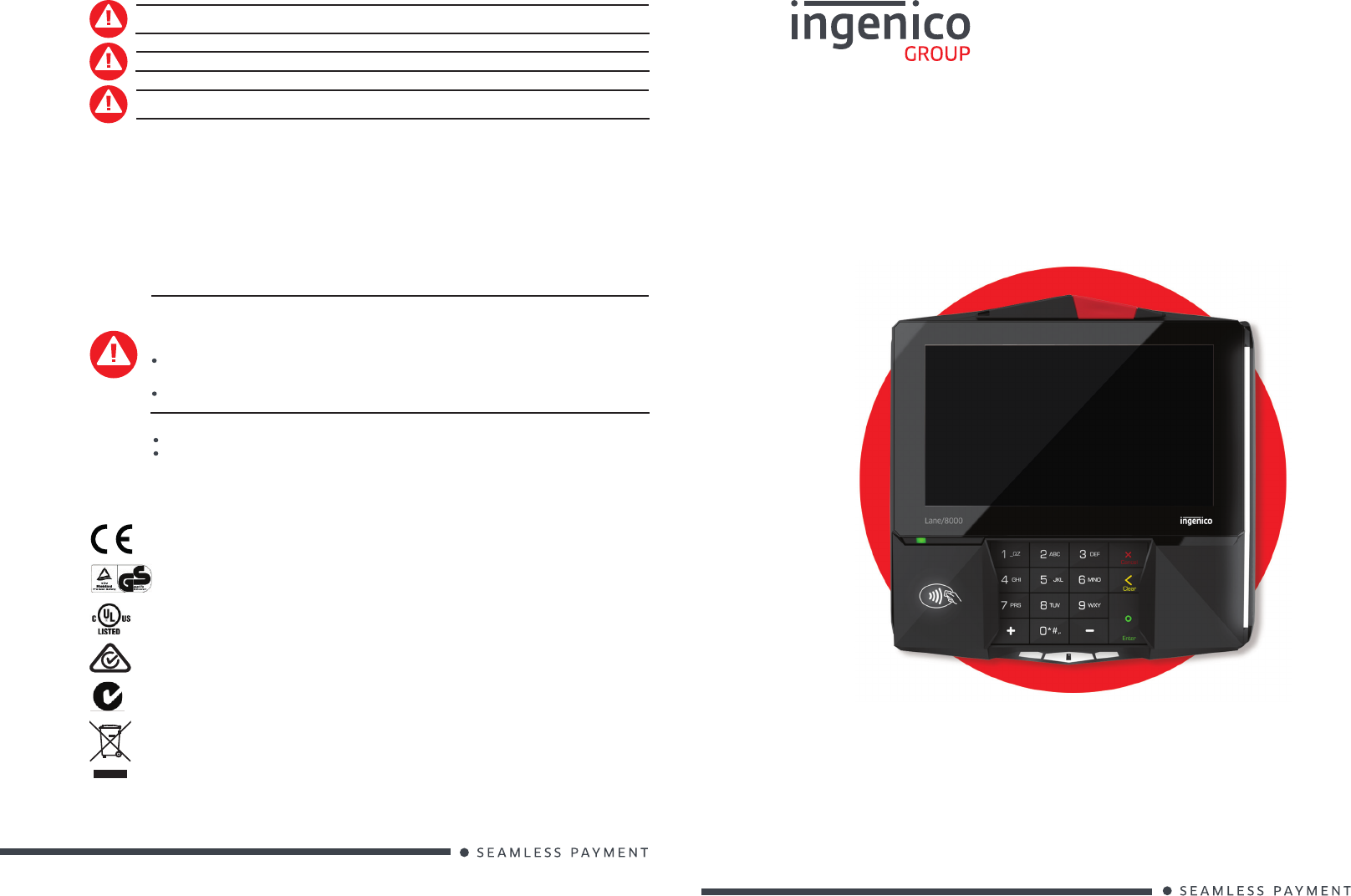
LANE/8000
900028753 R11 000 01/1216
Copyright© 2016 Ingenico
All rights reserved
www.ingenico.com
28-32, boulevard de Grenelle, 75015 Paris - France / (T) +33 (0)1 58 01 80 00 / (F) +33 (0)1 58 01 91 35
Ingenico - SA au capital de 47 656 332 / 317 218 758 RCS Nanterre
Changes or modi cations to this device not expressly approved by the party responsible for compliance could void the
user’s authority to operate the equipment.
Any liquid spill under the custom cover must be removed right away.
The main port at the back must not be used to connect a standard video HDMI cable. Only connect cables provided by
Ingenico.
4_Environment
This product is labelled in accordance with European Directive 2002/96/EC concerning Waste Electrical and Electronic Equipment
(WEEE).
Ingenico ensures that ef cient collection and recycling schemes are set-up for WEEE according to the local regulation of your country.
Please contact your retailers for more detailed information.
Packaging waste must also be collected separately to assure a proper disposal and recycling.
Please note that proper recycling of the WEEE will ensure safety of human health and environment.
More Information
For more information on cleaning, troubleshooting, operating the device, features, speci cations, accessories, the system menu,
security, and downloading see the Ingenico Lane/8000 User Guide.
5_Terminal Location
The Lane/8000 device may be mounted on a at surface, wall, or customer stand (recommended).
The device is designed to operate in the following environment:
Operating temperature of 0°C to 45°C
Operating humidity of 10% to 85% RH non-condensing
The terminal is intended for internal use only.
Do not place the Lane/8000 device on a PC monitor, adjacent to an electronically active security tag deactivation
system, or near other sources of magnetic elds.
The Lane/8000 device must be at least 12 inches away from an electronically active type of security tag deactivation
pad.
There are two types of security tag deactivation systems :
An electronically active system sends out a powerful and potentially disruptive signal to deactivate the security
tag. If the Lane/8000 device is placed too close to the system’s pad, or placed above the pad, the signature capture
les may be corrupted.
A passive system is a permanent magnet type that does not send out a signal. This type does not affect the
Lane/8000 device.
Lane/8000
Installation Guide
The CE marking is the manufacturer’s declaration that the product meets the requirements of the applicable EC
directives. The CE mark is a mandatory conformity marking for certain productssold within the European Economic
Area (EEA).
The RCM mark will be the only mark to indicate compliance with the Australian Communications and Media
Authority’s (ACMA) regulatory arrangements for telecommunications, radio, EMC and electromagnetic energy
(EME).
Waste of Electrical and Electronic Equipment (WEEE) symbol indicates that when the end-user wishes to discard
this product, it must be sent to separate collection facilities for recovery and recycling. By separating this product
from other household-type waste, the volume of waste sent to incinerators or land- lls will be reduced and natural
resources will thus be conserved.
This TÜV symbol shows consumers at a glance that a product has been examined by neutral experts and that there
are no safety concerns
The UL mark appears on end products and complete components suitable for factory and eld installation.
All of the products carrying these marks are coveredby our Follow-Up Services program to determine that products
continue to be manufactured in compliance with UL’s safety requirements.
The C-Tick is an identi cation trademark registered to the Australian Communications Media Authority (ACMA). The
C-Tick mark signi es that the labelled electronic device is compliant with applicable electromagnetic compatibility
(EMC) requirements
FOR PLUGGABLE MODULE, the socket-outlet shall be installed near the equipment and shall be easily accessible.
Lane/8000
900028753 R11 000 01/1216
Lane/8000
900028753 R11 000 01/1216
Copyright© 2016 Ingenico
All rights reserved
Copyright© 2016 Ingenico
All rights reserved
2_Security of your terminal
Your device ful ls current applicable PCI PTS security requirements.
Upon receipt of your terminal you should check for signs of tampering of the equipment. It is strongly advised that these checks
are performed regularly after receipt. You should check, for example: that the keypad is rmly in place; that there is no evidence of
unusual wires that have been connected to any ports on your terminal or associated equipment, the chip card reader or any other
part of your terminal. Such checks would provide warning of any unauthorised modi cations to your terminal, and other suspicious
behaviour of individuals that have access to your terminal. Your terminal detects any “tampered state”. In this state the terminal will
repeatedly ash the message” Alert Irruption!” and further use of the terminal will not be possible. If you observe the “Alert Irruption!”
message, you should contact the terminal helpdesk immediately.
You are strongly advised to ensure that privileged access to your terminal is only granted to staff that have been independently
veri ed as being trustworthy. The terminal must never be put in or left at a location where it could be stolen or replaced by another
device.
CAUTION
Positioning of the Lane/8000 on check stand must be in such a way to make cardholder PIN (Personal Identi cation
Number) spying infeasible.
Installing device on an adjustable stand must be in such a way that consumers can swivel the terminal sideways and/or
tilt it forwards/backwards to a position that makes visual observation of the PIN-entry process dif cult.
Positioning of in-store security cameras such that the PIN-entry keypad is not visible.
NEVER ask the customer to divulge their PIN Code. Customers should be advised to ensure that they are not being
overlooked when entering their PIN Code.
2_1 WARNING TO USERS IN THE UNITED STATES
Federal Communication Commission Interference Statement 47 CFR Section 15.105(b)
This equipment has been tested and found to comply with the limits for a Class B digital device, pursuant to Part 15 of the FCC Rules.
These limits are designed to provide reasonable protection against harmful interference in a residential installation. This equipment
generates uses and can radiate radio frequency energy and, if not installed and used in accordance with the instructions, may
cause harmful interference to radio communications. However, there is no guarantee that interference will not occur in a particular
installation. If this equipment does cause harmful interference to radio or television reception, which can be determined by turning the
equipment off and on, the user is encouraged to try to correct the interference by one of the following measures :
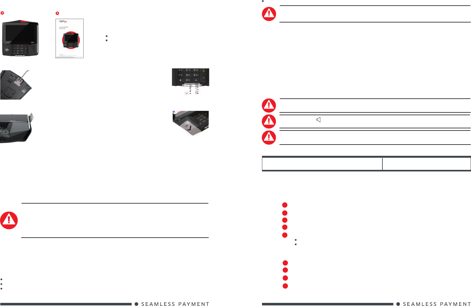
Carefully inspect the shipping carton and its contents for shipping damage. If the device is damaged, le a claim immediately with the
shipping company and notify Ingenico.
You should have :
Lane / 8000 device This guide
Save the carton and packing material for repackaging or moving
the device in the future.
The box may also include the following items depending on your
con guration working :
Power supply unit and Power cord
A stylus
The Lane/8000 magnetic stripe
reader reads debit, credit, and all
standard magnetic stripe cards.
Slide the card from the rear to the
front in a continuous motion for best
results.
Take care to ensure that the
card is inserted in the correct
manner, chip facing up.
Bring the card rmly up to the
active area above the display
(at about 1cm). Keep the card
close to the Reader during the
transaction.
On the back side of the terminal,
there is single connector. Connect
only validated cable. Ensure the
other end provide power and host
communication if required. If needed
connect the power supply to the
mains by the wall receptacle.
1_Equipment check list
1_1 Power & Cable connections
1_2 Magnetic Stripe Reader
1_3 Smart Card Reader
1_4 Contacless Reader
Reorient or relocate the receiving antenna.
Increase the separation between the equipment and receiver.
Connect the equipment into an outlet on a circuit different from that to which the receiver is connected.
2_3 ANTENNA REQUIREMENT
Federal Communication Commission Interference Statement 47 CFR Section 15.203
This device complies with Part 15 of the FCC Rules. Operation is subject to the following two conditions: (1) This device may not cause
harmful interference, and (2) this device must accept any interference received, including interference that may cause undesired
operation.
2_4 WARNING TO USERS IN THE CANADA
This device complies with Industry Canada licence-exempt RSS standard(s). Operation is subject to the following two conditions: (1) this
device may not cause interference, and (2) this device must accept any interference, including interference that may cause undesired
operation of the device.
Under Industry Canada regulations, this radio transmitter may only operate using an antenna of a type and maximum (or lesser) gain
approved for the transmitter by Industry Canada.
To reduce potential radio interference to other users, the antenna type and its gain should be so chosen that the equivalent isotropically
radiated power (e.i.r.p.) is not more than that necessary for successful communication.
CAUTION
Risk of explosion if the battery is replaced by an incorrect type. Dispose of used battery according to the instructions
Connection of headset on audio output jack:
An excessive acoustic pressure of headset can involve deafness!
Only use the power supply AC/DC provided with Lane/8000 (8VDC 2A or 8VDC 3A) or the power provided by a cash
register (16 Watt min, 8V min) limited power source (LPS) or (10W, 5V).
Remove the power jack to power off the terminal.
Authorized power supply units :
PHIHONG TECHNOLOGY Co. Ltd PSM24W-080L6IN-R
3_Troubleshooting
3_1 Magnetic Card Reader Does Not Work Properly
1When sliding the card through the reader, make sure that the magnetic stripe on the card is facing the Lane/8000
display screen (see Magnetic Stripe Reader).
Swipe the card at a faster or middle steady speed.
2
Inspect the magnetic stripe on the card to make sure it is not scratched or badly worn.
3
CAUTION
This equipment may not be modi ed, altered, or changed in any way without signed written permission from Ingenico.
Unauthorized modi cation may void the equipment authorization from the FCC and will void the Ingenico warranty.
Consult the dealer or an experienced radio/TV technician for help.
2_2 NO AUNAUTHORIZED MODIFICATIONS
Federal Communication Commission interference Statement 47 CFR Section 15.21
2_5 SAFETY
Security tag deactivation system could disturb the magnetic card reader
4
If your host device has a magnetic stripe reader, try swiping the card there.
If you have another working Lane/8000 device, try swiping the card there.
To determine if the problem is with the card:
5
3_2 Device is not working
Make sure that the Lane/8000 connector is fully inserted into the back of the device.
1
Restart the device.
2
If you have another working Lane/8000 device, swap the devices to determine if the problem is with the device,
cable, POS, or power supply.
3
If the Lane/8000 device is directly connected to a host, reset the host by turning it off and back on again.
4