Ingenu ULPAP110 ACCESS POINT User Manual Access Point
On-Ramp Wireless ACCESS POINT Access Point
UserManual.wiki
>
Ingenu
>
ULPAP110 User Manual
>
user manual
Contents
1.
user manual
2.
antenna information gps
3.
antenna information rf
4.
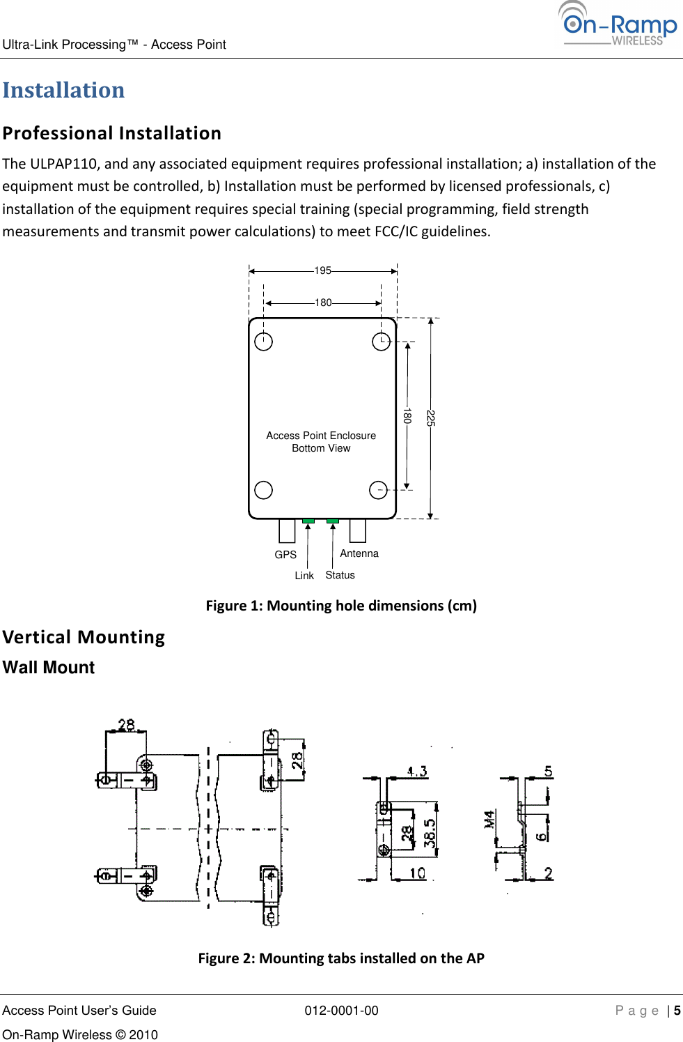
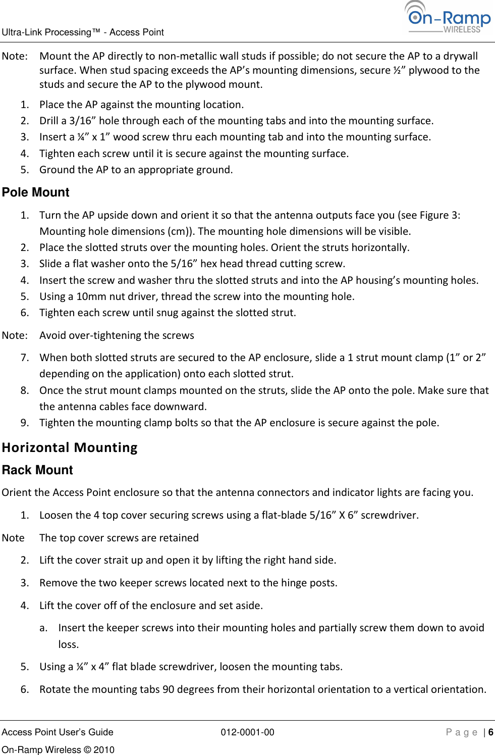
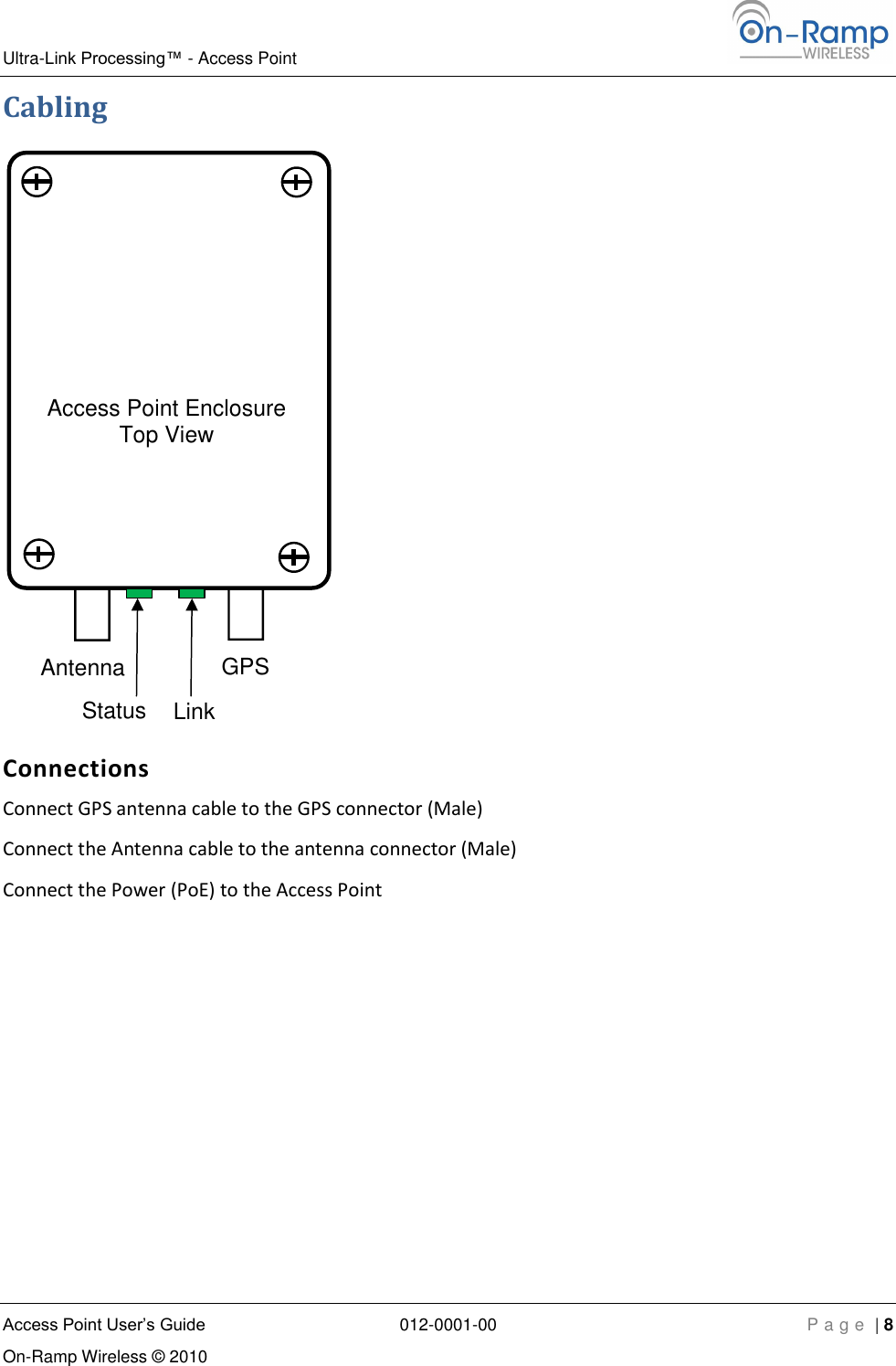
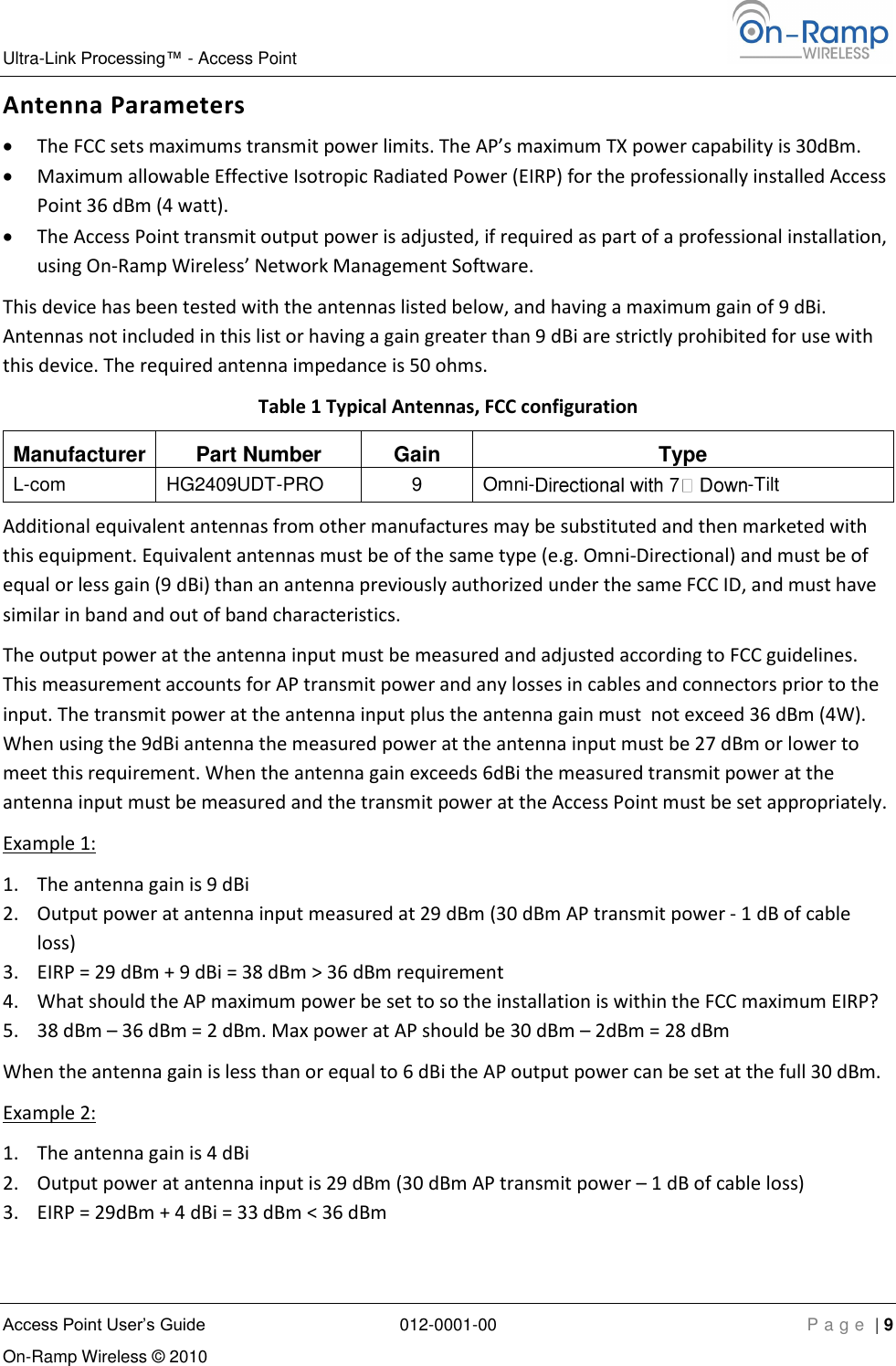
User Manual
user manual
Navigation menu
Upload a User Manual
Namespaces
Wiki Guide
HTML
PDF
Info
Views
User Manual
Discussion / Help
Navigation