Ingenu ULPENODE120 On-Ramp Wireless eNode User Manual eNode
On-Ramp Wireless On-Ramp Wireless eNode eNode
UserManual.wiki
>
Ingenu
>
ULPENODE120 User Manual
User manual
Navigation menu
Upload a User Manual
Namespaces
Wiki Guide
HTML
PDF
Info
Views
User Manual
Discussion / Help
Navigation
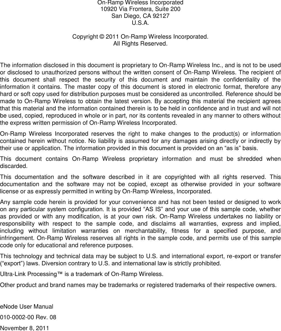
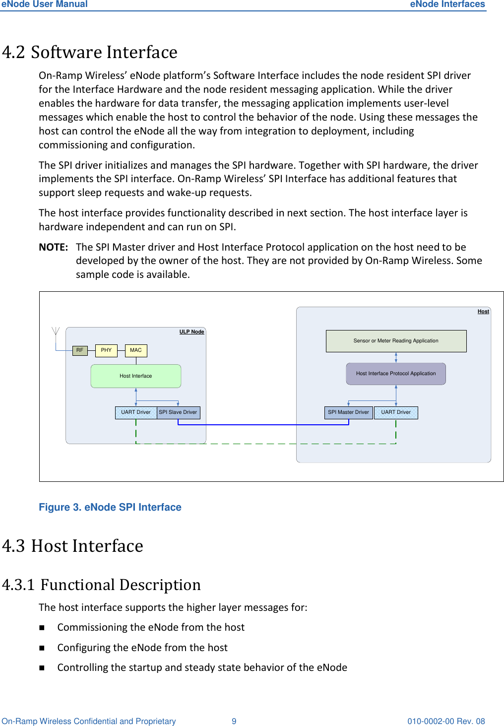
![eNode User Manual eNode Interfaces On-Ramp Wireless Confidential and Proprietary 10 010-0002-00 Rev. 08 Transferring payload data to and from the host Upgrading the Software on the eNode. [Future releases] Executing a set of diagnostic tests on the eNode. [Future releases] Collecting debug data from the eNode. [Future releases] The messages can be broadly classified as Debug, Configuration, and User Data messages. 4.3.2 Host Interface Protocol On-Ramp Wireless’ ULP eNode’s host interface supports reliable transfer of messages between the host and eNode over SPI. To support this functionality: Explicit ‘Connect’ and ‘Disconnect’ messages are supported. Each host-to-node message is acknowledged. This is useful in reliability and also for back-pressure, where the host needs to slow down or stop sending messages to the eNode. The node-to-host messages do not have any acknowledgements. The eNode will not wait for acknowledgements. The eNode expects the host to be able to receive all messages and keep up with the eNode. For the SPI interface, the host (being the SPI master) is expected to be fast enough so as to not block various operations at the eNode. If this is violated, the eNode will miss RX/TX events. The SPI driver provides methods for basic bit/byte transport. To do that there are SPI message requests, SPI message headers and SPI payload. The SPI payload contains the host interface message. 4.3.3 Signal Description Table 2. eNode SPI Signal Definition Pin Name Pin Description Type Master Slave MISO Master In Slave Out In Out MOSI Master Out Slave In Out In SCLK Serial Clock Out In SS Slave Select Out In MRQ Master Request Out In SRDY Slave Ready In Out SRQ Slave Request In Out 4.3.4 Master Request / Slave Ready Before initiating transfers to and from the node, the host must ensure the node is awake and ready to receive SPI traffic by driving MRQ high and waiting for the node SPI slave to drive SRDY](https://usermanual.wiki/Ingenu/ULPENODE120/User-Guide-1588293-Page-15.png)