Ingenu ULPT100 ULP Tracker User Manual ULP EMS Operator Guide
On-Ramp Wireless ULP Tracker ULP EMS Operator Guide
Ingenu >
Exhibit 08 Users Manual

On-Ramp Wireless Confidential and Proprietary. This document is not to be used, disclosed, or distributed to
anyone without express written consent from On-Ramp Wireless. The recipient of this document shall respect the
security of this document and maintain the confidentiality of the information it contains. The master copy of this
document is stored in electronic format, therefore any hard or soft copy used for distribution purposes must be
considered as uncontrolled. Reference should be made to On-Ramp Wireless to obtain the latest revision.
ULP EMS Operator
Guide
On-Ramp Wireless Incorporated
10920 Via Frontera, Suite 200
San Diego, CA 92127
U.S.A.
Copyright © 2011 On-Ramp Wireless Incorporated.
All Rights Reserved.
The information disclosed in this document is proprietary to On-Ramp Wireless Inc., and is not to be used
or disclosed to unauthorized persons without the written consent of On-Ramp Wireless. The recipient of
this document shall respect the security of this document and maintain the confidentiality of the
information it contains. The master copy of this document is stored in electronic format, therefore any
hard or soft copy used for distribution purposes must be considered as uncontrolled. Reference should be
made to On-Ramp Wireless to obtain the latest version. By accepting this material the recipient agrees
that this material and the information contained therein is to be held in confidence and in trust and will not
be used, copied, reproduced in whole or in part, nor its contents revealed in any manner to others without
the express written permission of On-Ramp Wireless Incorporated.
On-Ramp Wireless Incorporated reserves the right to make changes to the product(s) or information
contained herein without notice. No liability is assumed for any damages arising directly or indirectly by
their use or application. The information provided in this document is provided on an “as is” basis.
This document contains On-Ramp Wireless proprietary information and must be shredded when
discarded.
This documentation and the software described in it are copyrighted with all rights reserved. This
documentation and the software may not be copied, except as otherwise provided in your software
license or as expressly permitted in writing by On-Ramp Wireless, Incorporated.
Any sample code herein is provided for your convenience and has not been tested or designed to work
on any particular system configuration. It is provided “AS IS” and your use of this sample code, whether
as provided or with any modification, is at your own risk. On-Ramp Wireless undertakes no liability or
responsibility with respect to the sample code, and disclaims all warranties, express and implied,
including without limitation warranties on merchantability, fitness for a specified purpose, and
infringement. On-Ramp Wireless reserves all rights in the sample code, and permits use of this sample
code only for educational and reference purposes.
This technology and technical data may be subject to U.S. and international export, re-export or transfer
(“export”) laws. Diversion contrary to U.S. and international law is strictly prohibited.
Ultra-Link Processing™ is a trademark of On-Ramp Wireless.
Other product and brand names may be trademarks or registered trademarks of their respective owners.
ULP EMS Operator Guide
010-0045-00
June 8, 2011

On-Ramp Wireless Confidential and Proprietary iii 010-0045-00
Contents
1 Introduction ........................................................................................................... 1
2 ULP Network Overview ......................................................................................... 3
3 Maintaining and Operating the ULP Network ..................................................... 5
3.1 Logging in to the EMS ................................................................................................................ 5
3.2 Types of Accounts...................................................................................................................... 6
3.3 Maintaining a Local Account ...................................................................................................... 7
3.3.1 Adding a User Account ..................................................................................................... 8
3.3.2 Editing a User Account ..................................................................................................... 9
3.4 Configuring the ULP Network .................................................................................................... 9
3.4.1 Configuring the Network with the Ingest File - Initialization Steps ................................. 10
3.4.2 Configuring the Gateway with the Ingest File ................................................................. 10
3.4.3 Restarting the Gateway .................................................................................................. 11
3.4.4 Configuring Access Points with the Ingest File .............................................................. 11
3.5 Configuring the Network Manually ........................................................................................... 13
3.5.1 Adding the Gateway ....................................................................................................... 13
3.5.2 Configuring ULP Network Parameters ........................................................................... 15
3.5.3 Enabling the Gateway .................................................................................................... 20
3.5.4 Configuring an Access Point .......................................................................................... 20
3.5.5 Configuring an End Device ............................................................................................. 29
3.5.6 Adding an End Device .................................................................................................... 30
3.5.7 Configuring a Specific Device Update Interval (UI) or Listen Interval (LI) ...................... 31
3.6 Day to Day Operations ............................................................................................................. 35
3.6.1 Summary of Alarms ........................................................................................................ 36
3.6.2 Configuring Alarm Emails ............................................................................................... 43
3.6.3 Details of the Alarm Console .......................................................................................... 46
3.6.4 Acknowledging Alarms ................................................................................................... 48
3.6.5 EMS Alarm History ......................................................................................................... 50
3.7 Audit Reporting ........................................................................................................................ 52
Appendix A Typical Email Alert Alarm Email ...................................................... 54
Appendix B New Application Types ..................................................................... 57
Appendix C Abbreviations and Terms ................................................................. 59

ULP EMS Operator Guide Contents
On-Ramp Wireless Confidential and Proprietary iv 010-0045-00
Figures
Figure 1. EMS UI Terminology ......................................................................................................... 2
Figure 2. Functional Overview of the ULP Network ......................................................................... 3
Figure 3. NODE FREQUENT REJOIN Alarm Email ...................................................................... 54
Figure 4. Reminder for the Alarm ................................................................................................... 55
Figure 5. Acknowledgement of the Alarm ...................................................................................... 55
Figure 6. Email Showing the Cleared Alarm .................................................................................. 56
Tables
Table 1. Sysmon UI and LI Values ................................................................................................ 33
Table 2. FCI UI and LI Values ........................................................................................................ 33
Table 3. RMU UI and LI Values ..................................................................................................... 34
Table 4. Alarm Type and Severity, Description, and Clearing Condition ....................................... 36

On-Ramp Wireless Confidential and Proprietary v 010-0045-00
Revision History
Revision
Release Date
Change Description
01
December 10, 2010
Initial release of operator guide complete to system release
1.2.4.7.
02
December 13, 2010
Updated to be consistent with system release 1.2.5.2. Changes
include:
Screenshots for active directory
Minor changes to procedure for adding and starting up APs
03
May 3, 2010
Updated to be consistent with system release 1.2.5.13. Changes
include:
Updated screenshots
Minor changes to procedures for adding a Gateway (GW), an
AP, and nodes
Expanded alarm table
Added section in alarm table for Audit Reporting
04
May 26, 2010
Updated to be consistent with system release 1.2.5.17. Changes
include:
Updated screenshots
Added Email alert examples
Added Appendix B

On-Ramp Wireless Confidential and Proprietary 1 010-0045-00
1 Introduction
This document provides Element Management System (EMS) administrators and/or operators
with the following information:
EMS account configuration and maintenance.
Ultra-Link Processing™ (ULP) network commissioning and configuration.
ULP end device commissioning and configuration.
Day to day network operation, including network alarm monitoring and network alarm
acknowledgment.
This document does not provide EMS administrators and/or operators with the following
information:
Gateway hardware or software installation.
Critical Infrastructure Monitoring Application (CIMA) hardware or software installation.
EMS hardware or software installation.
End device application descriptions.
Install and configure the software and/or hardware for each network component before using
the instructions in this document.
NOTE:
The On-Ramp Wireless Network Management System (NMS) software is going through
the process of a name change from NMS to EMS (Element Management System).
During this process, NMS and EMS are used interchangeably.
ULP EMS Operator Guide Introduction
On-Ramp Wireless Confidential and Proprietary 2 010-0045-00
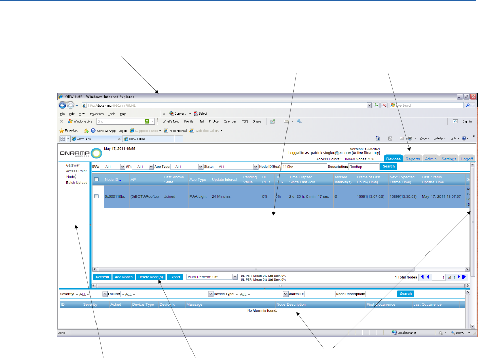
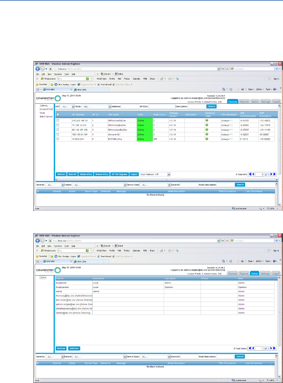
The following figure displays the EMS User Interface (UI) terminology.
Screen
Device Listing Pane
Device Selection Pane
Alarm Pane
Note:
You may need to use the slider to see the
entire Alarm Pane.
Tab
Button
Figure 1. EMS UI Terminology
NOTE:
The previous figure shows the EMS UI which contains panes and tabs with a drop-down
list (Auto Refresh: OFF). Use this drop-down list to control the refresh rate of the
screen.
On-Ramp Wireless Confidential and Proprietary 3 010-0045-00
2 ULP Network Overview
The On-Ramp Wireless ULP technology network monitors critical infrastructure devices in a
wide-area territory. A network deployment contains many Access Points (APs) that are
geographically distributed in a specific territory. The APs create a wireless network which
monitors end devices. End devices can include:
Federal Aviation Administration (FAA) obstruction light Remote Monitoring Units (RMUs)
Distribution line Fault Circuit Indicators (FCIs)
The ULP network provides advantages for wide area sensor networking. The ULP network
enables powered and battery operated Transmission and Distribution Smart and Remote
Monitoring applications. The ULP network is deployed in an infrastructure efficient star topology
and operates at -142 dBm receive sensitivity. Operating at this level provides a 40dB link budget
advantage over competitive technologies. The ULP network, combined with a unique, multiple
access scheme, services hundreds of thousands of sensors on a network. The ULP network is
deployed in above-ground, pad-mount, and below-ground applications. The link budget
advantage allows a ULP system to reliably operate in the unlicensed 2.4 GHz ISM band. This
eliminates spectrum and recurring data service charges. The link budget advantage also provides
utility companies with a network that meets the performance and security requirements of the
critical infrastructure.
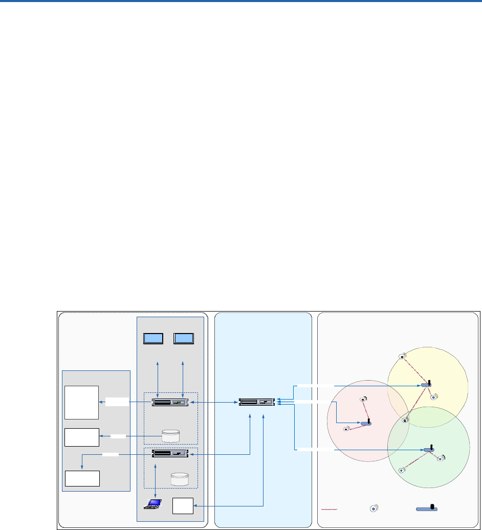
The following figure illustrates the functional overview of the ULP network.
Network Communications
Aviation Lights
ULP Node ULP Access PointULP Link
ULP Gateway
Back Office Service Area
Radio Fault
Indicators
Aviation
Lights
Radio Fault
Indicators
Aviation
Lights
Aviation Lights
Radio Fault
Indicators
Element Mgmt System
(EMS)
Oracle
Database
Critical Infrastructure
Monitoring Application
(CIMA)
ORW Back Office
Oracle
Database
KMS
Data
Warehouse
NMS
Operator Back Office
ETL
SNMP
XML
Interface
Dashboard
Aviation
Lights
Dashboard
Dist Ops
Center
EMS View
OMS/DMS
Secure IP Backhaul
Secure IP Backhaul
Secure IP Backhaul
Figure 2. Functional Overview of the ULP Network
The On-Ramp Wireless EMS provides network control and alarm status for the ULP Gateway
(GW), APs, and end devices in the network.

ULP EMS Operator Guide ULP Network Overview
On-Ramp Wireless Confidential and Proprietary 4 010-0045-00
NOTE:
Operators can use the On-Ramp Wireless CIMA and dashboard for application-level
data collection and application alarms.
On-Ramp Wireless Confidential and Proprietary 5 010-0045-00
3 Maintaining and Operating the ULP Network
The following sections describe how to maintain and operate the ULP network through the On-
Ramp Wireless EMS.
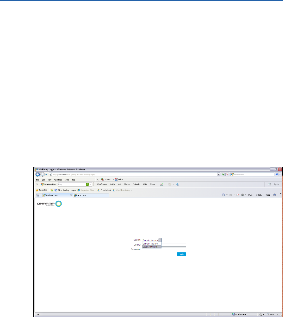
3.1 Logging in to the EMS
To log in to the EMS, complete the following steps:
1. Open a web browser, and type:
http://<ip address of the EMS server or DNS name>:8080/nms
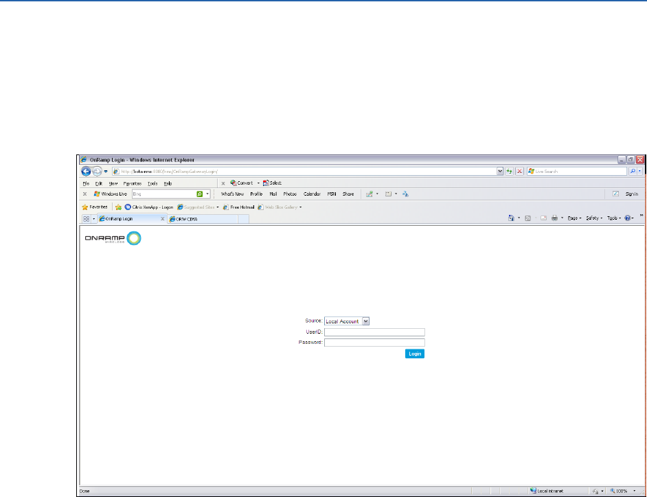
2. From the Source drop-down list, select company Domain or Local Account. Typically, it is
expected that installations use the Active Directory.
Active Directory use is enabled during EMS installation. See the EMS Software
Installation Guide for more information on Active Directory setup.
If the drop-down list is not visible, the Active Directory configuration is not set up. Log in
with local account access with an account that was created in Maintaining a Local
Account.
3. In the UserID field, type the user ID for this account.
NOTE:
Use the Active Directory account password when logging in to the EMS through the
company Domain. If the company Domain is not active, use an account that was
created in Maintaining a Local Account.
ULP EMS Operator Guide Maintaining and Operating the ULP Network
On-Ramp Wireless Confidential and Proprietary 6 010-0045-00
4. In the Password field, type the password for this account.
NOTE:
Use the Active Directory account password when logging in to the EMS through the
company Domain. If the company Domain is not active, use an account that was
created in Maintaining a Local Account.
5. Click Login.
3.2 Types of Accounts
The EMS contains the following types of accounts:
Admin
Operator
Guest
When a user account is created, each additional account that is created in the EMS system is
created as an admin, an operator, or a guest account. These account types exist for both Local
Accounts and Active Directory enabled systems.
When configuring Local Accounts, the Local Account administrator creates and maintains
the accounts.
When using Active Directory, the company's Information Technology (IT) group is
responsible for setting up the EMS accounts. In this case, accounts are created according to
account type (admin, operator, or guest) and are mapped to the Active Directory. For more
information, see the EMS Software Installation Guide.

ULP EMS Operator Guide Maintaining and Operating the ULP Network
On-Ramp Wireless Confidential and Proprietary 7 010-0045-00
The following sections describe each type of account in the EMS.
Administrator Account
In new EMS installations that are not using Active Directory controlled logins, the administrator
(admin) account is the only default account available. The admin account only manages
accounts created in Local Accounts. If using Active Directory, the internal company's IT group
maintains the account. For Local Account login, the default UserID is admin, and the default
password is onramp.
The administrator account has complete control over the network configuration, network
operation, and Local Account administration. When using Active Directory, the IT group that
controls the Active Directory also controls the creation of accounts. If this is the first time that a
system administrator logs in to the EMS system, the system administrator should change the
default account password for the local default admin account.
It is recommended that the administrator:
Change the default password for the local default admin account.
Create an account for all other EMS operators that have access to the system and do not
regularly use the default admin account for day to day operations, when using Local
Accounts.
For day to day operations in the EMS system, it is recommended that the administrator create
operator type accounts.
Operator Account
The operator type of account allows operators to configure the network end device network
parameters. If operators log in to the system as a user with this type of account, EMS account
administration cannot be performed.
Guest Account
The guest type of account allows guest account users to monitor the network operation.
When logging in to the EMS, different tabs display for different types of accounts. For example,
when logging in to the EMS with an administrator account, the tabs that display are different
than those of a read-only account.
3.3 Maintaining a Local Account
The following sections describe how to add and edit local user accounts in the EMS.
ULP EMS Operator Guide Maintaining and Operating the ULP Network
On-Ramp Wireless Confidential and Proprietary 8 010-0045-00
3.3.1 Adding a User Account
To add a local EMS user account, log in with an administrator account, and complete the
following steps:
1. On the login screen, click the Admin tab.
2. Click Add User.

ULP EMS Operator Guide Maintaining and Operating the ULP Network
On-Ramp Wireless Confidential and Proprietary 9 010-0045-00
3. In the User ID field, type the user ID for this account. This is the same user ID that is entered
when logging in to the EMS with this new account.
4. In the First Name field, type the first name of the user for this account.
5. In the Last Name field, type the last name of the user for this account.
6. In the Password field, type the password for this account.
7. In the Confirm Password field, confirm the password entered above.
8. In the Phone field, type the phone number for the user for this account.
9. From the Assigned Role drop-down list, select the account type to use for this account.
10. Click Save.
NOTE:
A pop-up window may display depending on the password complexity used in Step 6
and Step 7 above. Make sure that the assigned password meets the password
complexity rules as described in the pop-up window.
3.3.2 Editing a User Account
To edit a user account, complete the following steps:
1. Log in to the EMS with an administrator account.
2. Click on the account to edit.
3. Change the account information.
4. Click Save.
3.4 Configuring the ULP Network
To configure the ULP network, configure and commission the following ULP elements:
Gateway
APs
End devices (nodes)
To configure the ULP network, log in with an admin or configure account. When logging in with a
read-only account, the ULP network cannot be configured.
Operators can use the following methods to initialize the network:
Ingest file
Manual configuration
Operators can use a combination of these methods to initialize a network. For example, an
operator can start to initialize a network deployment of a small number of APs and nodes with
an ingest file. As APs and nodes are added to the network, the operator can add them through a
manual configuration.
ULP EMS Operator Guide Maintaining and Operating the ULP Network
On-Ramp Wireless Confidential and Proprietary 10 010-0045-00
The method in which operators use to initialize a network depends on the following items:
Complexity of the operator's network
Availability of site-specific information at the time of initialization
3.4.1 Configuring the Network with the Ingest File - Initialization
Steps
To configure the ULP network with the ingest file method, the operator must first have a valid
ingest file. On-Ramp Wireless provides operators with a valid ingest file to configure the ULP
network. The following example describes how to bring up a network from a single ingest file
that contains information for a Gateway and an AP.
To use the valid ingest file, complete the following steps:
1. Read in an ingest file to configure the Gateway.
2. Read in an ingest file to configure the AP.
3. Read in an ingest file to configure the end device.
3.4.2 Configuring the Gateway with the Ingest File
To configure the Gateway with the ingest file, complete the following steps:
1. Log in to the EMS with an admin account.
2. Click the Devices tab.
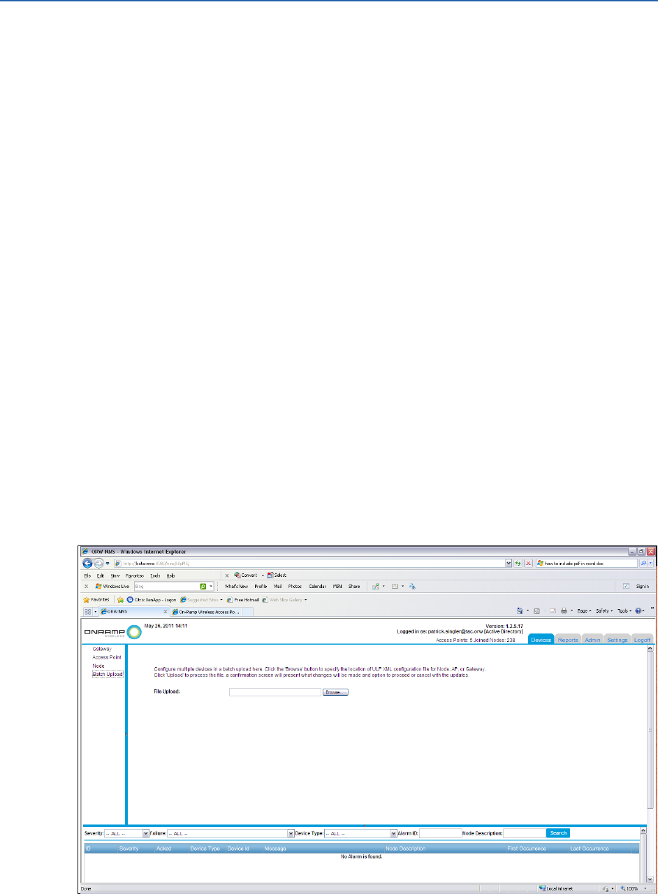
3. In the Devices pane, click Batch Upload.

ULP EMS Operator Guide Maintaining and Operating the ULP Network
On-Ramp Wireless Confidential and Proprietary 11 010-0045-00
4. Click Browse, and navigate to the location of the ingest file.
5. Click Upload.
6. Click Save. The pop-up window asks the operator to confirm the configuration of the
Gateway.
7. Click Yes.
3.4.3 Restarting the Gateway
After uploading the ingest batch file, restart the Gateway.
To restart the Gateway, complete the following steps:
1. In the Devices pane, click Gateway.
2. Select the Gateway to restart, and click Restart Gateway. The pop-up window asks the
operator to confirm the restart.
3. Click Yes.
3.4.4 Configuring Access Points with the Ingest File
To configure access points with the ingest file, complete the following steps:
1. Log in to the EMS with an admin account.
2. Click the Devices tab.
3. Click Batch Upload.
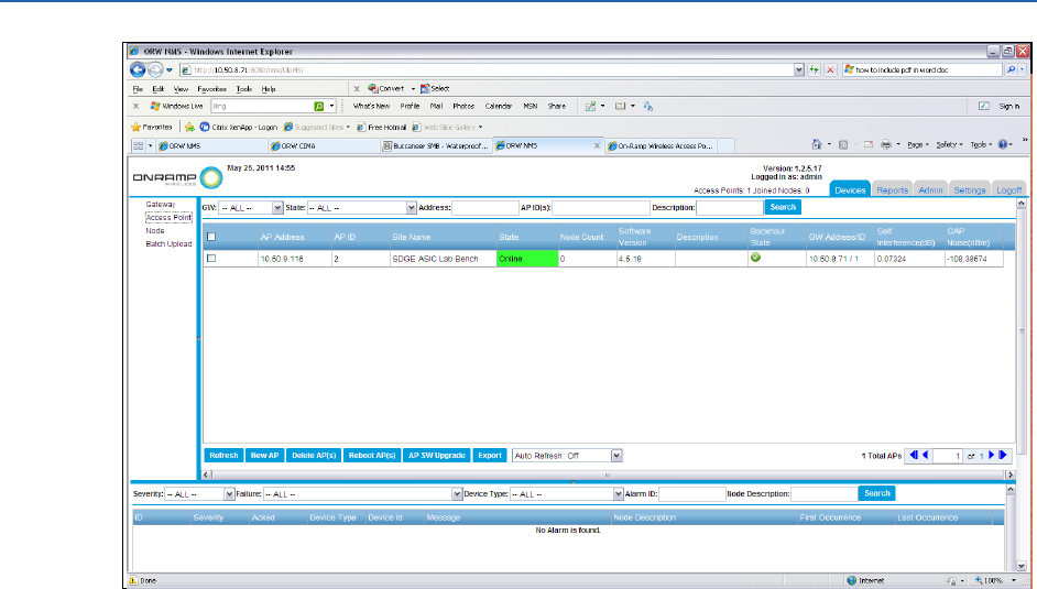
4. To start the AP, reload the configuration file, upload, save, and confirm the upload.
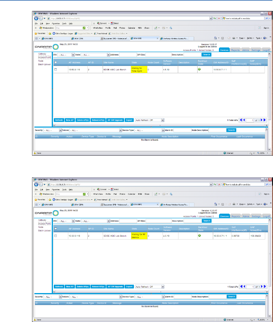
5. To confirm the status of the AP, select Devices Access Point in the Devices pane.
NOTE:
The EMS AP status does not update immediately. Eventually, the status shows that
the AP has transitioned to a yellow state. Alternatively, the operator can click
Refresh from the Access Point Device Listing screen. Depending on when the screen
is refreshed, the operator will see Waiting for Time Sync or Waiting for RF Metrics
display in the State field. This is normal behavior for an AP that is transitioning from
an offline state to an online state. The AP goes through an initialization period in
which it first finds GPS and then measures the RF noise that the AP experiences.
During this process, the AP adjusts the RF behavior accordingly. Typically, this
adjustment takes approximately 2.5 minutes to complete.
ULP EMS Operator Guide Maintaining and Operating the ULP Network
On-Ramp Wireless Confidential and Proprietary 12 010-0045-00
ULP EMS Operator Guide Maintaining and Operating the ULP Network
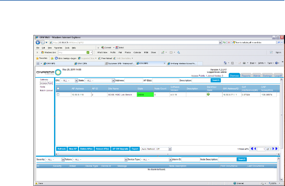
On-Ramp Wireless Confidential and Proprietary 13 010-0045-00
6. After the AP adjusts the GPS time sync and RF Metrics, the AP transitions from a yellow
state to a green state as shown below.
3.5 Configuring the Network Manually
The following sections describe how to perform a manual network configuration.
3.5.1 Adding the Gateway
The ULP Gateway is the point of entry for configuring the ULP network. After logging in to the
EMS, add the Gateway before configuring the other ULP elements, such as APs and/or Nodes.
ULP EMS Operator Guide Maintaining and Operating the ULP Network
On-Ramp Wireless Confidential and Proprietary 14 010-0045-00
To add and/or configure the Gateway, complete the following steps:
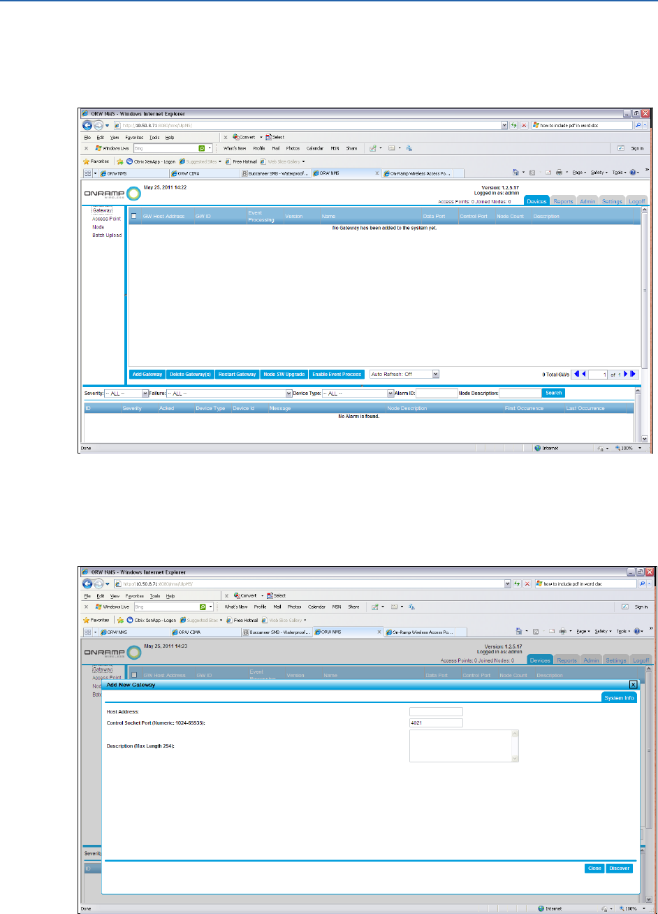
1. After logging in to the EMS, click the Devices tab, and select Gateway from the Device
Selection pane.
NOTE:
For a new network, preconfigured Gateways, access points, and/or nodes will not be
displayed.
2. Click Add Gateway.
ULP EMS Operator Guide Maintaining and Operating the ULP Network
On-Ramp Wireless Confidential and Proprietary 15 010-0045-00
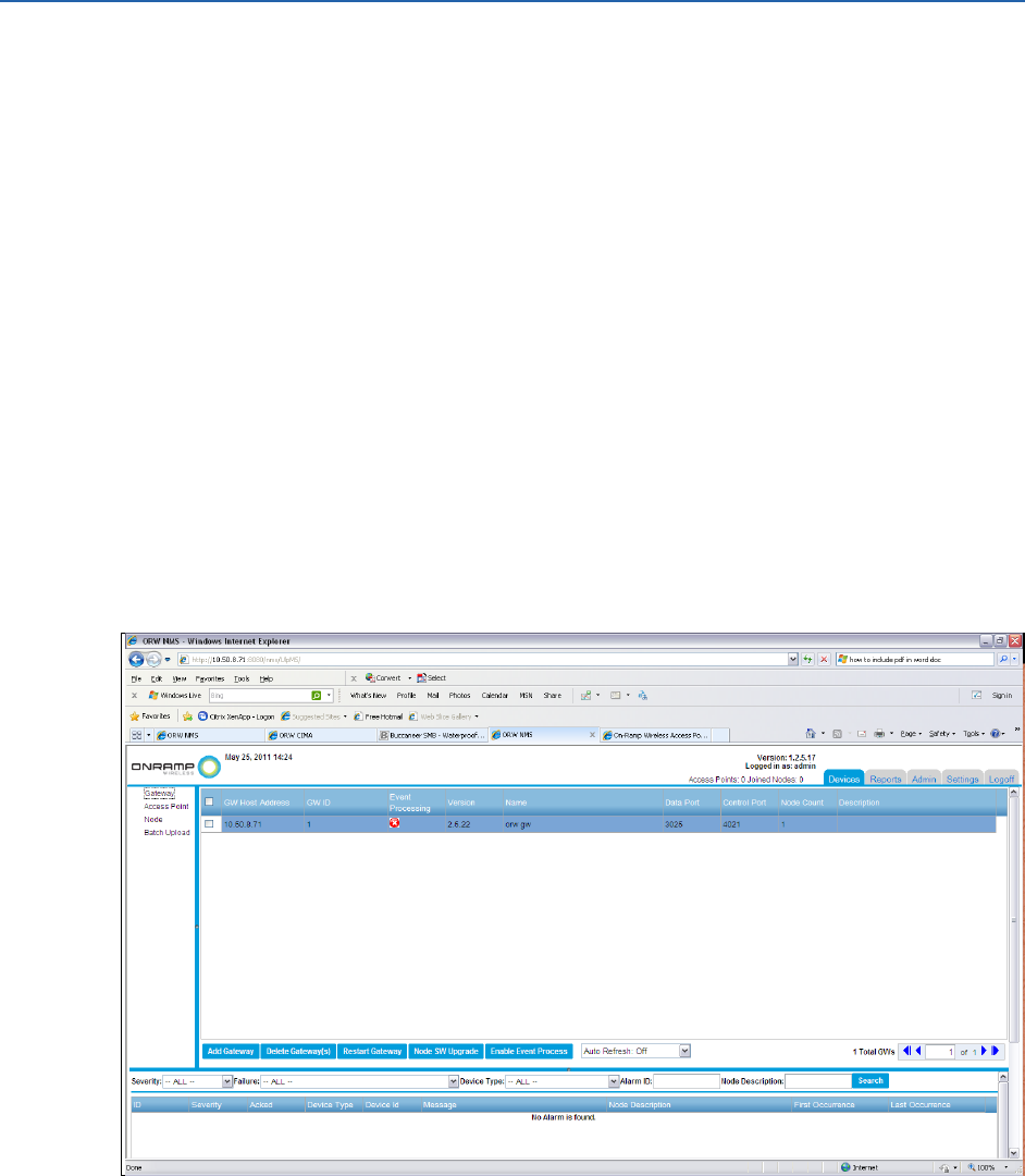
3. In the Add New Gateway window, complete the information for the following fields.
a. In the Host Address field, type the IP address (or DNS resolvable name) for the machine
running the ULP Gateway.
b. In the Control Port field, the default value is 4021. Do not change this value.
c. Optional: In the Description field, type a description for the Gateway. The description
can be any user-specific information, such as physical location or internal name for the
Gateway.
4. Click Discover. A warning box displays alerting that the Gateway will not be updated in the
EMS until the Gateway is enabled.
5. Click OK.
3.5.2 Configuring ULP Network Parameters
Operators must configure ULP network parameters before enabling the Gateway in the system.
To configure the ULP network parameters, complete the following steps:
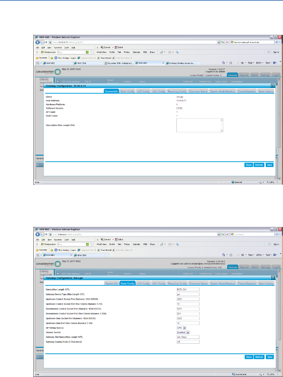
1. In the Devices selection pane, select Gateway. The Gateway that was added is displayed.
ULP EMS Operator Guide Maintaining and Operating the ULP Network
On-Ramp Wireless Confidential and Proprietary 16 010-0045-00
2. In the Device selection pane, click on the GW ID of the Gateway that was added. The
Gateway Configuration window is displayed.
3. Optional: In the Description field, type a description for the Gateway. The description can be
any user-specific information, such as physical location or internal name for the Gateway.
4. Click the Basic Config tab.

ULP EMS Operator Guide Maintaining and Operating the ULP Network
On-Ramp Wireless Confidential and Proprietary 17 010-0045-00
5. In the Gateway Configuration window, complete the information for the following fields.
a. In the Name field, type a descriptive name for this Gateway.
b. In the Gateway Device Type field, type gw.
c. In the Upstream Control Socket Port (Numeric: 1024-65535) field, the default value is
4021. If the network does not use the default value, update the port value.
d. In the Upstream Control Socket Port Max Clients (Numeric 5-10) field, type 10.
e. In the Downstream Control Socket Port (Numeric: 1024-65535) field, type 5051.
f. In the Downstream Control Socket Port Max Client (Numeric: 1-254) field, type 254.
g. In the Upstream Data Socket Port (Numeric: 1024-65535) field, type 3025.
h. In the Upstream Data Port Max Clients (Numeric 5-10) field, type 10.
i. In the AP Timing Source field, select GPS from the drop-down list.
j. In the Secure Socket field, select enabled from the drop-down list.
k. In the Gateway Site Name (Max Length 127) field, type the site name for the Gateway.
l. In the Gateway Country Code (2 Characters) field, type the country code for the
Gateway.
m. Click Save.
NOTE:
If the operator has not changed any of the default settings and has clicked Save, the
following warning displays:
Cannot save configuration. No change has been made.
If changes have been made, a pop-up window asks for confirmation to restart.
Additionally, there is a place to enter an optional note about this configuration
change. All EMS configuration changes are logged to an audit report. The
information here is logged in this report with the configuration change.
6. The pop-up window asks the operator to confirm the restart.
7. Click Yes. The pop-up window asks the operator to confirm the restart.
8. Click Yes.
9. In the Device selection pane, click on the GW ID of the Gateway that was added. The
Gateway Configuration window is displayed.
ULP EMS Operator Guide Maintaining and Operating the ULP Network
On-Ramp Wireless Confidential and Proprietary 18 010-0045-00
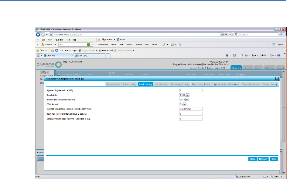
10. Click the ULP Config tab.
11. In the Gateway Configuration window, complete the information for the following fields.
a. In the System ID (Numeric 0-255) field, type the operator-specific System ID that
matches the operator's network system ID.
b. In the Bandwidth field, the default value (1MHz) is selected from the drop-down list. Do
not change this value.
c. In the Broadcast Spreading Factor field, select 2048 from the drop-down list. The
default value is 2048.
d. In the OTA Security field, select On from the drop-down list.
NOTE:
Typically, for a production system, select On. For a lab and/or a developmental
system, the operator may optionally select Off.
If OTA Security is turned On, the operator must provision Gateway and node keys
for the operator's system to function properly. For information on how to set up
security keys, see the KMS User Guide.
The Key Management Server (KMS) should be up and running before configuring
other pieces of the system.
e. In the Current Regulatory Domain (Max Length 256) field, type the name of the
operator's current regulatory domain.
f. In the Root Key Roller Interval (Numeric 0-65535) field, type 30.
NOTE:
Based on the operator's local information security requirements, this number
may be different from the default number (30). If it is different, enter it now.
ULP EMS Operator Guide Maintaining and Operating the ULP Network
On-Ramp Wireless Confidential and Proprietary 19 010-0045-00
g. In the Keep Alive Message Interval (Seconds 5-60) field, type 5.
NOTE:
This parameter affects the generation of the GW Health alarm that the EMS
generates. If the GW has not generated a keep alive signal within 3*<number of
seconds> in this field, the GW Health alarm will be triggered.
12. Click Save.
NOTE:
A pop-up window asks the operator to confirm the restart. Additionally,
there is a place to enter an optional note about this configuration change.
All EMS configuration changes are logged to an audit report. The
information here is logged in this report with the configuration change.
13. A second pop-up window asks the operator to confirm the restart.
14. Click Yes. The pop-up window asks the operator to confirm the restart.
15. Click Yes.
16. In the Device selection pane, click on the GW ID of the Gateway that was added. The
Gateway Configuration window is displayed.
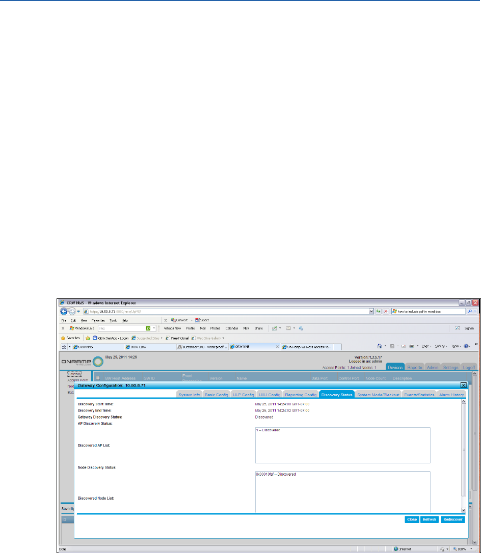
17. Click the Discovery Status tab.
NOTE:
If this is the first time the Gateway has been discovered, the lists and status will be
empty.

ULP EMS Operator Guide Maintaining and Operating the ULP Network
On-Ramp Wireless Confidential and Proprietary 20 010-0045-00
18. Click Rediscover.
NOTE:
A pop-up window asks the operator to confirm the discovery of the Gateway.
Additionally, there is a place to enter an optional note about this configuration
change. All EMS configuration changes are logged to an audit report. The information
here is logged in this report with the configuration change.
19. Click Yes.
20. Click Close.
3.5.3 Enabling the Gateway
To enable the Gateway, complete the following steps:
1. In the Device Selection pane, select Gateway. Then, select the check box next to the
Gateway ID of the Gateway that was just added.
2. Click Enable Event Process.
3. Optional: Type a note in the confirmation box to track this event in the audit report.
4. Click Yes.
3.5.4 Configuring an Access Point
APs are geographically dispersed throughout a wide territory and communicate upstream and
downstream.
Upstream: APs communicate upstream with the Gateway through Transmission Control
Protocol/Internet Protocol (TCP/IP) over various types of physical backhauls. The physical
backhauls are based on the specifics of the network deployment. A typical backhaul might
consist of a leased line and/or microwave.
Downstream: APs provide a wireless coverage footprint for thousands of wireless end-point
devices and/or nodes.
To configure an AP, complete the following steps:
1. Make sure that the operator has the following AP site survey information:
a. IP Address (or DNS resolvable name)
b. Channel Number
c. Reuse Code
2. Log in to the EMS with the admin or configure account.
3. Make sure that a Gateway is enabled.
4. Click the Devices tab.
ULP EMS Operator Guide Maintaining and Operating the ULP Network
On-Ramp Wireless Confidential and Proprietary 21 010-0045-00
5. In the Device selection pane, select Access Point.
NOTE:
If this is the first time adding an AP, this page will be blank. If adding multiple APs,
the APs that were added are displayed in this list.
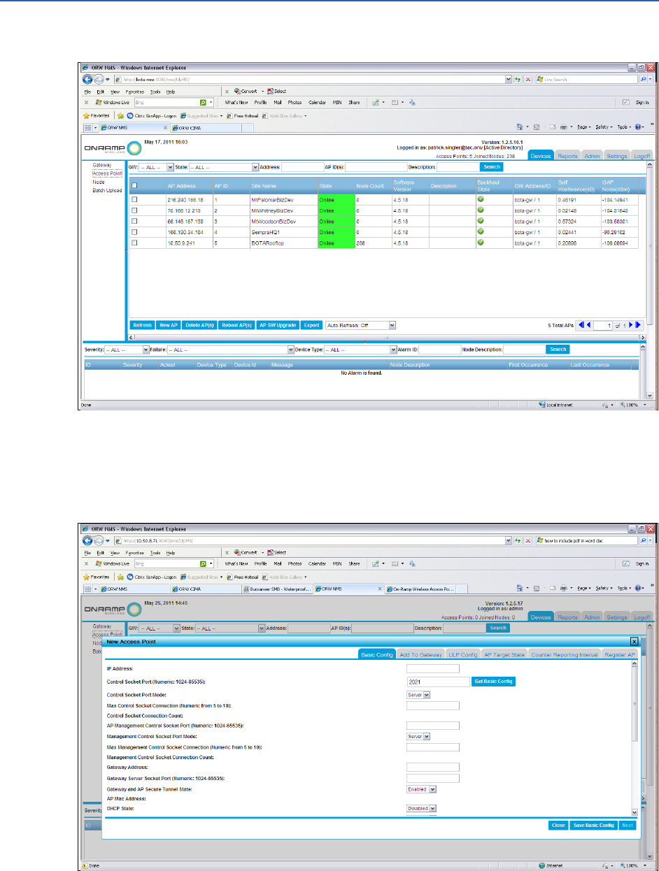
6. Click New AP.
7. In the IP Address field, type the IP address for the AP to be added.

ULP EMS Operator Guide Maintaining and Operating the ULP Network
On-Ramp Wireless Confidential and Proprietary 22 010-0045-00
8. In the Control Socket Port (Numeric: 1024-65535) field, type 2021.
NOTE:
If the operator has different port information from the site survey, the operator
must type a different control socket port number.
9. In the Control Socket Port Mode field, Server is selected from the drop-down list. Do not
change this value.
10. Click Get Basic Config.
NOTE:
This step forces the EMS to obtain the default settings for this AP from the AP itself.
If these values are correct, the operator can use them. If these values are not
correct, the operator can update them in the next steps.
11. Complete the information for the following fields or make changes as appropriate for the
operator's site.
a. In the Max Control Socket Connection (Numeric from 5-10) field, type 5.
b. In the AP Management Control Socket Port (Numeric: 1024-65535) field, type 2022.
NOTE:
If the operator has different port information from the site survey, the operator
must type a different control socket port number.
c. In the Management Control Socket Port Mode field, select Server.
d. In the Max Management Control Socket Connection (Numeric from 5-10) field, type 5.
e. In the Gateway Address field, leave the default value.
f. In the Gateway Server Socket Port (Numeric: 1024-65535) field, type 5051.
g. In the Gateway and AP Secure Tunnel State field, select Enabled from the drop-down
list.
NOTE:
The Disabled option is available for test and development systems or lab systems
only. All production systems use security.
h. In the DHCP State field, select Disabled.
i. In the Telnet State field, select Disabled. This is an additional test system and/or lab
system deployment feature that is not typically enabled in production systems.
j. In the Default Router field, leave the default setting.
k. In the Netmask field, leave the default setting.
l. In the Name Server(s) field, leave the default setting.
m. In the NTP Server(s) field, leave the default setting.
n. Optional: In the AP Site Name (Max 255 characters) field, type a description for this AP.
o. Optional: In the Backhaul Type field, type a description of the type of TCP/IP backhaul
that the AP uses.
p. Optional: In the Country Code(2 letters) field, type a 2 letter country code.
ULP EMS Operator Guide Maintaining and Operating the ULP Network
On-Ramp Wireless Confidential and Proprietary 23 010-0045-00
12. Click Save Basic Config.
NOTE:
If changes were not made, the screen displays no changes made.
If changes were made, a pop-up window allows the operator to enter a description of
this event. This description will be entered into the system's audit report for future
tracking of when changes were made to the system.
13. In the Update Notification pop-up window, click Yes.
NOTE:
If changes were made to the configuration, the AP will reboot. Confirm to reboot the
AP and add an optional audit report log. The operator must wait for the AP to
reboot.
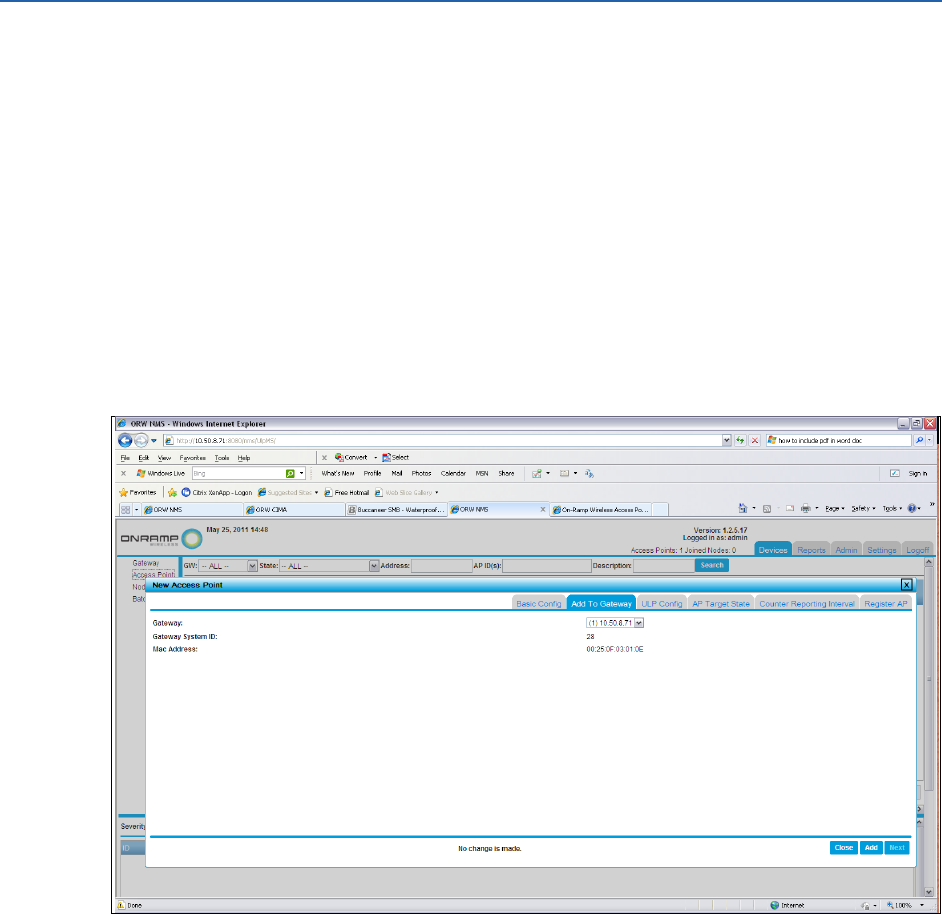
14. Click Next. The Add To Gateway tab is active.
15. Click Add. The pop-up window asks the operator to confirm the addition. A pop-up window
also allows the operator to enter a description of this event. This description will be entered
into the system's audit report for future tracking of when changes were made to the system.
16. Click Yes.
ULP EMS Operator Guide Maintaining and Operating the ULP Network
On-Ramp Wireless Confidential and Proprietary 24 010-0045-00
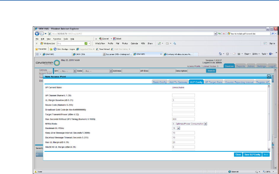
17. Click Next.
18. In the new Access Point window, complete the following field entries using the company
specific site template. If the company template overrides defaults listed below, enter them
when updating these fields.
a. In the AP Channel (Numeric 1-38) field, type the channel of this AP from the site-specific
template.
b. In the UL Margin (Numeric 0-15) field, type 2.
c. In the Reuse Code field, type information from the site-specific template.
d. The Broadcast Gold Code field is grayed out on purpose as this field is auto-generated.
e. In the Target Transmit Power (In dBm 4-32) field, type information from the site-
specific template.
f. In the Max Seconds Without Timing (Numeric: 0-1000) field, type 600.
g. In the RPMA Mode field, enter information from the site-specific template.
h. In the Maximum UL PDUs field, type 16.
i. In the Keep Alive Message Interval (Seconds 5-3600) field, type 10.
j. In the Backhaul Message Timeout (Seconds 5-255) field, type 10.
k. In the Max UL Margin (dB 0-31) field, type 20
l. In the UL Overload Alarm Threshold (dB 0-31) field, type 3.
m. In the AP Interference Alarm Threshold (dB 0-31) field, type 10.
ULP EMS Operator Guide Maintaining and Operating the ULP Network
On-Ramp Wireless Confidential and Proprietary 25 010-0045-00
19. Click Save ULP Config. In the pop-up window, type Yes.
NOTE:
A pop-up window allows the operator to enter a description of this event. This
description will be entered into the system's audit report for future tracking of when
changes were made to the system.
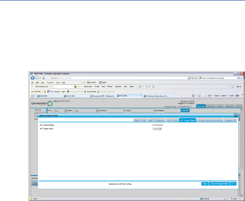
20. Click Next.
21. In the AP Target State window, select Online from the AP Target State drop-down list.
22. Click Save AP Target State. In the pop-up window, click Yes.
NOTE:
A pop-up window allows the operator to enter a description of this event. This
description will be entered into the system's audit report for future tracking of when
changes were made to the system.
ULP EMS Operator Guide Maintaining and Operating the ULP Network
On-Ramp Wireless Confidential and Proprietary 26 010-0045-00
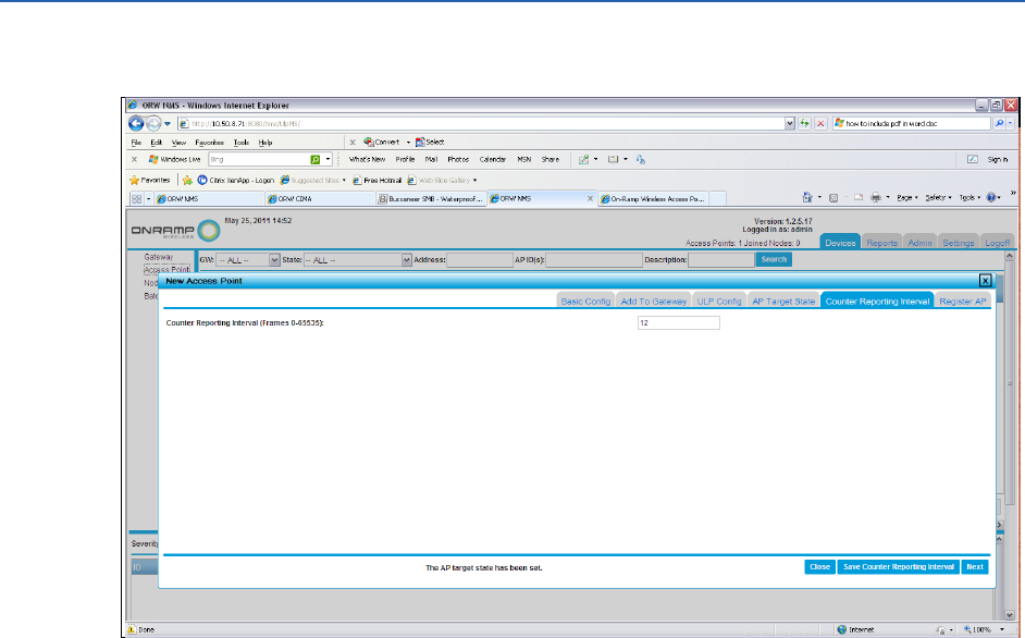
23. Click Next.
24. In the Counter Reporting Interval (Numeric 0-65535) field, type 12.
25. Click Save Counter Reporting Interval.
26. In the Update Notification pop-up window, click Yes.
NOTE:
A pop-up window allows the operator to enter a description of this event. This
description will be entered into the system's audit report for future tracking of when
changes were made to the system.
ULP EMS Operator Guide Maintaining and Operating the ULP Network
On-Ramp Wireless Confidential and Proprietary 27 010-0045-00
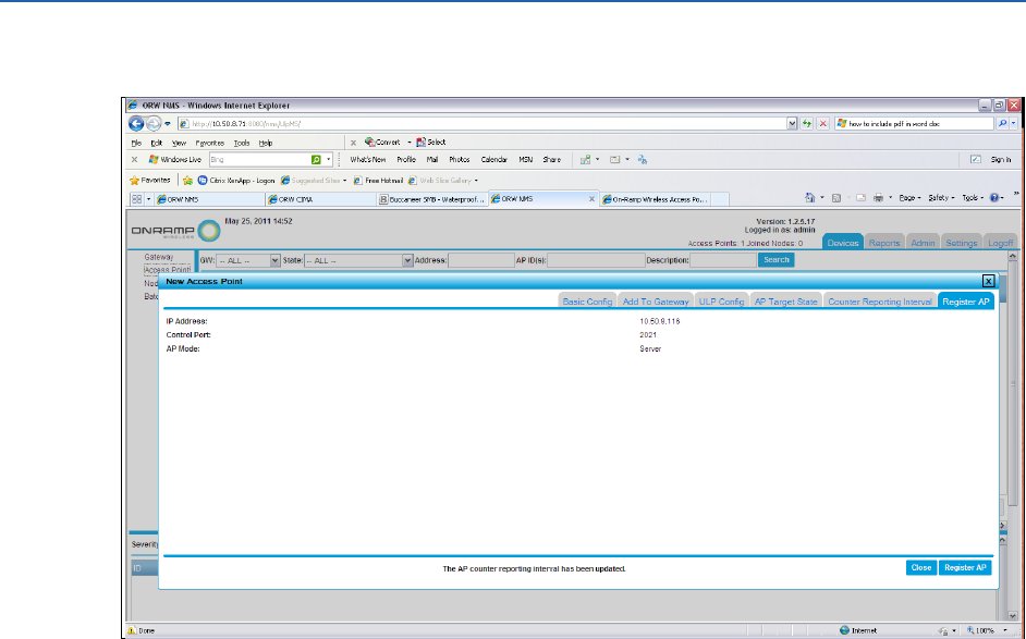
27. Click Next.
28. Click Register AP. A pop-up window asks the operator to confirm the addition.
NOTE:
A pop-up window allows the operator to enter a description of this event. This
description will be entered into the system's audit report for future tracking of when
changes were made to the system.
29. Click Yes.
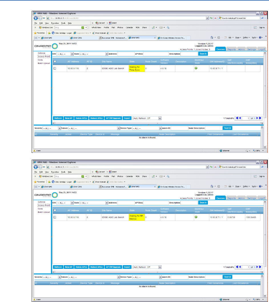
NOTE:
The EMS AP status does not update immediately. Eventually, the status shows that
the AP has transitioned to a yellow state. Alternatively, the operator can click
Refresh from the Access Point Device Listing screen. Depending on when the screen
is refreshed, the operator will see Waiting for Time Sync or Waiting for RF Metrics
display in the State field. This is normal behavior for an AP that is transitioning from
an offline state to an online state. The AP goes through an initialization period in
which it first finds the GPS and then measures the RF noise that the AP experiences.
During this process, the AP adjusts the RF behavior accordingly. Typically, this
adjustment takes approximately 2.5 minutes to complete.
ULP EMS Operator Guide Maintaining and Operating the ULP Network
On-Ramp Wireless Confidential and Proprietary 28 010-0045-00
After the AP adjusts the GPS time sync and RF Metrics, the AP transitions from a yellow
state to a green state as shown below.
ULP EMS Operator Guide Maintaining and Operating the ULP Network
On-Ramp Wireless Confidential and Proprietary 29 010-0045-00
3.5.5 Configuring an End Device
End devices are application specific, and operators may need to configure devices in multiple
ULP network elements. Operators must perform a network configuration to each device from
the EMS. This is called control configuration. Operators must also configure an end device in
CIMA and/or another application-level tool. This is called data configuration.
To perform a network configuration of a device in the EMS, add the device to the EMS to allow it
to join the network, define the type of device (for example, enter the device's intended data
application), and configure the update profile by configuring the Update Interval (UI) and the
Listen Interval (LI).
Adding a remote device is a multi-step process that can last several days in a geographically
diverse network. For example, there may be a work order requesting that several devices of a
particular type, such as an FCI or an RMU, be installed in the upcoming week. The work order
maps specific radio Node IDs (also known as MAC addresses) for each device to be installed to a
device type and the physical location where the device will be installed. When filing the work
order, provide information to the EMS operator. The EMS operator enters specific node
information into the EMS for each device that will be installed. After the EMS is updated, the
operator can install the device. The amount of time between adding a device to the EMS and the
installation of the device in the field can last several days.
The following steps summarize this process:
1. Issue a work order to install devices.
2. Pull the devices from stock, and note the Node ID (MAC address), application (FCI or FAA),
and planned installation location details (district, pole, circuit, etc.).
3. Enter device information from Step 2 (above) into the EMS.
4. Physical device installation is scheduled.
ULP EMS Operator Guide Maintaining and Operating the ULP Network
On-Ramp Wireless Confidential and Proprietary 30 010-0045-00
5. Physical device installation is completed. The devices will connect at this time, and they are
visible in the EMS system.
6. Post installation delivers the completed work order that validates the Node ID (MAC
address), application, and installation location to the CIMA operator for post installation
application data configuration.
3.5.6 Adding an End Device
To add a device, complete the following steps:
1. The operator must have the work order that maps the radio Node ID (MAC address) to the
device type and physical location.
2. Log in to the EMS with an admin or operator account.
3. Make sure a Gateway is established.
4. Make sure an AP is up and running.
NOTE:
Make sure the AP is providing wireless coverage to the physical location of the
device to install.
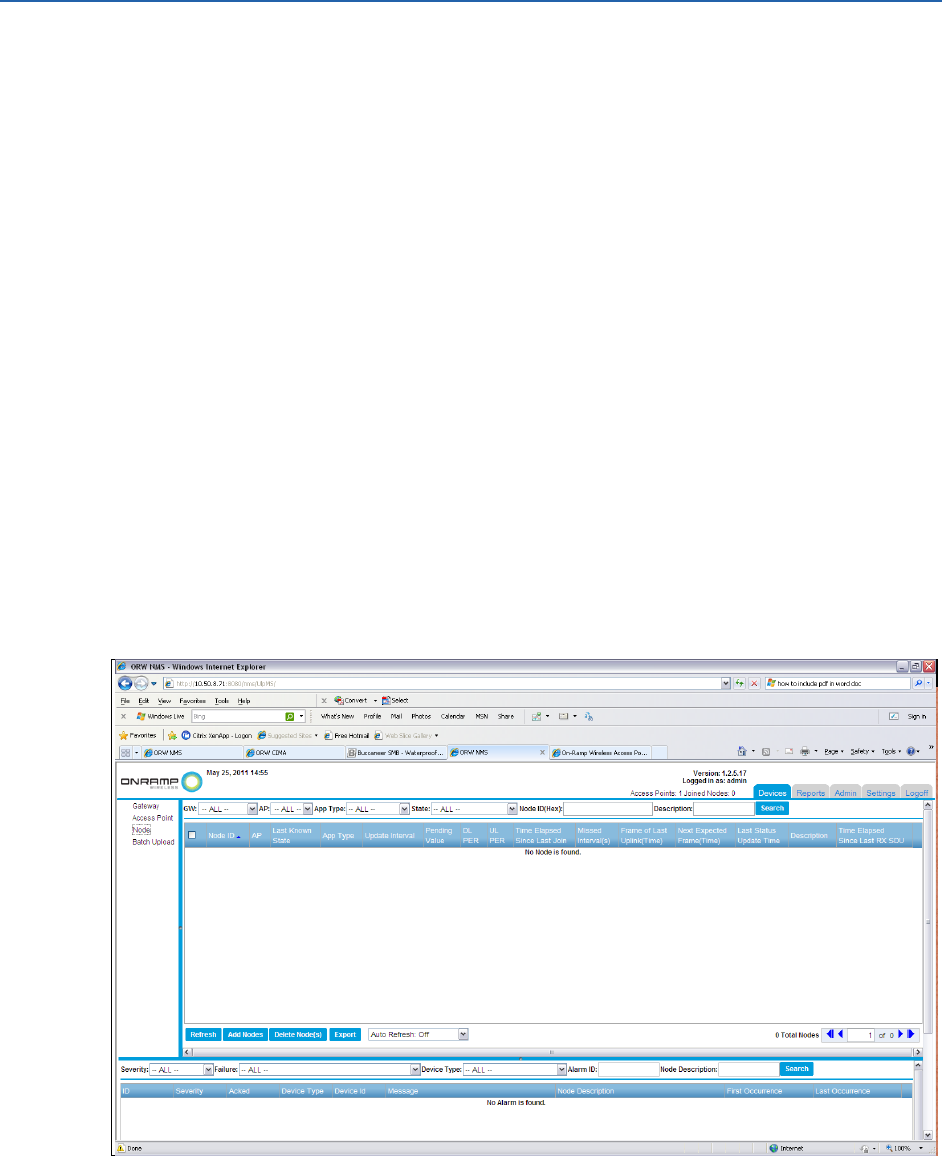
5. Click the Devices tab.
6. In the Devices pane, click Node.
NOTE:
If this is the first time adding an end device, this page will be blank.
ULP EMS Operator Guide Maintaining and Operating the ULP Network
On-Ramp Wireless Confidential and Proprietary 31 010-0045-00
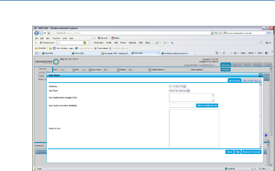
7. Click Add Nodes.
8. Complete the information for the following fields.
a. In the Gateway field, select the Gateway.
b. In the App Type, select the application type for this node from the drop-down list.
c. Optional: Enter a description for the node.
d. In the Add Node ID (In HEX: 0x0000) field, type the ID of the radio node.
9. Click Move to Node ID List. The node displays in the Node ID List field.
10. Click Add.
11. Click Add. A message displays stating that the Node is being added. After the node is
added, it will report Nodes are added.
12. Repeat Steps 8.b through 9 for as many nodes as needed to add for this work order.
3.5.7 Configuring a Specific Device Update Interval (UI) or Listen
Interval (LI)
It is critical that the operator set the device UI and/or LI correctly.
ATTENTION:
The UI/LI for a given device controls how often a device wakes up to receive or
transmit data. This configuration directly controls the energy that a given device
uses. For battery-powered devices, these settings impact how long the battery for
a battery powered device lasts. The tables below define the UI/LI for each type of
device. The operator must follow the settings in this document unless directed
otherwise by the appropriate On-Ramp Wireless personnel.
ULP EMS Operator Guide Maintaining and Operating the ULP Network
On-Ramp Wireless Confidential and Proprietary 32 010-0045-00
To configure a specific device Update Interval (UI) or Listen Interval (LI), complete the following
steps:
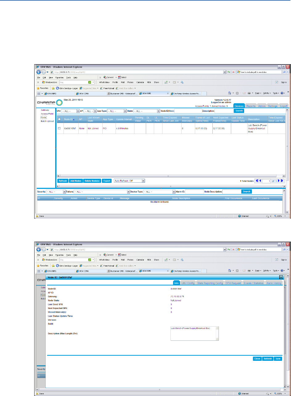
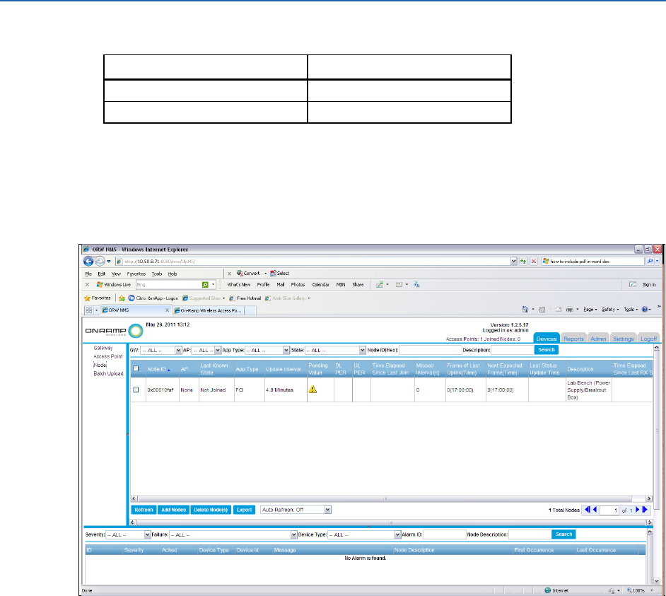
1. In the Device Selection Pane, click on Node. From the Node Device Listing Pane, select the
Node ID of the node to configure. For example, in the following screen, there is one node in
the list of nodes. This node has a Node ID of 0x10faf.
2. Click the Node.
ULP EMS Operator Guide Maintaining and Operating the ULP Network
On-Ramp Wireless Confidential and Proprietary 33 010-0045-00
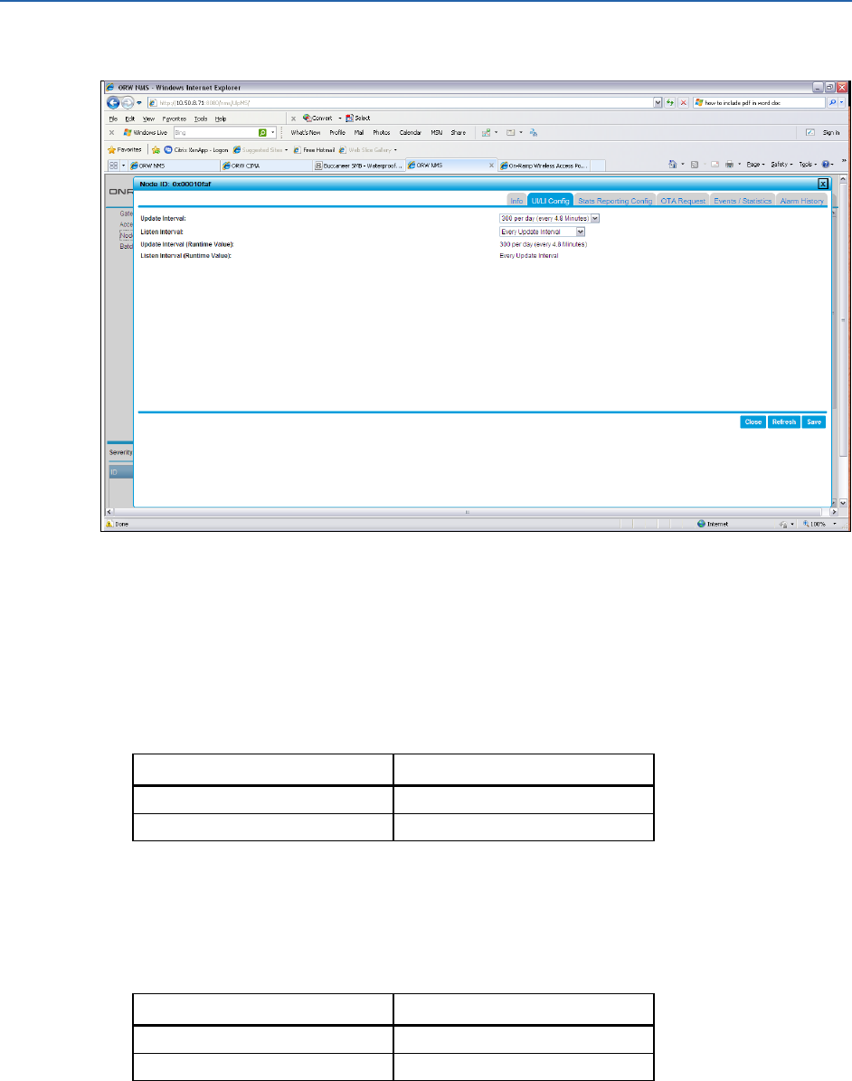
3. Click the UI/LI Config tab.
This release of the ULP EMS Operator Guide includes the following supported types of end
devices (nodes):
Sysmon: System monitor node that provides network-specific information to the EMS
operator. This helps the EMS operator to understand the health of the ULP network.
Configure the UI and LI with the values from the following table.
Table 1. Sysmon UI and LI Values
Interval (UI and LI)
Value
UI
every frame
LI
Every update interval
Fault Circuit Indicator (FCI): Battery powered distribution line device that reports
current and/or voltage faults in a distribution line.
Configure the UI and LI with the values from the following table.
Table 2. FCI UI and LI Values
Interval (UI and LI)
Value
UI
1 per day (24 Hours)
LI
Every update interval
Remote Monitoring Unit (RMU): Monitors the obstruction lights and reports the
outages of the obstruction lights. These outages must be reported to the FAA.
Configure the UI and LI with the values from the following table.
ULP EMS Operator Guide Maintaining and Operating the ULP Network
On-Ramp Wireless Confidential and Proprietary 34 010-0045-00
Table 3. RMU UI and LI Values
Interval (UI and LI)
Value
UI
60 per day (24 minutes)
LI
Every update interval
4. After entering the UI and LI for a device, click Save, and click Yes. The device that was just
added displays on the list as Not Joined with an asterisk in the Pending Value field. This
denotes that the device has been configured in the EMS, but it has not yet joined the
network. The device will stay in this state until it is physically deployed, powered on, and
joins the network.
NOTE:
Sysmon nodes show a critical alarm after they have been added to the EMS, prior to
being powered on. Ignore this alarm. After the Sysmon nodes are powered on, this
alarm will be automatically cleared.
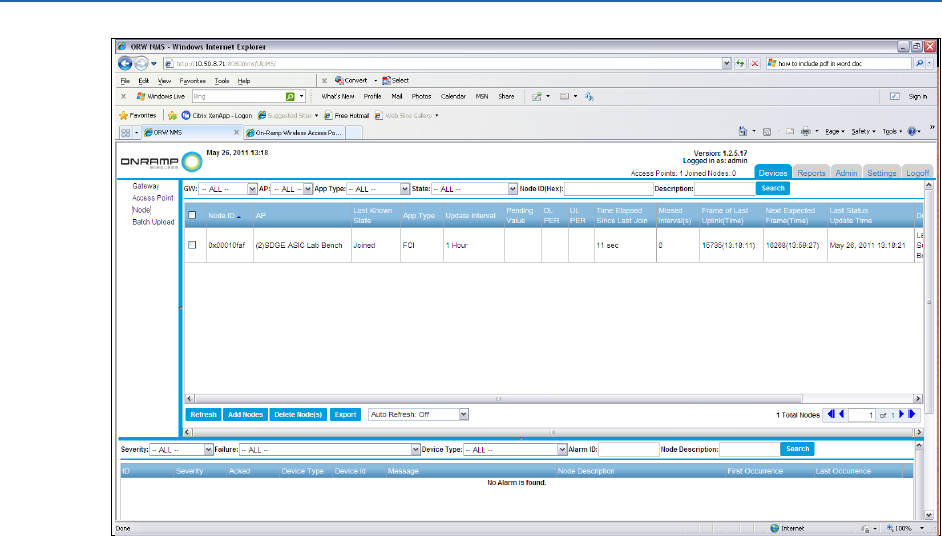
5. Optional: To confirm that the correct UI/LI for the device was set, select the device from the
list of devices, and click the UI/LI Config tab. Verify the configuration information.
After verifying the configuration information, the node has been added to the EMS. The
work order proceeds with the physical installation of the device. After the devices are
powered on in the field, the EMS operator can confirm (in the EMS) that these devices have
joined the network. The operator can easily identify which device has joined the network, as
the Pending Value asterisk is not displayed.
ULP EMS Operator Guide Maintaining and Operating the ULP Network
On-Ramp Wireless Confidential and Proprietary 35 010-0045-00
3.6 Day to Day Operations
An EMS operator performs several tasks during the initial deployment of the network and
adding end devices to the ULP network. For day to day operations of the ULP network, the EMS
operator does not need to use the EMS console directly.
In a typical ULP network deployment, the system can operate for months without ever
generating an EMS alarm event. For day to day operations, the EMS supports email alerts to
automatically notify operators of EMS alarms.
When the EMS generates an alarm email, the EMS operator uses the EMS console to
acknowledge the alarm and debug the reason for a given ULP alarm. Typically, the operator
might use a combination of console monitoring and email alerts to operate the system daily.
If the EMS operator uses the EMS console daily to maintain the ULP network, it is recommended
that they set up and use the email notification alarm system to help identify issues with the ULP
network. In general, the EMS console displays system-wide alarms without requiring additional
configuration.
The EMS contains alarm functionality to help diagnose issues at all levels of the network. The
EMS will generate alarms for issues with:
Gateways
Access Points
End Devices (Nodes)

ULP EMS Operator Guide Maintaining and Operating the ULP Network
On-Ramp Wireless Confidential and Proprietary 36 010-0045-00
3.6.1 Summary of Alarms
This section summarizes EMS generated alarms. The following table contains a short summary
for each alarm, including:
1. Network element affected by the alarm
2. Severity of the alarm
3. Short description of the alarm
4. Alarm clearing condition
The sub-sections, after the table, provide details for each alarm, such as descriptions for each
alarm and how to proceed when receiving each type of alarm.
Table 4. Alarm Type and Severity, Description, and Clearing Condition
ULP Network
Element
Severity
Description
Clearing Condition
GW Process
Health
Critical
An GW to EMS
connectivity timeout.
Re-establishing GW to EMS backhaul port
connectivity.
AP Process
Health
Critical
An AP or AP/GW
backhaul error.
Re-establish the AP process and/or
AP/GW Backhaul Connectivity.
AP Not Online
Critical
An AP is offline
AP goes back online
PPM Drift
Critical
An AP crystal drifted out
of tolerance.
Automatically cleared when the AP crystal
is back in tolerance.
Overload
Adjustment
Critical
The AP has determined
that the node capacity is
overloaded.
Automatically cleared when the AP over
load condition has been cleared.
Software Asserts
Info
A ULP Gateway, an AP,
or a Node has generated
a software assert.
Automatically cleared by the software.
Node Frequent
Rejoin
Major
An end device has
rejoined the network >
10 times in a 250 second
window.
Automatically cleared when a node does
not rejoin > 10 times in a 250 second
window.
Node Missed
Intervals
Minor,
Major,
Critical
A Node has missed
update intervals.
Automatically cleared when a node stops
missing update intervals.
Sysmon Node
Communications
Critical
A Sysmon end device
has not communicated to
an AP in its expected
interval.
Automatically cleared when the Sysmon
rejoins the AP and starts communicating.
Frame Squishing
Critical
EMS DB
Backlog
Major
The EMS database is
falling behind.
Automatically cleared when the database
catches up.
Interference
Critical
Automatically cleared when the
interference clears up.
ULP EMS Operator Guide Maintaining and Operating the ULP Network
On-Ramp Wireless Confidential and Proprietary 37 010-0045-00
Node Join
Failure
Major
An alarm generated
when an end device is
not allowed to join the
network by the GW.
Automatically cleared when the underlying
cause is fixed and the device is allowed to
join the network. This is cleared if the
device is deleted from the EMS, because it
was not supposed to be allowed onto the
network.
TX Suppression
Critical
Automatically cleared.
AP Proximity
Fault
Warning
An AP lid has been
opened.
Cleared when the AP lid is closed.
AP GPS Fault
Warning
An AP has lost its GPS
fix.
Cleared when the AP can get a GPS fix.
AP VC-TCXO
High
Temperature
Warning
The AP operating
temperature is too high.
Cleared automatically when the AP
temperature is brought down.
AP PA High
Temperature
Warning
The AP operating
temperature is too high.
Cleared automatically when the AP
temperature is brought down.
AP Max VGA
Exceeded
Warning
Automatically cleared.
AP Min VGA
Exceeded
Warning
Automatically cleared.
AP Fragmented
Channel
Threshold
Exceeded
Warning
Automatically cleared.
Message
Processing
Delay
Major
The EMS database is
taking too long to insert
raw messages into rows.
EMS database processing returns to
normal operation.
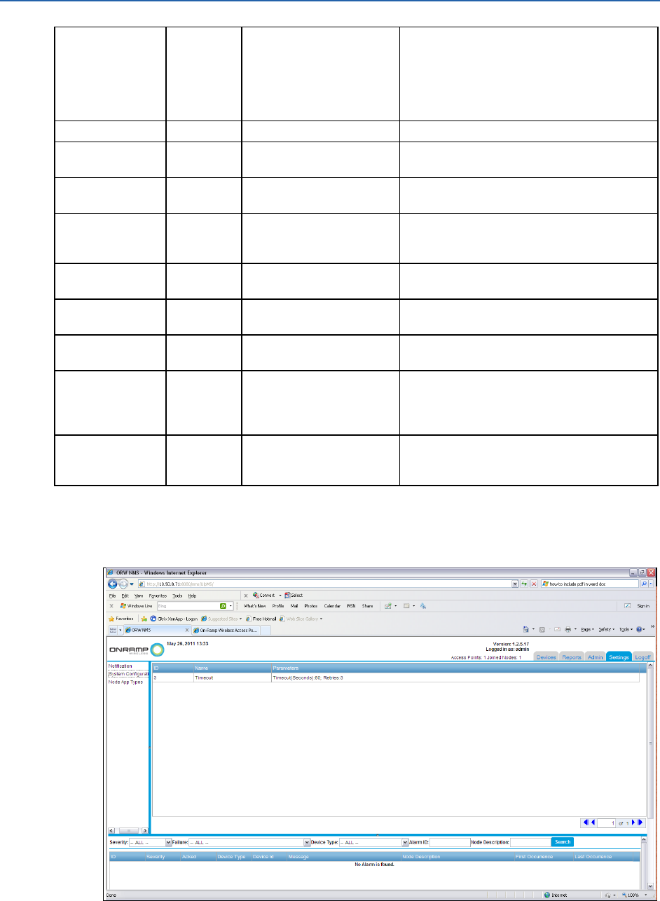
The following items are various EMS configurations that affect alarm operation:
1. The Keep Alive configuration of the GW controls the GW Health Alarm. To confirm the
timeout settings for the alarm, navigate to the screen shown below.

ULP EMS Operator Guide Maintaining and Operating the ULP Network
On-Ramp Wireless Confidential and Proprietary 38 010-0045-00
2. A system administrator can control additional default parameters for the following
alarms through editing the /opt/onramp_apps/nms_config.properties file on the EMS
server. If editing the nms_config.properties file after starting the EMS, restart the EMS
backhaul to show the changes. Some alarms can be permanently disabled by setting
parameters in the nms_config.properties file. For detailed information about
permanently disabling alarms, call On-Ramp Wireless.
a. The following alarms have configuration parameters in the nms_config.properties
file:
GW Health Alarm Timeout
Node Missed Intervals
Node Frequent Rejoins
Sysmon Node Communications
b. To restart the EMS backhaul, the system administrator should log in to the EMS
server through a terminal and run:
/sbin/service onramp_EMS_backhaul stop
/sbin/service onramp_EMS_backhaul start
3.6.1.1 GW Process Health
This type of alarm indicates that the EMS and Gateway (GW) cannot maintain communication
through the network backhaul. The following conditions can cause a connectivity alarm:
1. The GW server and/or software process has died. To verify that the GW server and software
are running, complete these steps:
a. Log on to the physical GW server using a UNIX®/Linux® terminal shell. If the operator
cannot log in to the GW, they may need to verify the physical status of the GW.
b. Run the following command from the shell prompt:
/sbin/service ulp-gateway status
The output from this indicates if the GW is running.
c. Restart the GW with the following commands from the shell prompt:
/sbin/service ulp-gateway stop
/sbin/service ulp-gateway start
2. The network connectivity between the EMS and the GW is broken. An operator should use
the standard networking debugging tools to verify the availability of the backhaul
connectivity between the EMS and the GW. For example, the operator can ping the GW to
validate that it is available through the backhaul network. When re-establishing the
backhaul connectivity, the operator may need to contact the backhaul provider to help
diagnose the issue.

ULP EMS Operator Guide Maintaining and Operating the ULP Network
On-Ramp Wireless Confidential and Proprietary 39 010-0045-00
3.6.1.2 AP Process Health
This type of alarm indicates that the AP and GW cannot communicate. This is due to the
following reasons:
1. The AP died. To diagnose the AP, complete these steps:
a. Log in to the AP web page:
https://<AP IP address>
b. From the AP web page, note the status of the AP.
c. From the EMS and/or AP web page, reboot Access Point.
2. The network connectivity between the AP and GW is broken. An operator should use
standard networking debugging tools to verify the availability of the backhaul connectivity
between the AP and GW. For example, the operator can ping the AP to validate that it is
available through the backhaul network. When re-establishing the backhaul connectivity,
the operator may need to contact the backhaul provider to help diagnose the issue.
3.6.1.3 AP Not Online
This type of alarm indicates that the AP is in an offline state due to an unplanned event.
NOTE:
This is not due to a backhaul outage, and the operator should not have to diagnose the
network connectivity.
This alarm can be investigated in the following ways:
1. From the EMS:
a. In the Devices->Access Point pane of any EMS screen, select the alarming AP. Explore
the state of the AP through the detailed AP listings.
b. After diagnosing the AP, the operator may need to reboot the AP from the EMS AP
detailed pages console.
2. From the AP web page:
NOTE:
In some cases, the EMS may not provide sufficient ways in which to diagnose the
problem.
a. Log in to the AP web page:
https://<AP IP address>
b. From the AP web page, determine the status of the AP.
The operator may need to reboot Access Point from the AP web page.
3.6.1.4 PPM Drift
NOTE:
The PPM drift alarm is a serious alarm that is not likely to be cleared without a service
call to On-Ramp Wireless. If this alarm has been detected, or if this alarm has been
cleared, call On-Ramp Wireless.

ULP EMS Operator Guide Maintaining and Operating the ULP Network
On-Ramp Wireless Confidential and Proprietary 40 010-0045-00
The operator can attempt to clear the alarm by rebooting the AP generating this alarm. If this
clears the alarm, call On-Ramp Wireless.
If rebooting the AP does not clear the alarm, move the AP to an offline state in the EMS, and call
On-Ramp Wireless.
3.6.1.5 Overload Adjustment
The overload adjustment alarm is not likely to be cleared without a service call to On-Ramp
Wireless. If this alarm is detected, call On-Ramp Wireless. On-Ramp Wireless may schedule a
service call to perform an AP forced rescan to fix this issue.
3.6.1.6 Software Asserts
The On-Ramp Wireless AP, GW, and Node software automatically detects various error
conditions. When an error is detected, the software may generate an assert alarm.
The assert alarm generates a log message with a reason code, including a line of code and the
file responsible for the alarm. If there is an AP, GW, or Node assert alarm, it is typically expected
that the assert will result in an automatic restart of the GW, AP, or Node that generated the
assert condition.
In the event of an assert alarm, the following situations may exist:
1. The underlying cause of the software alert is due to an unforeseen system issue, such as an
assert that is being generated repeatedly. This indicates that there is a system failure, and
the operator must call On-Ramp Wireless.
2. The underlying cause of the software alert is due to an unforeseen event that happens very
infrequently. This assert is not likely to be seen again, and the system is again operating as
expected. Notify On-Ramp Wireless of this assert alarm.
3.6.1.7 Node Frequent Rejoin
If an end device is frequently rejoining, it can indicate an error in many different aspects of the
system.
The operator should schedule a service call. The appropriate On-Ramp Wireless personnel may
come on site to get additional information from the EMS system. The On-Ramp Wireless
personnel may also direct an EMS operator to enable additional debugging aspects of the device
through the EMS console.
To clear the problem, try to reboot the GW and/or AP. This may not resolve the problem.
3.6.1.8 Node Missed Intervals
This alarm indicates that an end device missed a configurable number of scheduled update
intervals.
The system uses the following defaults for missed intervals:
Three missed intervals trigger a minor alarm.

ULP EMS Operator Guide Maintaining and Operating the ULP Network
On-Ramp Wireless Confidential and Proprietary 41 010-0045-00
Four missed intervals trigger a major alarm.
Five missed intervals trigger a critical alarm.
NOTE:
To guarantee that EMS operators receive RMU network alarms before CIMA
operator alarms, modify the alarms to be 1, 2, and 3 instead of 3, 4, and 5. Using
these settings will enforce that EMS operators must clear network issues before
they propagate to CIMA operators. This configuration guarantees that the NMS
operators will be the first responders to system events and have time to debug/clear
up any ULP issues prior to the alarm elevating to the application operator level.
The RMU obstruction light update interval is 24 minutes. With settings of 1, 2, and 3 as
discussed above, these alarms would correspond to a RMU that is missing 24, 48, or 72 minutes
of updates respectively.
The update interval for FCIs is one per day. With settings of 1, 2, and 3, these alarms would
correspond to an FCI that is missing 1, 2, or 3 days of daily updates.
If an end device reports missed update interval alarms, it may be a network or device specific
issue.
While debugging this issue, contact the CIMA operator and inform them that there are end
devices alarming on the network side. If an end device is missing EMS update intervals, it may be
flagged in the CIMA system if the application CIMA missed interval alarm is configured as having
the EMS and CIMA alarm intervals overlap.
If the EMS alarm is based on a single end device, and the CIMA operator confirms a CIMA alarm,
the CIMA operator should confirm missed update intervals and provide other information that
can explain the outage. For example, the FCI reporting this error may need a battery
replacement, or the RMU reporting this event may have an issue with its battery charging
system. If the problem cannot easily be described as a known issue with an FCI or RMU, the
problem may be network related. The operator should schedule a service call. The appropriate
On-Ramp Wireless personnel may come on site to get additional information from the EMS
system. The On-Ramp Wireless personnel may also direct an EMS operator to enable additional
debugging aspects of the device through the EMS console.
To clear the problem, reboot the GW and/or AP. This may or may not solve the immediate issue.
3.6.1.9 Sysmon Node Communications
The Sysmon is a dedicated end device that monitors an AP in the ULP network. Typically, there is
one Sysmon per AP.
If a Sysmon alarm occurs, it is most likely due to a ULP network issue. The operator should
schedule a service call. The appropriate On-Ramp Wireless personnel may come on site to get
additional information from the EMS system. The On-Ramp Wireless personnel may also direct
an EMS operator to enable additional debugging aspects of the device through the EMS console.
To clear the problem, reboot the GW and/or AP. This may not solve the issue.

ULP EMS Operator Guide Maintaining and Operating the ULP Network
On-Ramp Wireless Confidential and Proprietary 42 010-0045-00
3.6.1.10 Frame Squishing
The frame squishing alarm is not likely to be cleared without a service call to On-Ramp Wireless.
If this alarm is detected, call On-Ramp Wireless.
3.6.1.11 EMS DB Backlog
This alarm is set when the time difference between the EMS last queued raw message and the
last inserted messages grow larger than some configured value (default 5 minutes). This alarm
typically will require DBA related actions, such as purging or partitioning database tables.
If the DBA cannot clear the alarm, schedule an On-Ramp Wireless service call.
3.6.1.12 Interference
The interference alarm is not likely to be cleared without a service call to On-Ramp Wireless. If
this alarm is detected, call On-Ramp Wireless.
3.6.1.13 Node Join Failure
This alarm would typically be generated if an end device was trying to join the network, but it
was not previously provisioned and added to the EMS. To fix the problem, add the node through
the EMS, and configure the UI according to the procedures in this document.
If the device has been added to the network, there may be a security key mismatch. See the
KMS documentation, and make sure that security keys have been imported. Additionally, the
operator may need to debug the KMS, EMS, and GW IP connectivity to make sure there are no
issues with the TCP/IP connectivity between these elements.
If the problem persists, call On-Ramp Wireless.
3.6.1.14 TX Suppression
The TX Suppression alarm is not likely to be cleared without a service call to On-Ramp Wireless.
If this alarm is detected, call On-Ramp Wireless.
3.6.1.15 AP Proximity Fault
This alarm is generated by an AP lid being opened. The opening of the AP's lid may be planned
or unplanned. In a planned opening of the AP’s lid, the alarm will be cleared when the service
call is completed. If the operator receives an AP open lid alarm for an unplanned AP service call,
an unauthorized person may be opening the AP’s lid. Appropriate action, per internal policies,
should be taken.
3.6.1.16 AP GPS Fault
This alarm is the result of an AP that loses its ability to get a valid GPS tracking signal. This is
most likely due to a physical problem with either the AP and/or GPS antenna connected to the
AP. This type of alarm would likely be in conjunction with other alarms (for example AP offline)

ULP EMS Operator Guide Maintaining and Operating the ULP Network
On-Ramp Wireless Confidential and Proprietary 43 010-0045-00
as an AP cannot operate without a GPS fix. The operator may need to roll a service truck to
establish whether there is any issue with the antenna connectivity of the GPS antenna to the AP.
3.6.1.17 AP VC-TCXO High Temperature
This alarm is the result of the AP operating in a temperature extreme that is above its intended
design target. The operator should investigate the AP's physical location, and validate that it is
operating within its installed operating parameters. If the physical operating environment for
the AP is within its operating parameters, the operator should call On-Ramp Wireless.
3.6.1.18 AP PA High Temperature
This alarm is the result of the AP operating in a temperature extreme that is above its intended
design target. The operator should investigate the AP's physical location, and validate that it is
operating within its installed operating parameters. If the physical operating environment for
the AP is within its operating parameters, the operator should call On-Ramp Wireless.
3.6.1.19 AP Max VGA Exceeded
This alarm is not likely to be cleared without a service call to On-Ramp Wireless. If this alarm is
detected, call On-Ramp Wireless.
3.6.1.20 AP Min VGA Exceeded
This alarm is not likely to be cleared without a service call to On-Ramp Wireless. If this alarm is
detected, call On-Ramp Wireless.
3.6.1.21 AP Fragmented Channel Threshold Exceeded
This alarm is not likely to be cleared without a service call to On-Ramp Wireless. If this alarm is
detected, call On-Ramp Wireless.
3.6.1.22 Message Processing Delay
If this alarm occurs, the time difference between the last queued database raw message and the
last inserted database message has grown longer than the default (default is 5 minutes). This
means that database actions are falling behind and may require a DBA to take database action.
For example, the DBA may need to perform database related actions, such as purging or
partitioning. Call On-Ramp Wireless for help in analyzing this type of alarm.
3.6.2 Configuring Alarm Emails
Configure the EMS alarm notification system before using it.
To configure the EMS notification alarm system, log in as a user with admin privileges.
NOTE:
The EMS email configuration in the /opt/onramp_apps/nms_config.properties file must
be configured according to the directions in the EMS Installation Guide.
ULP EMS Operator Guide Maintaining and Operating the ULP Network
On-Ramp Wireless Confidential and Proprietary 44 010-0045-00
To configure email based alarms, complete the following steps:
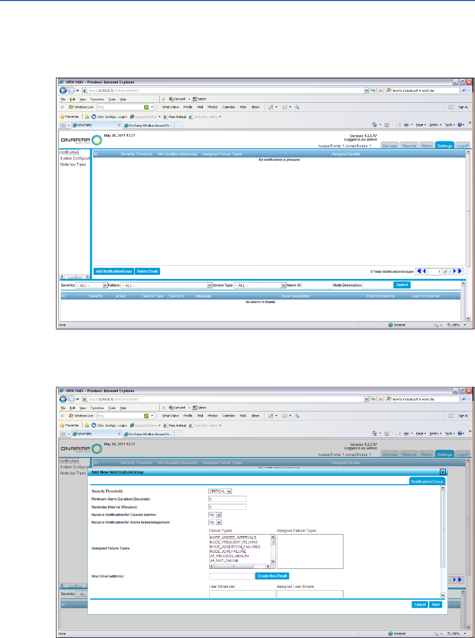
1. Log in to the EMS console, and click the Settings tab. If this is the first time creating email
based alarms, the screen will be blank as shown in the following figure.
2. In the left pane, click Notification.
3. Click Add Notification Group.

ULP EMS Operator Guide Maintaining and Operating the ULP Network
On-Ramp Wireless Confidential and Proprietary 45 010-0045-00
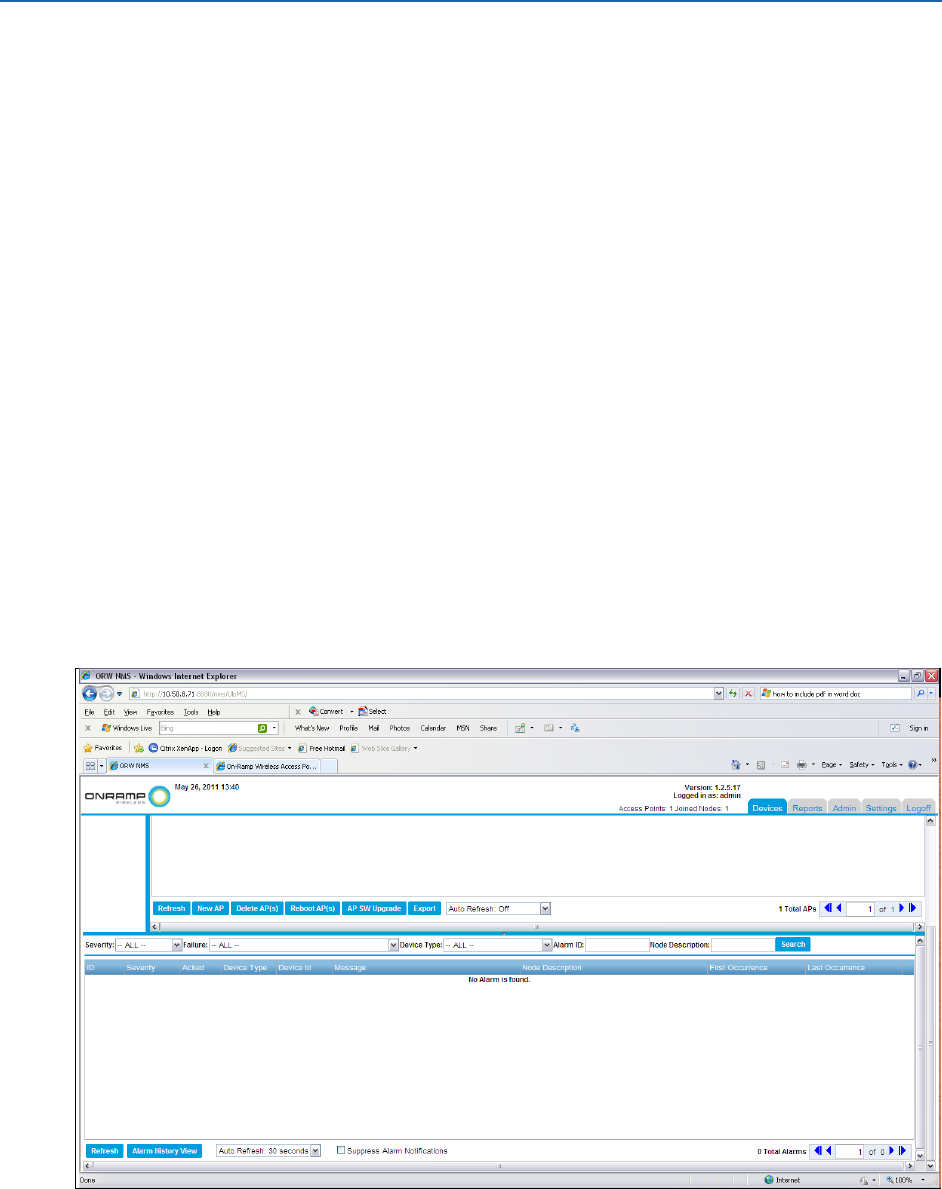
4. In the new Add New Notification Group window, complete the information for the
following fields.
a. In the Severity Threshold field, select the alarm severity for this email notification group
from the drop-down list.
NOTE:
Depending on the threshold for a chosen alarm severity, an email is generated for
alarms at that level or above that level in importance. For example, when
choosing Major Alarms, an email for Major or Critical is generated. The following
importance levels for alarms range in order from highest importance to least
importance:
Critical
Major
Minor
Warning
Info
b. In the Minimum Alarm Duration (Seconds) field, type the duration of time in which an
email alert will be triggered. For example, if this parameter is set to 10 seconds, and the
operator receives an alarm that is self-cleared in less than 10 seconds, the email alert
will not be generated. If the operator wants an email for every alarm regardless of the
interval, the operator should set this parameter to 0.
c. In the Reminder Interval (Minutes) field, type the number of minutes between alarm
reminder emails. This parameter generates a reminder alert email until the alarm is
acknowledged. If the operator does not want to receive reminder emails, the operator
should set this parameter to 0.
NOTE:
Be careful with the value set in this field. If setting a short reminder threshold,
several system emails for unacknowledged alarms can be generated. For
example, if setting a 1 minute threshold and it takes an operator an hour to
acknowledge an alarm, 60 reminder emails based on the 1 minute setting can be
generated. Typically, the operator can set 1-2 hours for the reminder email.
d. In the Receive E-mail for Cleared Alarms field, select Yes or No from the drop-down list.
e. In the Receive E-mail for Acknowledgment field, select Yes or No from the drop-down
list.
f. In the Assigned Failure Types fields, drag the alarms to configure for this notification
group from Failure Types to Assigned Failure Types.
ULP EMS Operator Guide Maintaining and Operating the ULP Network
On-Ramp Wireless Confidential and Proprietary 46 010-0045-00
NOTE:
Several email alert notification groups can be created as necessary for work flow.
In this field, the operator can segment alarm types and create email groups that
are alerted for issues that are of concern. For example, node side alarms should
automatically facilitate the EMS operator to contact the CIMA operator to clarify
the operation of the end device. In this case, it may be beneficial to create an
alarm notification group that selects the node alarm failure types to be sent to a
CIMA email group. The CIMA operators will automatically receive an email alert
from the EMS alarm system when there is a node alarm that they should pay
attention to.
g. In the New E-Mail Address field, type the email addresses for the notification group. If
this is the first time creating notification groups, type the email addresses in this field.
When adding emails in this field, click Create New E-mail. This adds the email addresses
to the User E-mail List.
h. In the Assigned User E-mails field, drag the user's email address from the User E-mail
List to Assigned User E-mails to create the email list for this notification group.
i. Click Save.
Appendix A contains an example of an email alert message. When configuring and using the
email alarm notification system, the operator can disable the email alarms. To disable email
alarms, the operator must log in to the EMS console, and select the Suppress Alarm Notification
E-mails box in the Alarms Summary pane. The Alarms Summary pane is shown below.
3.6.3 Details of the Alarm Console
EMS alarms are visible in the EMS operator’s console display. On the EMS login screen, the
lower pane displays the active alarms in the EMS.
ULP EMS Operator Guide Maintaining and Operating the ULP Network
On-Ramp Wireless Confidential and Proprietary 47 010-0045-00
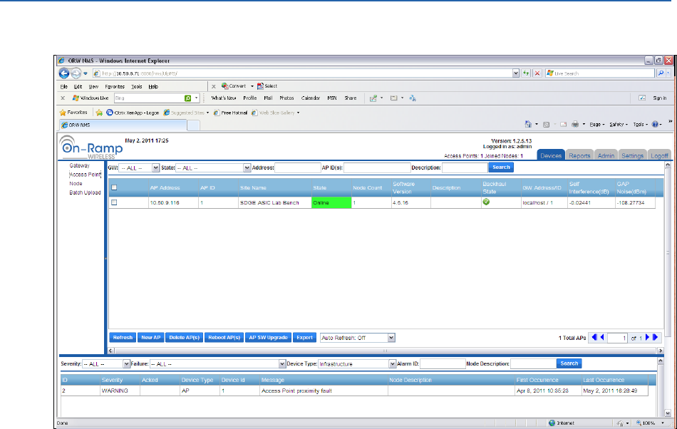
In the following example, there is a single warning in the system.
The single warning is an AP proximity alarm meaning that the lid of AP ID #1 has been opened. If
the email alarm system is in use, this alarm contains an email alert message. For more
information, see Appendix A.
As shown in this example screenshot, the alarm pane of the EMS display includes several drop-
down lists and search fields to help sort and quickly find alarms if there are many alarms to sort
through.
The Severity drop-down list allows operators to clear the alarm pane of all alarms except for
alarms of a selected severity.
The Failure drop-down list allows operators to clear the alarm pane of all alarms except for
alarms of a given failure type.
The Device Type drop-down list allows operators to clear the alarm pane of all alarms
except for alarms of a given device.
The Alarm ID search field allows operators to search for an Alarm ID from an email. Each
alarm email includes an alarm ID. Use this search field to quickly find known alarms. This
facilitates quick searches to be able to acknowledge alarm emails.
The Node Description search field allows operators to perform partial matches on
information for each node's description field.
When an alarm has been generated, the EMS operator should acknowledge the alarm before
debugging the issue, particularly if email reminders have been enabled as described above in
Configuring Alarm Emails.
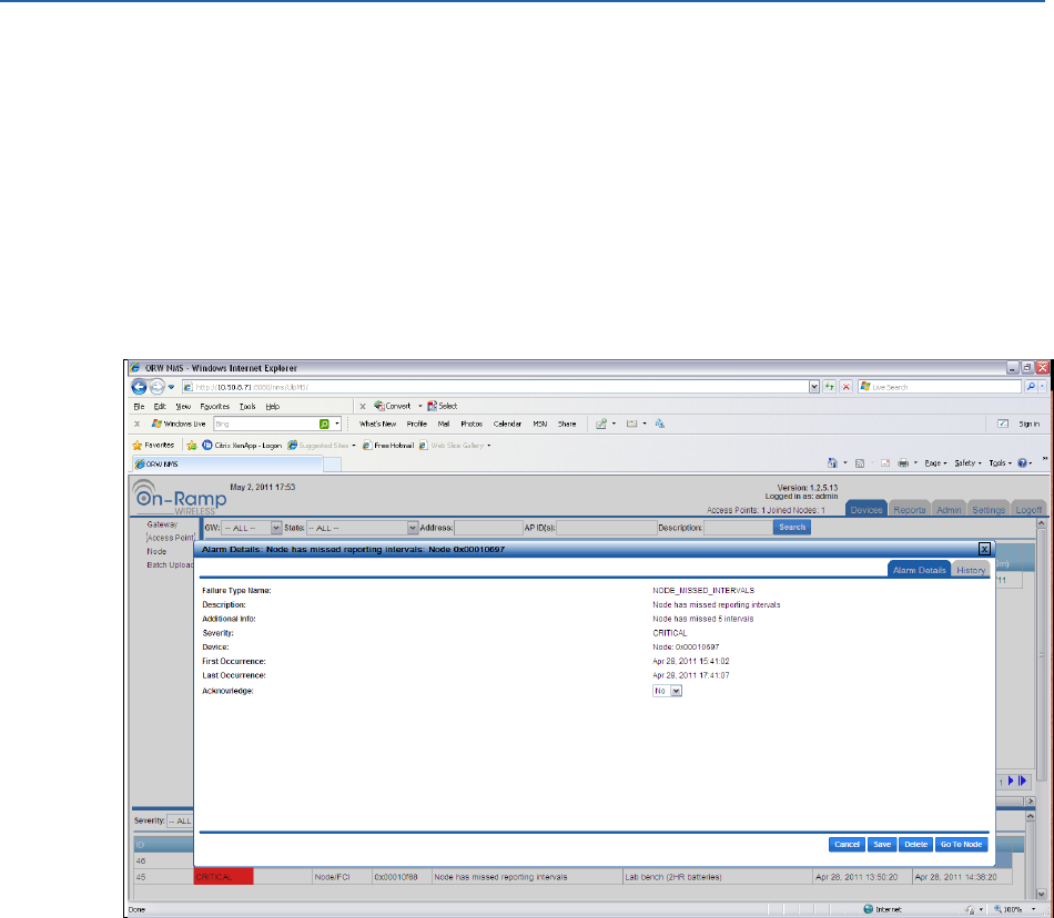
ULP EMS Operator Guide Maintaining and Operating the ULP Network
On-Ramp Wireless Confidential and Proprietary 48 010-0045-00
3.6.4 Acknowledging Alarms
Alarms only need to be acknowledged if the operator previously enabled the EMS to continue to
send email alerts for non-acknowledged alarms. If the operator configured the EMS email
system to send reminder emails, the system will continue to send email reminders for non-
acknowledged alarms at the interval rate specified. Once an alarm has been acknowledged,
reminder emails will not be sent for the acknowledged alarm.
To acknowledge an alarm, complete the following steps:
1. In the alarm pane, select the active alarm.
2. In the Alarm Details window, select Yes from the Acknowledge drop-down list.
3. Click Save. The pop-up window asks the operator to acknowledge the alarm.
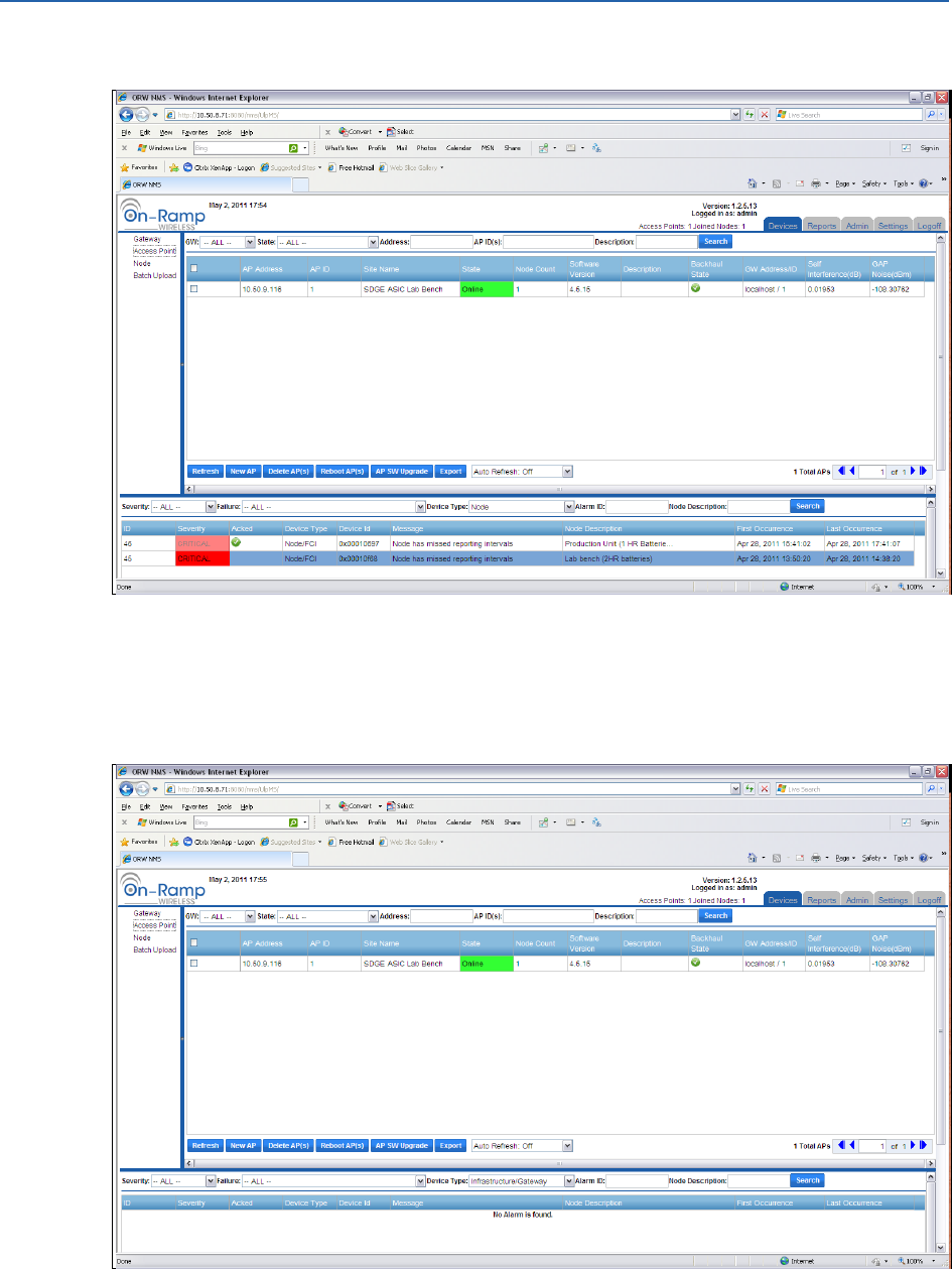
ULP EMS Operator Guide Maintaining and Operating the ULP Network
On-Ramp Wireless Confidential and Proprietary 49 010-0045-00
4. Click Yes.
Depending on the settings for the email system notification group, the operator may receive
emails for combinations of acknowledgement, clearing, and/or lack of acknowledgement.
After the cause of the alarm is cleared, the alarm will be cleared. There are not any active
alarms displayed in the window.
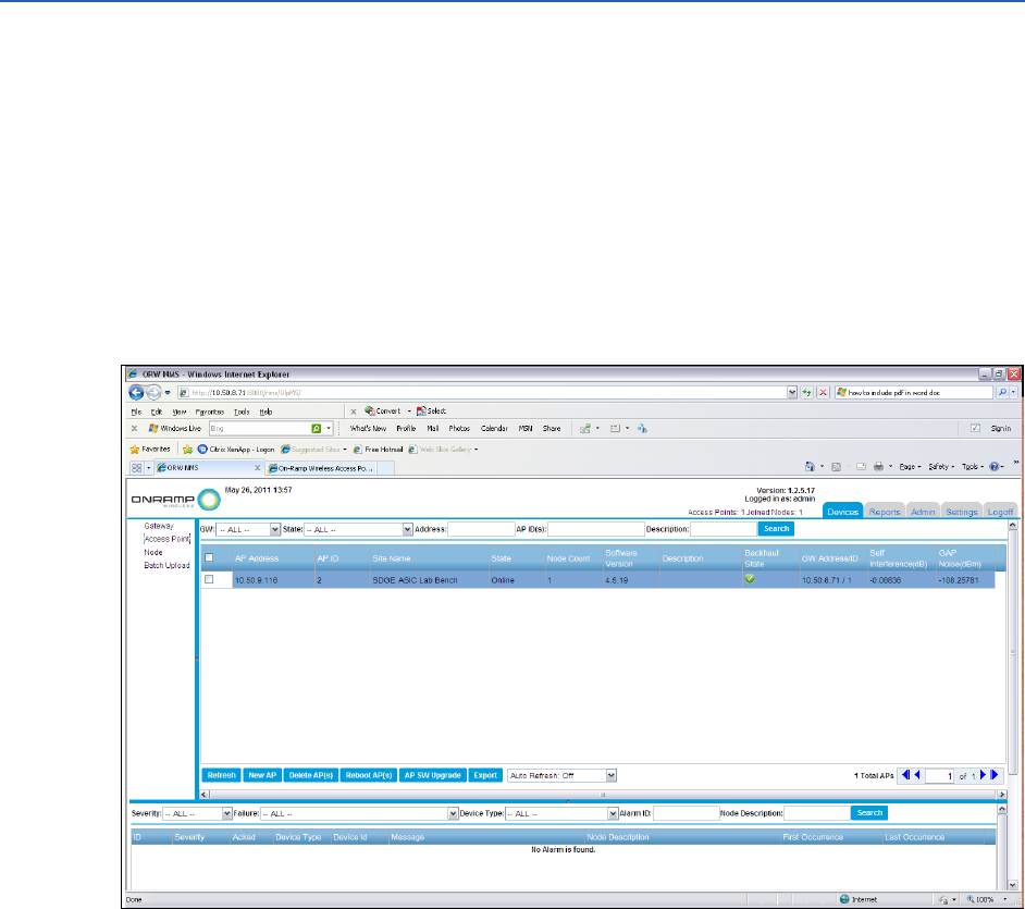
ULP EMS Operator Guide Maintaining and Operating the ULP Network
On-Ramp Wireless Confidential and Proprietary 50 010-0045-00
3.6.5 EMS Alarm History
The EMS keeps the history of alarms for each element in the network. To see the alarm history
for a device in the network, select a device from the device listing, and navigate to the Alarm
History for that device. The following process is the same sequence of steps for Gateways,
Access Points, or Nodes.
In the following example, look at the alarm history of an Access Point.
1. To see the history of the alarm, click the Devices tab in the main window.
2. To see the APs in the system, click Access Point in the Devices pane.
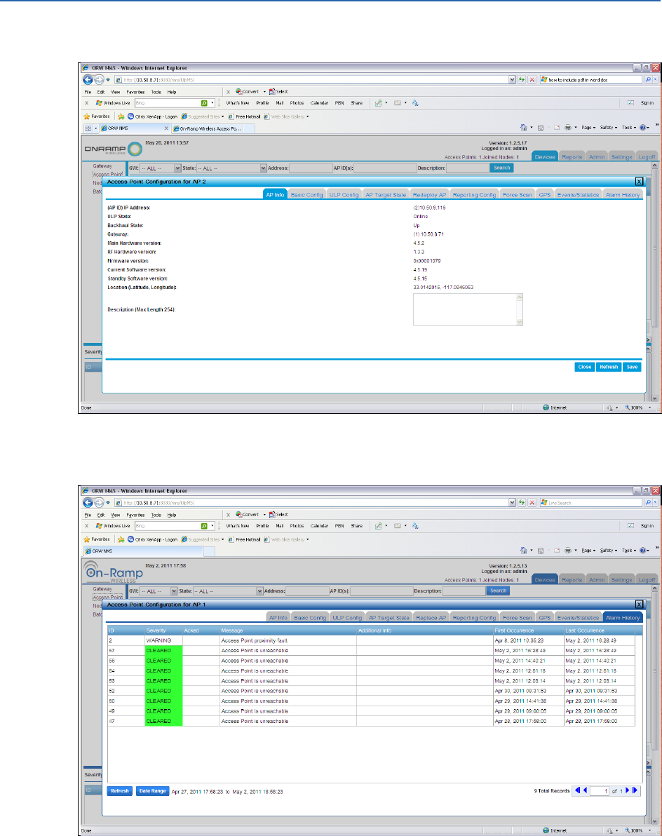
ULP EMS Operator Guide Maintaining and Operating the ULP Network
On-Ramp Wireless Confidential and Proprietary 51 010-0045-00
3. From the devices list, select the Access Point.
4. Click the Alarm History tab. In the following example, the original alarm is listed and is
followed by the Cleared event after the cause for the alarm was fixed.
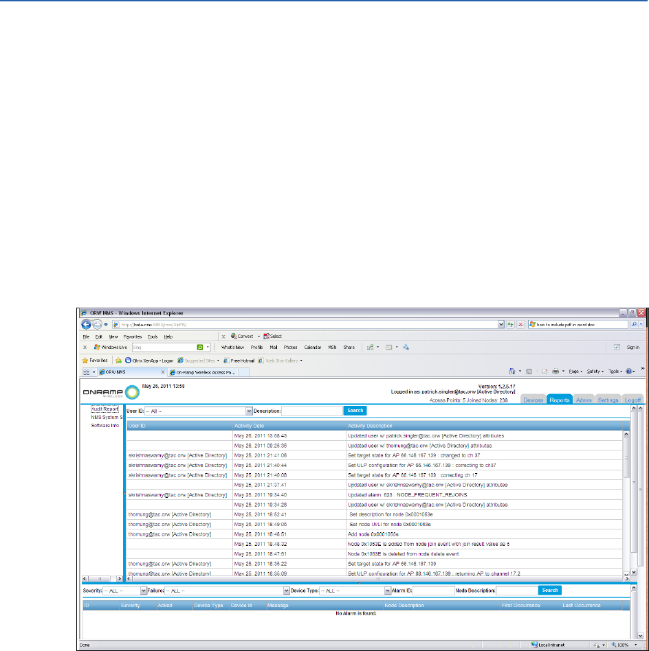
ULP EMS Operator Guide Maintaining and Operating the ULP Network
On-Ramp Wireless Confidential and Proprietary 52 010-0045-00
3.7 Audit Reporting
The EMS includes a System Audit Reporting feature. This feature captures a log item each time
devices are added, devices are removed, or a ULP system configuration parameter is set and/or
changed. This reporting feature is useful when there are multiple system operators who need to
verify when system changes may have been made that they are not aware of. This feature also
allows system administrators access to a historical record of system configuration changes that
is searchable and downloadable for offline processing.
To access the EMS audit reporting capability, complete the following steps:
1. Log in to the EMS with a valid account. Any account type (admin, operator, or guest) can
access the EMS audit reporting since there is no capability to change what the system logs.
2. Click the Reports tab. If it is not automatically highlighted, select Audit Report in the Device
Selection Pane.
As shown above, the Device Listing Pane of the EMS display shows a list of historical system
configuration actions. Each row contains an entry for:
User ID: This field indicates which user account made this change.
Activity Date: This field records what date and time this change was made.
Activity Description: This field records what the user entered in the pop-up window and
when the change was made.
To facilitate real-time searches, the top of the Device Listing Pane contains a drop-down list
which allows the operator to sort by User ID. There is also a Search field which allows the
operator to search for items in the Activity Description field of the audit report.
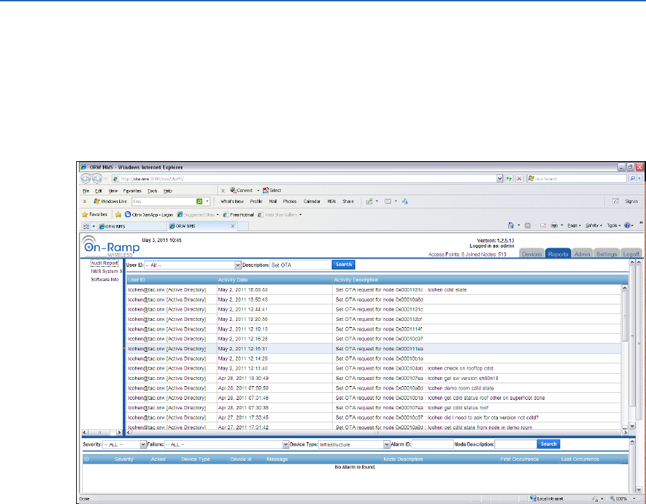
ULP EMS Operator Guide Maintaining and Operating the ULP Network
On-Ramp Wireless Confidential and Proprietary 53 010-0045-00
To facilitate practical searching, each Activity Description entry contains two parts to the text
captured in the field. For each type of system change, there is a fixed description as well as an
optional description that is appended to this field. The optional description is the information
that the operator enters in the pop-up window that accompanies a system change.
For example, as shown below, a search was performed on the keyword, Set OTA. The search
resulted in the following:
There are two types of entries shown.
Row 1 shows an example that contains the fixed system entry: Set OTA request for node
0x0001131c as well as the optional entry that this user made when they affected this
system change: lcohen cdld state.
Rows 2-8 show system changes where the user did not enter optional descriptions at the
time of the system change.
When using the audit reporting feature of EMS, the date set by the Date Range button must
include the dates of interest. The Export button allows the operator to export the list of items
contained in the current Date Range setting to a Comma Separated Value (CSV) text file.
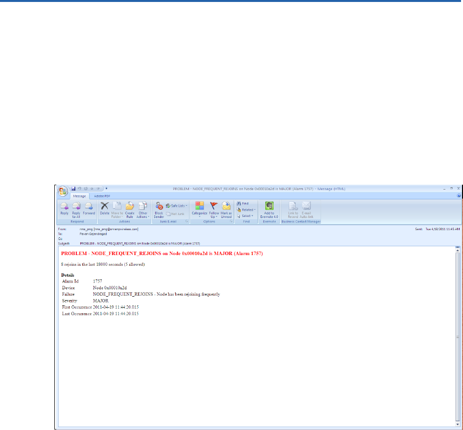
On-Ramp Wireless Confidential and Proprietary 54 010-0045-00
Appendix A Typical Email Alert Alarm Email
The EMS alarm system will generate a specific email for each type of alarm that the system can
generate. Depending on the configuration of the email system, the operator may receive
reminder emails, acknowledgement emails, and cleared emails from the system.
The following four examples show the path of a single type of alarm (NODE FREQUENT REJOIN)
and include:
A NODE FREQUENT REJOIN alarm email
A reminder for this alarm
An acknowledgement of this alarm
An email showing the alarm has been cleared
Figure 3. NODE FREQUENT REJOIN Alarm Email
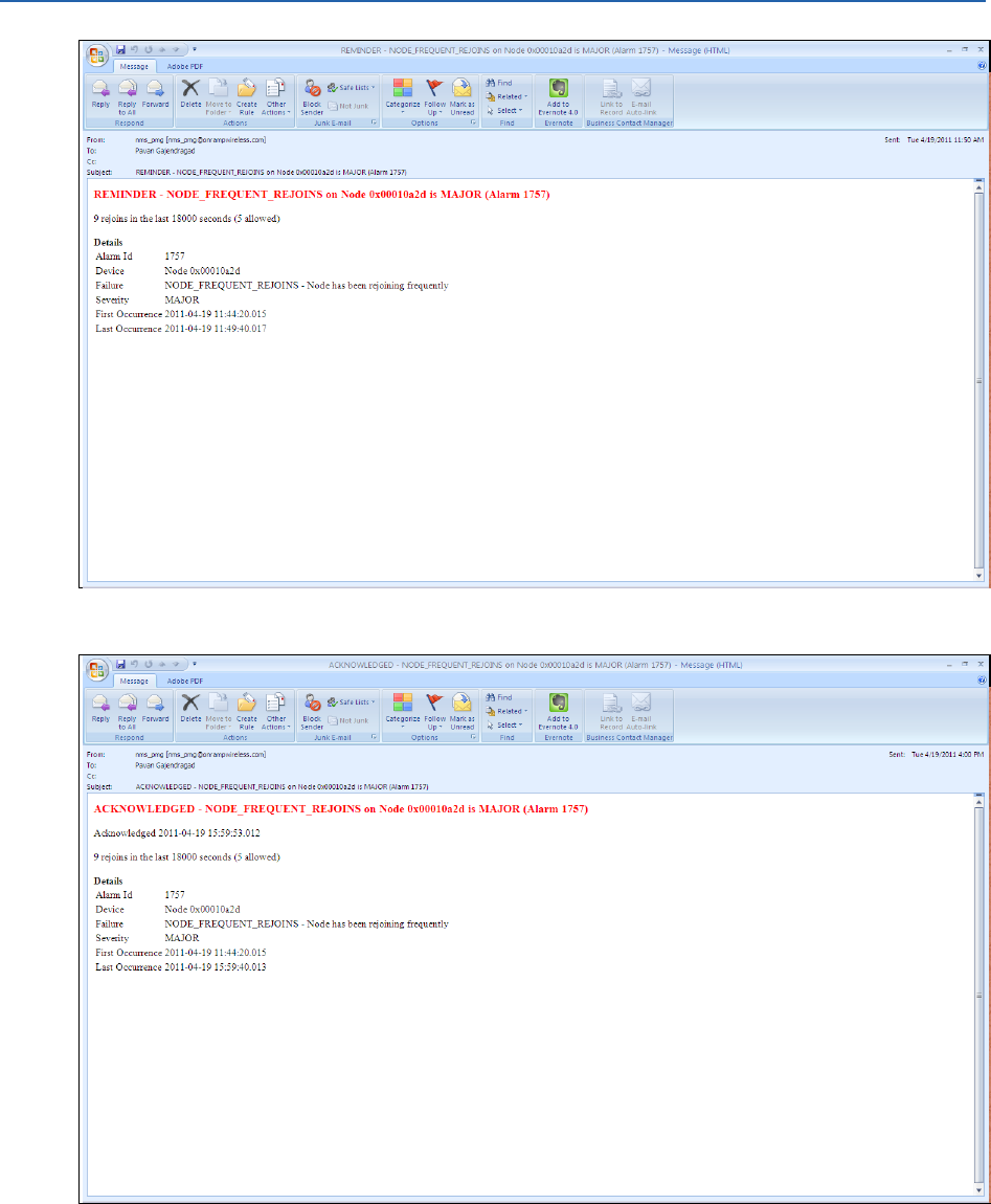
ULP EMS Operator Guide Typical Email Alert Alarm Email
On-Ramp Wireless Confidential and Proprietary 55 010-0045-00
Figure 4. Reminder for the Alarm
Figure 5. Acknowledgement of the Alarm
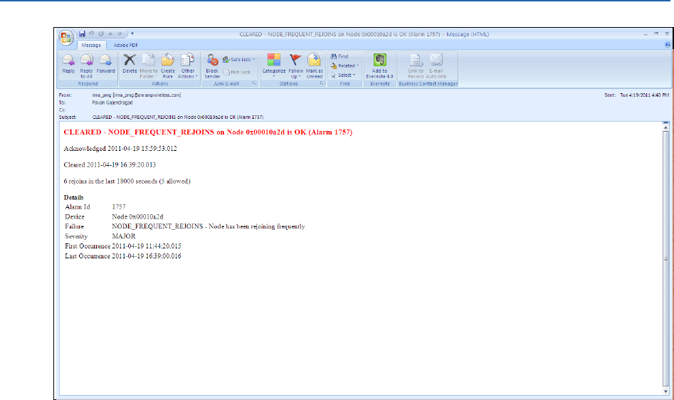
ULP EMS Operator Guide Typical Email Alert Alarm Email
On-Ramp Wireless Confidential and Proprietary 56 010-0045-00
Figure 6. Email Showing the Cleared Alarm
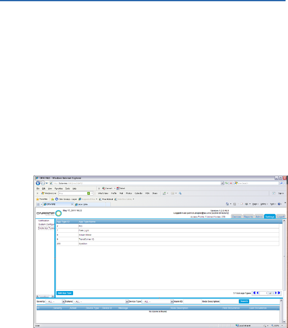
On-Ramp Wireless Confidential and Proprietary 57 010-0045-00
Appendix B New Application Types
The initial release of the EMS supports the following application types in this documented
release:
1. App Type ID: 2 – FCI
2. App Type ID: 7 – FAA
3. App Type ID: 8 – Smart Meter
4. App Type ID: 9 – Transformer IQ
5. App Type ID: 255 – Sysmon
6. App Type ID: 2 – FCI
Over time, new applications will be identified to be added to the ULP system. The EMS facilitates
a way to add device types to the system.
NOTE:
New devices can be added to the EMS and CIMA. For more information about adding
new device types to CIMA, see the CIMA Operator Guide.
1. To add a new device type in the EMS, log in as an administrator.
2. Click the Settings tab.
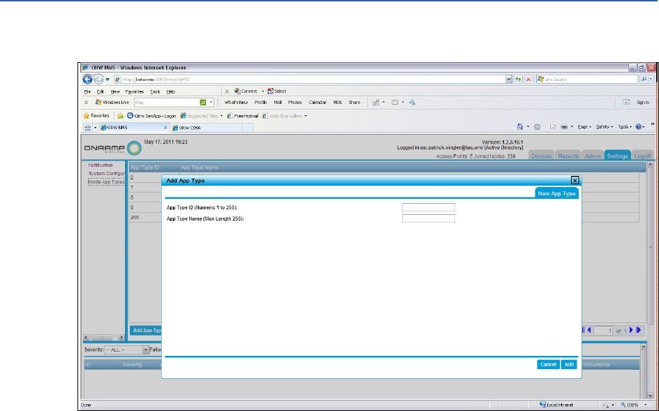
ULP EMS Operator Guide New Application Types
On-Ramp Wireless Confidential and Proprietary 58 010-0045-00
3. Select Add App Type, and complete the field entries.

On-Ramp Wireless Confidential and Proprietary 59 010-0045-00
Appendix C Abbreviations and Terms
Abbreviation/Term
Definition
AP
Access Point. The ULP network component geographically deployed
over a territory.
CIMA
Critical Infrastructure Monitoring Application. The network component
that passes data from the Gateway to the associated upstream
databases.
CSV
Comma Separated Value
Dashboard
Web page view of the aggregated end-device monitoring data.
DBA
Database Administrator
FCI
Fault Circuit Indicator. The Schweitzer Engineering Laboratories (SEL®)
designed end device that remotely monitors distribution lines for
voltage and/or current faults.
GW
Gateway. The network appliance that provides a single entry point into
the back office for the ULP network. A gateway talks upstream to the
EMS and CIMA. It talks downstream to multiple APs.
IT
Information Technology
KMS
Key Management Server
EMS
Element Management System. The network component that provides a
concise view of the ULP network for controls and alarms.
Node
The generic term used interchangeably with end point device.
ORW
On-Ramp Wireless
RMU
Remote Monitoring Unit. The end device that monitors Federal Aviation
Administration (FAA) obstruction lights.
TCP/IP
Transmission Control Protocol/Internet Protocol
ULP
Ultra-Link Processing. The ORW proprietary wireless communication
technology.