Ingersoll Rand 7120 Users Manual
7120 to the manual bdd0c08e-93bd-4f33-ad82-71c891a70350
2015-01-23
: Ingersoll-Rand Ingersoll-Rand-7120-Users-Manual-342448 ingersoll-rand-7120-users-manual-342448 ingersoll-rand pdf
Open the PDF directly: View PDF ![]() .
.
Page Count: 76
7/120, 9/110, 10/105, 14/85
7/170, 10/125, 14/115
This manual contains
important safety information
and must be made available to
personnel who operate and
maintain this machine.
7/120 9/110 –>SERIAL No : 32000110/105 14/85
C.C.N. : 22191225 GB
DATE : SEPTEMBER 2003
OPERATION AND MAINTENANCE MANUAL
7/170 10/125 14/115

Machine models represented in this manual may be used in various locations world–wide. Machines sold
and shipped into European Union Territories require that the machine display the EC Mark and conform
to various directives. In such cases, the design specification of this machine has been certified as
complying with EC directives. Any modification to any part is absolutely prohibited and would result in
the CE Certification and marking being rendered invalid. A declaration of that conformity follows:
DECLARATION OF CONFORMITY WITH EC DIRECTIVES
We
Declare that, under our sole responsibility for manufacture and supply, the product(s)
98/37/EC, 93/68/EEC, 89/336/EEC
Ingersoll–Rand Company
P.O. Box 868
501 Sanford Avenue
Mocksville, North Carolina 27028
Ingersoll–Rand Company Limited
Swan Lane
Hindley Green
Wigan WN2 4EZ
United Kingdom
Represented in EC by:
to which this declaration relates, is (are) in conformity with the provisions of the above
directives using the following principal standards
Issued at Mocksville on
1–1–2003 Issued at Hindley Green on
1–1–2003
EN29001 : EN292, EN60204–1, EN1012–1, PN8NTC2, EN50081, EN50082
________________________________ ________________________________
7/120 (P425AWIR) 9/110 (XP375AWIR) 10/105 (HP375AWIR)
14/85 (VHP300AWIR)
Harry Seddon
Quality assurance manager
Ric Lunsford
Manager of quality control
CONFORMITY WITH NOISE DIRECTIVE 2000/14/EC
Ingersoll–Rand Company Limited declare that the following Portable Compressors have been
manufactured in conformity with the directive as shown
Machine Mean Guaranteed
Directive Type kW measured
value
Guaranteed
Level Notified body
14/85WIR
2000/14/EC 10/105WIR A V Technology
Annex VI
Part I 9/110WIR 93 100.2 LWA 101 LWA Stockport UK
Nr 1067Part I 7/120WIR Nr 1067
________________________________
Issued at Mocksville, NC. . . . . . . . .
1st Declaration January 11, 2003. . . . Ric Lunsford
Manager of quality control
EC Pressure Equipment Directive and Related Regulations
We declare that this product has been assessed according to the Pressure Equipment Directive (97/23/EC)
and, in accordance with the terms of this Directive, has been excluded from the scope of this Directive.
It may carry ”CE” marking in compliance with other applicable EC Directives.
Machine models represented in this manual may be used in various locations world–wide. Machines sold
and shipped into European Union Territories require that the machine display the EC Mark and conform
to various directives. In such cases, the design specification of this machine has been certified as
complying with EC directives. Any modification to any part is absolutely prohibited and would result in
the CE Certification and marking being rendered invalid. A declaration of that conformity follows:
We
Declare that, under our sole responsibility for manufacture and supply, the product(s)
98/37/EC, 93/68/EEC, 89/336/EEC
Ingersoll–Rand Company
P.O. Box 868
501 Sanford Avenue
Mocksville, North Carolina 27028
Ingersoll–Rand Company Limited
Swan Lane
Hindley Green
Wigan WN2 4EZ
United Kingdom
Represented in EC by:
to which this declaration relates, is (are) in conformity with the provisions of the above
directives using the following principal standards
Issued at Mocksville on
1–1–2003 Issued at Hindley Green on
1–1–2003
EN29001 : EN292, EN60204–1, EN1012–1, PN8NTC2, EN50081, EN50082
________________________________ ________________________________
7/170 (P600WIR) 10/125 (HP450WIR) 14/115 (VHP400WIR)
Harry Seddon
Quality assurance manager
Ric Lunsford
Manager of quality control
DECLARATION OF CONFORMITY WITH EC DIRECTIVES
CONFORMITY WITH NOISE DIRECTIVE 2000/14/EC
Ingersoll–Rand Company Limited declare that the following Portable Compressors have been
manufactured in conformity with the directive as shown
Machine Mean Guaranteed
Directive Type kW measured
value
Guaranteed
Level Notified body
2000/14/EC
14/115
A V Technology
2000/14/EC
Annex VI 10/125 126.5 100.2 LWA 101 LWA
A V Technology
Stockport UK
Part I 7/170 WA WA Nr 1067
________________________________
Issued at Mocksville, NC. . . . . . . . .
1st Declaration January 11, 2003. . . . Ric Lunsford
Manager of quality control
EC Pressure Equipment Directive and Related Regulations
We declare that this product has been assessed according to the Pressure Equipment Directive (97/23/EC)
and, in accordance with the terms of this Directive, has been excluded from the scope of this Directive.
It may carry ”CE” marking in compliance with other applicable EC Directives.

17/120 (P425AWIR), 9/110 (XP375AWIR), 10/105 (HP375AWIR), 14/85 (VHP300AWIR),
7/170 (P600WIR), 10/125 (HP450WIR), 14/115 (VHP400WIR)
1 CONTENTS
2 FOREWORD
3 WARRANTY
9 DECALS
13 SAFETY
16 GENERAL INFORMATION
Dimensions
Data
21 OPERATING INSTRUCTIONS
Commissioning
Prior to starting
Starting
Stopping
Emergency stopping
Re–starting
Monitoring during operation
Decommissioning
29 ENGINE INSTRUCTION MANUAL
46 MAINTENANCE
Routine maintenance
Lubrication
Speed & pressure regulation
Torque settings table
Compressor lubrication
58 MACHINE SYSTEMS
Electrical system
Piping & instrumentation system
61 SERVICE TOOLS
65 FAULT FINDING
67 OPTIONS
70 PARTS ORDERING
ABBREVIATIONS & SYMBOLS
#### Contact Ingersoll–Rand for serial
number
–>#### Up to Serial No.
####–>From Serial No.
*Not illustrated
†Option
AR As required
DGermany
DK Denmark
ESpain
FFrance
GB Great Britain
HA High ambient machine
IItaly
NNorway
NL Netherlands
PPortugal
SSweden
SF Finland
F.H.R.G. Fixed height running gear
V.H.R.G. Variable height running gear

2
7/120 (P425AWIR), 9/110 (XP375AWIR), 10/105 (HP375AWIR), 14/85 (VHP300AWIR),
7/170 (P600WIR), 10/125 (HP450WIR), 14/115 (VHP400WIR)
FOREWORD
The contents of this manual are considered to be proprietary
and confidential to Ingersoll–Rand and should not be
reproduced without the prior written permission of
Ingersoll–Rand.
Nothing contained in this document is intended to extend any
promise, warranty or representation, expressed or implied,
regarding the Ingersoll–Rand products described herein. Any
such warranties or other terms and conditions of sale of
products shall be in accordance with the standard terms and
conditions of sale for such products, which are available upon
request.
This manual contains instructions and technical data to
cover all routine operation and scheduled maintenance tasks by
operation and maintenance staff. Major overhauls are outside
the scope of this manual and should be referred to an authorised
Ingersoll–Rand service department.
The design specification of this machine has been certified
as complying with EC directives. As a result:
(a) Any machine modifications are strictly prohibited, and will
invalidate EC certification.
(b) A unique specification for USA/Canada is adopted and
tailored to the territory.
All components, accessories, pipes and connectors added
to the compressed air system should be:
. of good quality, procured from a reputable manufacturer and,
wherever possible, be of a type approved by Ingersoll–Rand.
. clearly rated for a pressure at least equal to the machine
maximum allowable working pressure.
. compatible with the compressor lubricant/coolant.
. accompanied with instructions for safe installation,
operation and maintenance.
Details of approved equipment are available from
Ingersoll–Rand Service departments.
The use of repair parts / lubricants / fluids other than those
included within the Ingersoll–Rand approved parts list may
create hazardous conditions over which Ingersoll–Rand has no
control. Therefore Ingersoll–Rand cannot be held responsible
for equipment in which non–approved repair parts are installed.
Ingersoll–Rand reserves the right to make changes and
improvements to products without notice and without incurring
any obligation to make such changes or add such
improvements to products sold previously.
The intended uses of this machine are outlined below and
examples of unapproved usage are also given, however
Ingersoll–Rand cannot anticipate every application or work
situation that may arise.
IF IN DOUBT CONSULT SUPERVISION.
This machine has been designed and supplied for use only in
the following specified conditions and applications:
.Compression of normal ambient air containing no known or
detectable additional gases, vapours. or particles
.Operation within the ambient temperature range specified in
the GENERAL INFORMATION section of this manual.
UNITS MANUFACTURED IN NORTH AMERICA: Generation
of electricity at 120V (1ph) at 60 Hertz.
UNITS MANUFACTURED IN EUROPE: Generation of
electricity not applicable.
The use of the machine in any of the situation types
listed in table 1:–
a) Is not approved by Ingersoll–Rand,
b) May impair the safety of users and other persons, and
c) May prejudice any claims made against Ingersoll–Rand.
TABLE 1
Use of the machine to produce compressed air for:
a) direct human consumption
b) indirect human consumption, without suitable filtration and
purity checks.
Use of the machine outside the ambient temperature range
specified in the GENERAL INFORMATION SECTION of this
manual.
This machine is not intended and must not be used in
potentially explosive atmospheres, including situations where
flammable gases or vapours may be present.
Use of the machine fitted with non Ingersoll–Rand approved
components / lubricants / fluids.
Use of the machine with safety or control components
missing or disabled.
Use of the machine for storage or transportation of materials
inside or on the enclosure except when contained within the
toolbox.
GENERATOR
Use of the generator to supply load(s) greater than those
specified.
Use of unsafe or unserviceable electrical equipment
connected to the generator.
Use of electrical equipment:
(a) Having incorrect voltage and/or frequency ratings.
(b) Containing computer equipment and/or similar electronics.
The company accepts no responsibility for errors in
translation of this manual from the original English version.
COPYRIGHT 2003
INGERSOLL–RAND COMPANY

37/120 (P425AWIR), 9/110 (XP375AWIR), 10/105 (HP375AWIR), 14/85 (VHP300AWIR),
7/170 (P600WIR), 10/125 (HP450WIR), 14/115 (VHP400WIR)
WARRANTY
Ingersoll–Rand, through its distributor, warrants that each item
of equipment manufactured by it and delivered hereunder to the
initial user will be free of defects in material and workmanship.
With respect to the following types of equipment, the warranty
period enumerated below will apply.
A. Aftercoolers – The earlier of nine (9) months from date
of shipment to or six (6) months from start up by initial user.
B. Portable Compressors, Portable Generator Sets
(GENSET), Portable Light Towers and Air Dyers – The
earlier of twelve (12) months from shipment to or the
accumulation of 2,000 hours of service by the initial user.
C. Portable Compressor Air Ends – The earlier of
twenty–four (24) months from shipment to or the
accumulation of 4,000 hours of service by the initial user.
For Air Ends, the warranty against defects will include
replacement of the complete Air End, provided the original
Air End, is returned assembled and unopened.
C.1 Portable Compressor Airend Limited Optional
Warranty – The earlier of sixty (60) months from shipment
to or the accumulation of 10,000 hours of service. The
optional warranty is limited to defects in rotors, housings,
bearings and gears and provided all the following
conditions are met:
The original airend is returned assembled and unopened.
Continued use of genuine Ingersoll–Rand parts, fluids,
oils and filters.
Maintenance is performed at prescribed intervals.
D. Genset Generators – The earlier of twenty–four (24)
months from shipment to or the accumulation of 4,000
hours of service by the initial user.
E. Portable Light Tower Generators – The earlier of twelve
(12) months from shipment to or the accumulation of 2,000
hours of service by the initial user. Light Source model
only, the earlier of twenty–four (24) months from shipment
to or the accumulation of 4,000 hours of service.
F. Ingersoll–Rand Engines – The earlier of twenty—four
(24) months from shipment to or the accumulation of 4,000
hours of service.
G. Ingersoll–Rand Platinum Drive Train Warranty
(Optional) – Platinum drive train pertains to the
Ingersoll–Rand Engine and Airend combination. The
earlier of sixty (60) months from shipment to, or the
accumulation of 10,000 hours of service. The starter,
alternator, fuel injection system and all electrical
components are excluded from the extended warranty.
The airend seal and drive coupling are included in the
warranty (air–end drive belts are not included). The
optional warranty is automatically available when meeting
the following conditions:
The original airend is returned assembled and unopened.
Continued use of genuine Ingersoll–Rand parts, fluids, oil
and filters.
Maintenance is performed at prescribed intervals.
It is the obligation of the user to provide verification that
these conditions have been satisfied when submitting
warranty claims.
H. Spare Parts – Six (6) months from date of installation
Ingersoll–Rand will provide a new part or repaired part, at its
election, in place of any part which is found upon its inspection
to be defective in material and workmanship during the period
prescribed above. Such part will be repaired or replaced without
charge to the initial user during normal working hours at the
place of business of an Ingersoll–Rand distributor authorized to
sell the type of equipment involved or other establishment
authorized by Ingersoll – Rand. User must present proof of
purchase at the time of exercising warranty.
The above warranty does not apply to failures occurring as a re-
sult of abuse; misuse, negligent repairs, corrosion, erosion and
normal wear and tear, alterations or modifications made to the
product without express written consent of Ingersoll–Rand; or
failure to follow the recommended operating practices and
maintenance procedures as provided in the product’s operating
and maintenance publications.
Accessories or equipment furnished by Ingersoll–Rand, but
manufactured by others, including, but not limited to, engines,
tires, batteries, engine electrical equipment, hydraulic
transmissions, carriers, shall carry whatever warranty the
manufacturers have conveyed to Ingersoll–Rand and which
can be passed on to the initial user.
THIS WARRANTY IS IN LIEU OF ALL OTHER
WARRANTIES EXPRESSED OR IMPLIED, (EXCEPT THAT
OF TITLE), AND THERE ARE NO WARRANTIES OF
MERCHANTABILITY OR OF FITNESS FORA PARTICULAR
PURPOSE.

4
7/120 (P425AWIR), 9/110 (XP375AWIR), 10/105 (HP375AWIR), 14/85 (VHP300AWIR),
7/170 (P600WIR), 10/125 (HP450WIR), 14/115 (VHP400WIR)
GENERAL WARRANTY INFORMATION
GENERAL WARRANTY Extended Coverage
Portable Compressor Package 1 year/2000 hrs
Airend 2 yrs/4000 hrs 5 yrs/10,000 hrs
Limited warranty, major compo-
nents (refer to operator’s manual).
Portable Genset 8kW, 11KW,
20KVA thru 575KVA Package 1 yr/2000 hrs None
Generator 2 yrs/4000 hrs None
Portable Genset 3.5KW thru
7.0KW and 10KW Package 1 yr/2000 hrs (parts only) None
Generator 1 yrs/2000 hrs (parts only) None
Light Tower Package 1 yr/2000 hrs
Generator 1 yr/2000 hrs 2 years/4000 hours, for Lightsource
introduced 8/16/99.
ENGINES
CATERPILLAR Months Hours Extended Coverage
12 unlimited Available at dealer
CUMMINS 24 2000 Major components 3 yrs/10,000 hrs
Available at dealer
JOHN DEERE (in compressors) 24 2000 5 yrs/5000 hrs using OEM fluids and filters
with $250 deductible
(in generators as of 1/1/01) 24 2000 2 yrs/4000 hrs using IR fluids and filters
DEUTZ 24 2000 Available at dealer
INGERSOLL–RAND 24 4000 5 yrs/10,000 hrs when using genuine Inger-
soll–Rand fluids and parts. Refer to operator’s
manual.
KUBOTA (North America only) 24 2000 Major components 36 mo/3000 hrs (parts only)
(Western Europe & Oceania) 24 2000 None
(Central & South America, Asia, Middle East &
Africa) 12 1000 None
MITSUBISHI 24 2000 2 yrs/4000 hrs using IR fluids and filters
VOLVO 24 2000 2 yrs/4000 hrs using IR fluids and filters
HONDA 12 unlimited None
VANGUARD 24 unlimited None

57/120 (P425AWIR), 9/110 (XP375AWIR), 10/105 (HP375AWIR), 14/85 (VHP300AWIR),
7/170 (P600WIR), 10/125 (HP450WIR), 14/115 (VHP400WIR)
PARTS
Months Hours Coverage
Ingersoll–Rand 6 No Limit Parts Only
AIREND EXCHANGE
Months Hours Extended Coverage
Airend 12 2000 2 yrs/4000 hrs – available from
IR.
Note: Actual warranty times may change. Consult the manufacturer’s warranty policy as shipped with
each new product.
6
7/120 (P425AWIR), 9/110 (XP375AWIR), 10/105 (HP375AWIR), 14/85 (VHP300AWIR),
7/170 (P600WIR), 10/125 (HP450WIR), 14/115 (VHP400WIR)
Extended Limited Airend Warranty
Ingersoll–Rand Portable Compressor Division is pleased to announce the availability of extended limited airend warranty.
Announcement of the extended warranty coincides with the introduction of Pro–Te c Compressor Fluid. Pro–Tec Compressor Fluid
is an amber coloured fluid specially formulated for Portable Compressors and is being provided as the factory filled fluid for all machines
except 1 XHP650/900/1070
All machines have the standard airend warranty, – The earlier of 24 months from shipment to, or the accumulation of 4000 hours of
service by the initial user.
The warranty against defects will include replacement of the complete Airend, provided the original Airend is returned assembled and
unopened.
The optional limited warranty is the earlier of 60 months from shipment to, or the accumulation of 10,000 hours of service. The optional
warranty is limited to defects in major components (rotors, housings, gears and bearings), and is automatically available when the
following conditions are met:
1. The original airend is returned assembled and unopened.
2. Submissions of proof that Ingersoll–Rand fluid, filters and separators have been used. Refer to the Operation and Parts manual for
the correct fluids, filters and separator elements required.
3. Submissions of proof that maintenance intervals have been followed.
WARRANTY TIME *BARE AIREND **AIREND COMPONENTS
STANDARD 2YRS / 4,000HRS 100% PARTS & LABOUR 100% PARTS & LABOUR
OPTIONAL 5YRS / 10,000HRS 100% PARTS & LABOUR 0%
*BARE AIREND – pertains to major airend parts (rotors, housings, gears and bearings).
**AIREND COMPONENTS – pertains to auxiliary attachments to the bare airend (seals, pumps, valves, tubes, hoses, fittings and filter
housing).
Pro–Tec and XHP505 Compressor Fluids are available from your local Ingersoll–Rand branch or distributor.
For units operating within the USA & Canada, call the Mocksville Product Support Department on 1–800–633–5206
1 XHP650/900/1070 will continue to use XHP505 and will have the extended warranty when above conditions are met.

77/120 (P425AWIR), 9/110 (XP375AWIR), 10/105 (HP375AWIR), 14/85 (VHP300AWIR),
7/170 (P600WIR), 10/125 (HP450WIR), 14/115 (VHP400WIR)
WARRANTY REGISTRATION
FOR UNITS SOURCED FROM HINDLEY GREEN, UK
Complete Machine Registration
To initiate the machine warranty, fill out the ”Warranty Registration” form 83242 11/99 supplied as part of the machine documentation,
keep a copy for your records and mail the original to:
Ingersoll Rand European Sales Ltd
Portable Power Business
Swan Lane
Hindley Green
Wigan
Lancashire
WN2 4EZ
U.K.
Attn: Customer Service Department
Note: Completion of this form validates the warranty.
Engine Registration:
I–R powered machines do not require separate engine registration.
Deutz require a separate engine registration form to be completed and mailed direct to their Cologne office. The form is supplied as part
of the machine documentation for Deutz powered machines.
Caterpillar, Cummins and Perkins do not require a separate registration form but they stipulate that any new engine should be registered
with their local dealer to initiate warranty.
You MUST provide proof of the “in–service” date when requesting engine warranty repairs.
8
7/120 (P425AWIR), 9/110 (XP375AWIR), 10/105 (HP375AWIR), 14/85 (VHP300AWIR),
7/170 (P600WIR), 10/125 (HP450WIR), 14/115 (VHP400WIR)
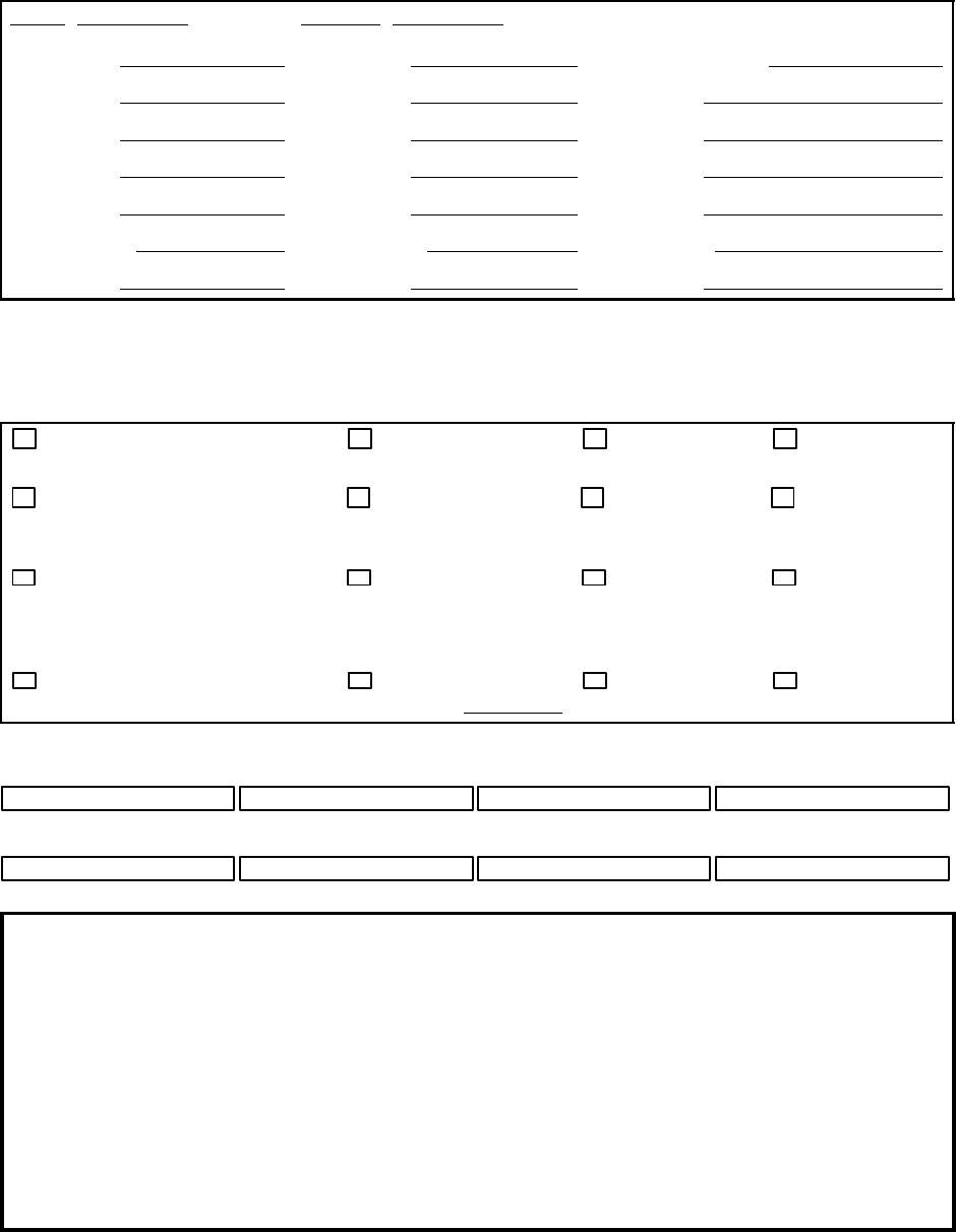
Selling Distributor Servicing Distributor WARRANTY REGISTRATION
Name Name Owner/User Name
Address Address Address
City City City
County County County
State State State
Zip code Zip code Zip code
Telephone Telephone Telephone
Complete the Applicable Blocks
Owner/User Type of Business (check one only)
Construction–Heavy
(highway, excavation, etc.) Asphalt Contractor Coal Mining Other Mining
Construction–Light
(carpentry, plumbing, pools,
mason, etc.)
Government
(municipal, state,
county, etc.)
Quarry Shallow Oil &
Gas
Rental (rental center, rental
fleet, etc.) Building Contractor Water well Utility
Company
(gas, electric,
water, etc.)
Industrial
(plant use) Other
specify Exploration Utility
Contractor
Model S/N Unit S/N Engine S/N Date delivered
Unit–Hours Airend S/N Truck S/N Truck Engine S/N
SERVICING DISTRIBUTOR / USER ACKNOWLEDGEMENT
1. The Purchaser has been instructed and/or has read the manual and understands proper preventative
maintenance, general operation and safety precautions.
2. The warranty and limitation of liability has been reviewed and understood by the owner/user.
3. In the event that this unit is to be used within a nuclear facility, the owner/user shall notify
Ingersoll–Rand of such use so that Ingersoll–Rand may arrange for appropriate nuclear liability
protection from the owner–licensee of the facility.
4. Ingersoll–Rand reserves the right to make design changes or modifications of Ingersoll–Rand products
at anytime without incurring any obligation to make similar changes or modifications on previously sold
units.
97/120 (P425AWIR), 9/110 (XP375AWIR), 10/105 (HP375AWIR), 14/85 (VHP300AWIR),
7/170 (P600WIR), 10/125 (HP450WIR), 14/115 (VHP400WIR)
DECALS
Look for these signs on machines manufactured in Europe, which point out potential hazards to
the safety of you and others. Read and understand thoroughly. Heed warnings and follow
instructions. If you do not understand, inform you supervisor.
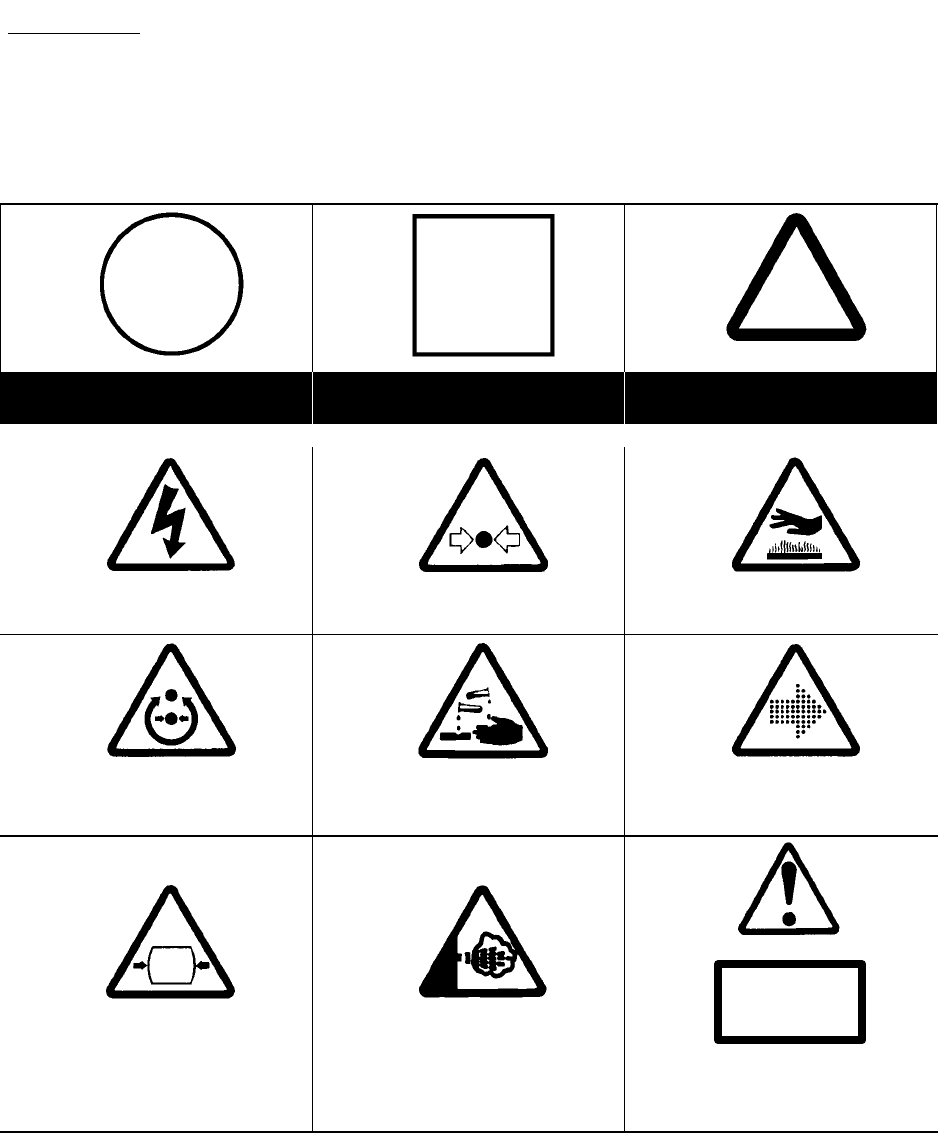
GRAPHIC FORM AND MEANING OF ISO SYMBOLS
Prohibition / Mandatory Information / Instructions Warning
WARNING: Electrical shock risk.WARNING – Pressurised component or
system. WARNING – Hot surface.
WARNING – Pressure control. WARNING – Corrosion risk. WARNING – Air/gas flow or Air
discharge.
X,XBAR
WARNING – Pressurised vessel. WARNING – Hot and harmful exhaust
gas.
WARNING – Maintain correct tyre
pressure. (Refer to the GENERAL
INFORMATION section of this manual).
10
7/120 (P425AWIR), 9/110 (XP375AWIR), 10/105 (HP375AWIR), 14/85 (VHP300AWIR),
7/170 (P600WIR), 10/125 (HP450WIR), 14/115 (VHP400WIR)
0C
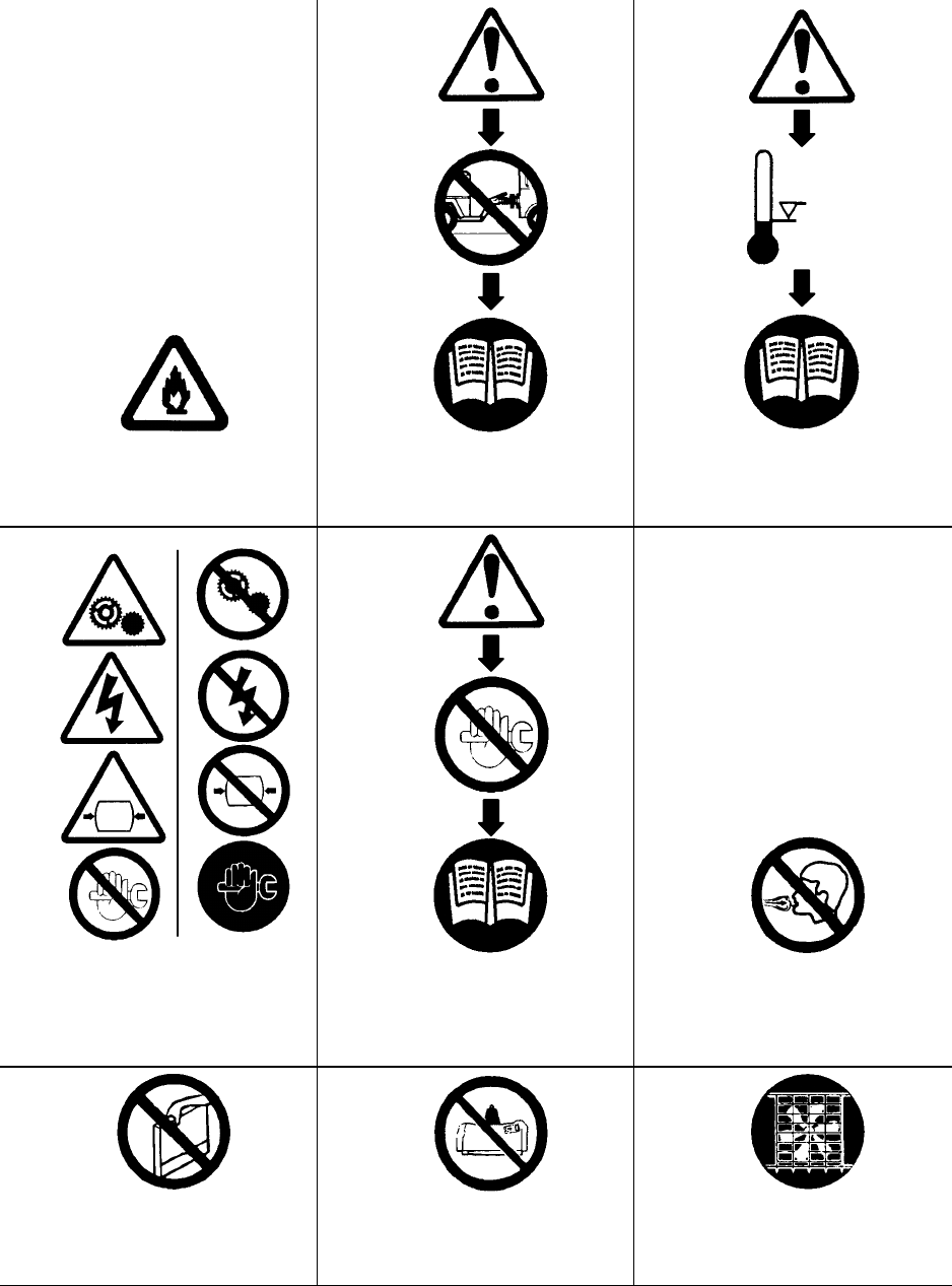
WARNING – Flammable liquid.WARNING – Before connecting the tow
bar or commencing to tow consult the
operation and maintenance manual.
WARNING – For operating temperature
below 0C, consult the operation and
maintenance manual.
WARNING – Do not undertake any
maintenance on this machine until the
electrical supply is disconnected and
the air pressure is totally relieved.
WARNING – Consult the operation and
maintenance manual before
commencing any maintenance.
Do not breathe the compressed air from
this machine.
Do not remove the Operating and
Maintenance manual and manual holder
from this machine. Do not stack. Do not operate the machine without the
guard being fitted.
11 7/120 (P425AWIR), 9/110 (XP375AWIR), 10/105 (HP375AWIR), 14/85 (VHP300AWIR),
7/170 (P600WIR), 10/125 (HP450WIR), 14/115 (VHP400WIR)
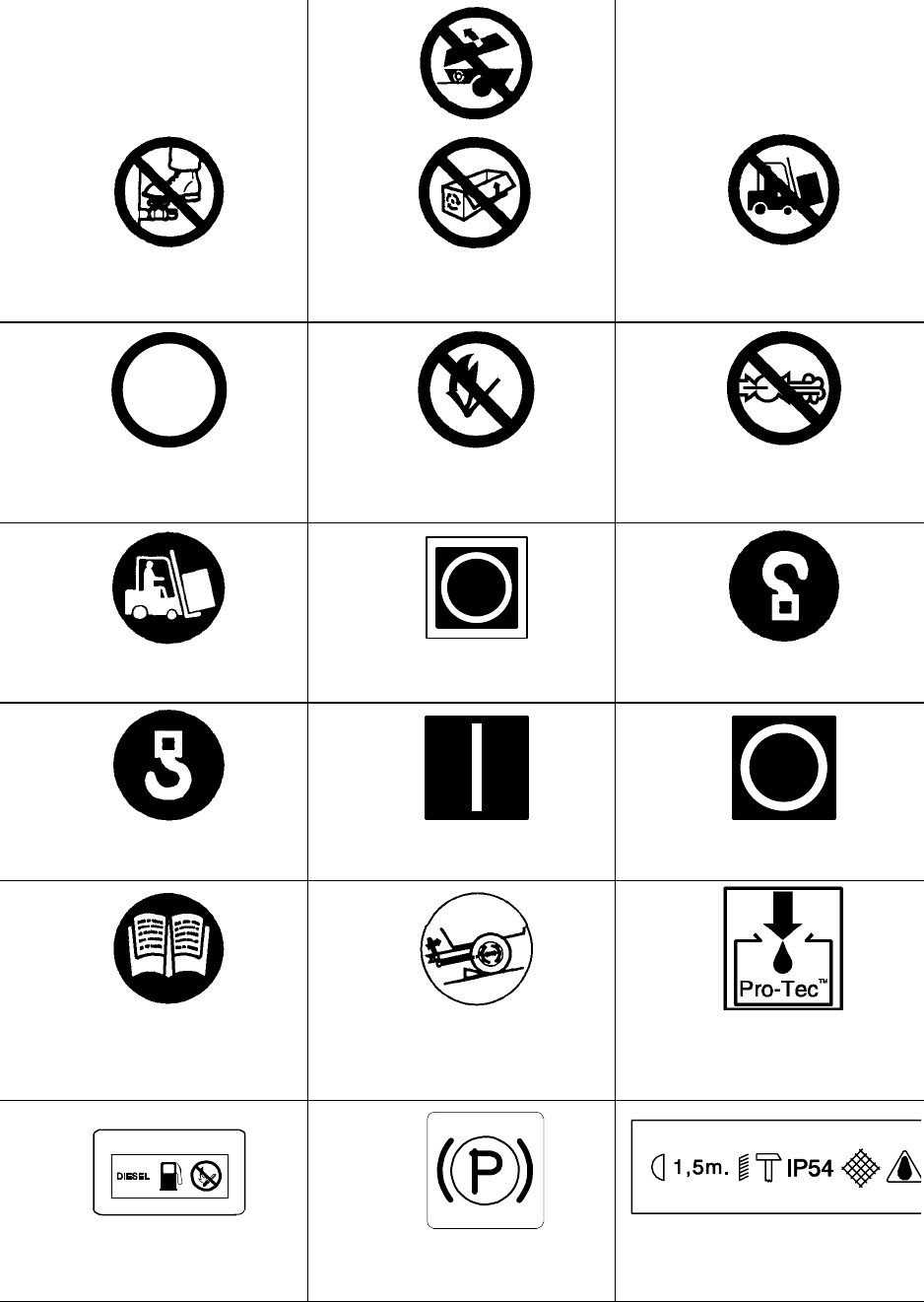
Do not stand on any service valve or other
parts of the pressure system. Do not operate with the doors or enclosure
open. Do not use fork lift truck from this side.
XX
km/h
Do not exceed the trailer speed limit. No naked lights. Do not open the service valve before the
airhose is attached.
Use fork lift truck from this side only. Emergency stop. Tie down point
Lifting point. On (power). Off (power).
Read the Operation and Maintenance
manual before operation or maintenance
of this machine is undertaken.
When parking use prop stand, handrake
and wheel chocks. Compressor oil filling
Diesel fuel
No open flame. Parking brake. Rough Service Designation.
Wet Location Operation.
12
7/120 (P425AWIR), 9/110 (XP375AWIR), 10/105 (HP375AWIR), 14/85 (VHP300AWIR),
7/170 (P600WIR), 10/125 (HP450WIR), 14/115 (VHP400WIR)
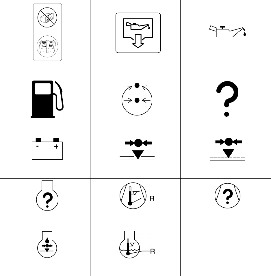
Replace any cracked protective shield. Oil drain. Engine Oil
Fuel level/point Pressure control Malfunction
Battery charging condition Low pressure High pressure
Engine malfunction High compressor temperature Compressor malfunction
Low engine oil pressure Engine high temperature

13 7/120 (P425AWIR), 9/110 (XP375AWIR), 10/105 (HP375AWIR), 14/85 (VHP300AWIR),
7/170 (P600WIR), 10/125 (HP450WIR), 14/115 (VHP400WIR)
SAFETY
WARNINGS
Warnings call attention to instructions which must be
followed precisely to avoid injury or death.
CAUTIONS
Cautions call attention to instructions which must be
followed precisely to avoid damaging the product, process or its
surroundings.
NOTES
Notes are used for supplementary information.
General Information
Never operate unit without first observing all safety warnings
and carefully reading the operation and maintenance manual
shipped from the factory with this machine.
Ensure that the operator reads and understands the decals
and consults the manuals before maintenance or operation.
Ensure that the Operation and Maintenance manual, and the
manual holder, are not removed permanently from the machine.
Ensure that maintenance personnel are adequately trained,
competent and have read the Maintenance Manuals.
Make sure that all protective covers are in place and that the
canopy/doors are closed during operation.
The specification of this machine is such that the machine is
not suitable for use in flammable gas risk areas. If such an
application is required then all local regulations, codes of
practice and site rules must be observed. To ensure that the
machine can operate in a safe and reliable manner, additional
equipment such as gas detection, exhaust spark arrestors, and
intake (shut–off) valves may be required, dependant on local
regulations or the degree of risk involved.
A weekly visual check must be made on all fasteners/fixing
screws securing mechanical parts. In particular, safety–related
parts such as coupling hitch, drawbar components,
road–wheels, and lifting bail should be checked for total
security.
All components which are loose, damaged or unserviceable,
must be rectified without delay.
Air discharged from this machine may contain carbon
monoxide or other contaminants which will cause serious injury
or death. Do not breathe this air.
This machine produces loud noise with the doors open or
service valve vented. Extended exposure to loud noise can
cause hearing loss. Always wear hearing protection when doors
are open or service valve is vented.
Never inspect or service unit without first disconnecting
battery cable(s) to prevent accidental starting.
Do not use petroleum products (solvents or fuels) under high
pressure as this can penetrate the skin and result in serious
illness. wear eye protection while cleaning unit with compressed
air to prevent debris from injuring eye(s).
Rotating fan blade can cause serious injury. Do not operate
without guard in place.
Use care to avoid contacting hot surfaces (engine exhaust
manifold and piping, air receiver and air discharge piping, etc.).
Ether is an extremely volatile, highly inflammable gas. When
it is specified as a starting aid, use sparingly. DO NOT USE
ETHER IF THE MACHINE HAS GLOW PLUGS OR INLET
HEATER STARTING AIDS OR ENGINE DAMAGE WILL
RESULT.
Never operate unit with guards, covers or screens removed.
Keep hands, hair, clothing, tools, blow gun tips, etc. well away
from moving parts.
Compressed air
Compressed air can be dangerous if incorrectly handled.
Before doing any work on the unit, ensure that all pressure is
vented from the system and that the machine cannot be started
accidentally.
Ensure that the machine is operating at the rated pressure
and that the rated pressure is known to all relevant personnel.
All air pressure equipment installed in or connected to the
machine must have safe working pressure ratings of at least the
machine rated pressure.
If more than one compressor is connected to one common
downstream plant, effective check valves and isolation valves
must be fitted and controlled by work procedures, so that one
machine cannot accidently be pressurised / over pressurised by
another.
Compressed air must not be used for a direct feed to any
form of breathing apparatus or mask.
High Pressure Air can cause serious injury or death. Relieve
pressure before removing filler plugs/caps, fittings or covers.
Air pressure can remain trapped in air supply line which can
result in serious injury or death. Always carefully vent air supply
line at tool or vent valve before performing any service.
The discharged air contains a very small percentage of
compressor lubricating oil and care should be taken to ensure
that downstream equipment is compatible.
If the discharged air is to be ultimately released into a
confined space, adequate ventilation must be provided.
When using compressed air always use appropriate
personal protective equipment.
All pressure containing parts, especially flexible hoses and
their couplings, must be regularly inspected, be free from
defects and be replaced according to the Manual instructions.
Avoid bodily contact with compressed air.
The safety valve located in the separator tank must be
checked periodically for correct operation.

14
7/120 (P425AWIR), 9/110 (XP375AWIR), 10/105 (HP375AWIR), 14/85 (VHP300AWIR),
7/170 (P600WIR), 10/125 (HP450WIR), 14/115 (VHP400WIR)
Whenever the machine is stopped, air will flow back into the
compressor system from devices or systems downstream of
the machine unless the service valve is closed. Install a check
valve at the machine service valve to prevent reverse flow in the
event of an unexpected shutdown when the service valve is
open.
Disconnected air hoses whip and can cause serious injury
or death. Always attach a safety flow restrictor to each hose at
the source of supply or branch line in accordance with OSHA
Regulation 29CFR Section 1926.302(b).
Never allow the unit to sit stopped with pressure in the
receiver–separator system.
Materials
The following substances may be produced during the
operation of this machine:
. brake lining dust
. engine exhaust fumes
AVOID INHALATION
Ensure that adequate ventilation of the cooling system and
exhaust gases is maintained at all times.
The following substances are used in the manufacture of this
machine and may be hazardous to health if used incorrectly:
. anti–freeze
. compressor lubricant
. engine lubricant
. preservative grease
. rust preventative
. diesel fuel
. battery electrolyte
AVOID INGESTION, SKIN CONTACT AND INHALATION OF
FUMES
Should compressor lubricant come into contact with the
eyes, then irrigate with water for at least 5 minutes.
Should compressor lubricant come into contact with the
skin, then wash off immediately.
Consult a physician if large amounts of compressor lubricant
are ingested.
Consult a physician if compressor lubricant is inhaled.
Never give fluids or induce vomiting if the patient is
unconscious or having convulsions.
Safety data sheets for compressor and engine lubricants
should be obtained from the lubricant supplier.
Never operate the engine of this machine inside a building
without adequate ventilation. Avoid breathing exhaust fumes
when working on or near the machine.
This machine may include such materials as oil, diesel fuel,
antifreeze, brake fluid, oil/air filters and batteries which may
require proper disposal when performing maintenance and
service tasks. Contact local authorities for proper disposal of
these materials.
Battery
A battery contains sulphuric acid and can give off gases
which are corrosive and potentially explosive. Avoid contact
with skin, eyes and clothing. In case of contact, flush area
immediately with water.
DO NOT ATTEMPT TO SLAVE START A FROZEN BATTERY
SINCE THIS MAY CAUSE IT TO EXPLODE.
Exercise extreme caution when using booster battery. To
jump battery, connect ends of one booster cable to the positive
(+) terminal of each battery. Connect one end of other cable to
the negative (–) terminal of the booster battery and other end to
a ground connection away from dead battery (to avoid a spark
occurring near any explosive gases that may be present). After
starting unit, always disconnect cables in reverse order.
Radiator
Hot engine coolant and steam can cause injury. Ensure that
the radiator filler cap is removed with due care and attention.
Do not remove the pressure cap from a HOT radiator. Allow
radiator to cool down before removing pressure cap.
Transport
When loading or transporting machines ensure that the
specified lifting and tie down points are used.
When loading or transporting machines ensure that the
towing vehicle, its size, weight, towing hitch and electrical
supply are all suitable to provide safe and stable towing at
speeds either, up to the legal maximum for the country in which
it is being towed or, as specified for the machine model if lower
than the legal maximum.
Ensure that the maximum trailer weight does not exceed the
maximum gross weight of the machine (by limiting the
equipment load), limited by the capacity of the running gear.
Note:
Gross mass (on data plate) is for the basic machine and fuel
only, excluding any fitted options, tools, equipment and foreign
materials.
Before towing the machine, ensure that:–
. the tyres and towing hitch are in a serviceable condition.
. the canopy is secure.
. all ancillary equipment is stored in a safe and secure manner.
. the brakes and lights are functioning correctly and meet
necessary
road traffic requirements.
. break-away cables/safety chains are connected to the
towing
vehicle.
The machine must be towed in a level attitude in order to
maintain correct handling, braking and lighting functions. This
can be achieved by correct selection and adjustment of the
vehicle towing hitch and, on variable height running gear,
adjustment of the drawbar.
To ensure full braking efficiency, the front (towing eye)
section must always be set level.
When adjusting variable height running gear:–

15 7/120 (P425AWIR), 9/110 (XP375AWIR), 10/105 (HP375AWIR), 14/85 (VHP300AWIR),
7/170 (P600WIR), 10/125 (HP450WIR), 14/115 (VHP400WIR)
Ensure front (towing eye) section is set level
When raising towing eye, set rear joint first, then front joint.
When lowering towing eye, set front joint first, then rear joint.
After setting, fully tighten each joint by hand and then tighten fur-
ther to the next pin. Refit the pin.
When parking always use the handbrake and, if necessary,
suitable wheel chocks.
Make sure wheels, tyres and tow bar connectors are in safe
operating condition and tow bar is properly connected before
towing.
Safety chains / connections and their adjustment
The legal requirements for the joint operation of the
breakaway cable and safety chains are as yet unidentified by
71/320/EEC or UK regulations. Consequently we offer the
following advice / instructions.
Where brakes only are fitted:
a) Ensure that the breakaway cable is securely coupled to the
handbrake lever and also to a substantial point on the towing
vehicle.
b) Ensure that the effective cable length is as short as possible,
whilst still allowing enough slackness for the trailer to articulate
without the handbrake being applied.
Where brakes and safety chains are fitted:
a) Loop the chains onto the towing vehicle using the towing
vehicle hitch as an anchorage point, or any other point of similar
strength.
b) Ensure that the effective chain length is as short as possible
whilst still allowing normal articulation of the trailer and effective
operation of the breakaway cable.
Where safety chains only are fitted:
a) Loop the chains onto the towing vehicle using the towing
vehicle hitch as an anchorage point, or any other point of similar
strength.
b) When adjusting the safety chains there should be sufficient
free length in the chains to allow normal articulation, whilst also
being short enough to prevent the towbar from touching the
ground in the event of an accidental separation of the towing
vehicle from the trailer.
16
7/120 (P425AWIR), 9/110 (XP375AWIR), 10/105 (HP375AWIR), 14/85 (VHP300AWIR),
7/170 (P600WIR), 10/125 (HP450WIR), 14/115 (VHP400WIR)
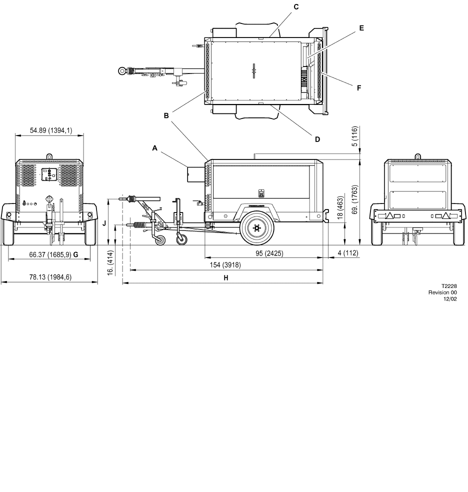
MANUFACTURED IN EUROPE
FRONT VIEW SIDE VIEW
REAR VIEW
TOP VIEW
7/120 9/110 10/105 14/85
P425AWIR XP375AWIR HP375AWIR
VHP300AWIR
All dimensions in inches(mm)
AInstrument panel access door
BPackage air inlet
CAccess items:
Separator element & fill
Compressor oil filter
Fuel filters
Dipstick
Engine oil fill
Coolant bottle fill
DAccess items:
Fuel fill
Engine oil filter
Fuel filter
Engine and compressor air filter
EAccess items:
Radiator fill
FPackage air outlet
GTrack width
HVariable height drawbar
162 (4114) minimum / 168 (4277) maximum
JVariable height drawbar
17 (420) minimum / 35 (880) maximum
17 7/120 (P425AWIR), 9/110 (XP375AWIR), 10/105 (HP375AWIR), 14/85 (VHP300AWIR),
7/170 (P600WIR), 10/125 (HP450WIR), 14/115 (VHP400WIR)
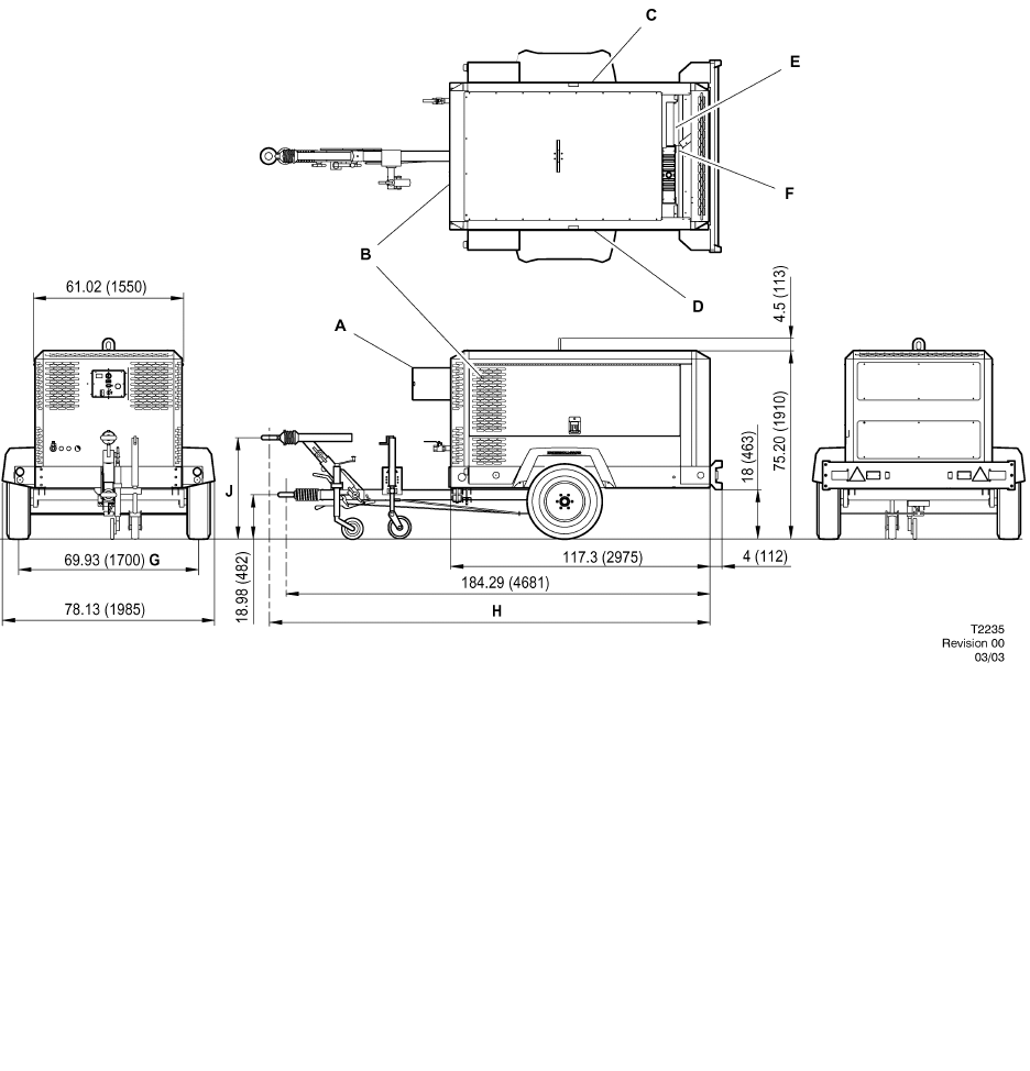
MANUFACTURED IN EUROPE
FRONT VIEW SIDE VIEW
REAR VIEW
TOP VIEW
7/170 10/125 14/115
P600WIR HP450WIR VHP400WIR
All dimensions in inches(mm)
AInstrument panel access door
BPackage air inlet
CAccess items:
Separator element & fill
Compressor oil filter
Fuel filters
Dipstick
Engine oil fill
Coolant bottle fill
DAccess items:
Fuel fill
Engine oil filter
Fuel filter
Engine and compressor air filter
EAccess items:
Radiator fill
FPackage air outlet
GTrack width
HVariable height drawbar
184.29 (4681) minimum / 189.21 (4806) maximum
JVariable height drawbar
18.98 (482) minimum / 37.17 (944) maximum

18
7/120 (P425AWIR), 9/110 (XP375AWIR), 10/105 (HP375AWIR), 14/85 (VHP300AWIR),
7/170 (P600WIR), 10/125 (HP450WIR), 14/115 (VHP400WIR)
COMPRESSOR
Actual free air delivery. 12,0 m3 min–1 (425 CFM)
(7/120) (P425AWIR)
Actual free air delivery. 10,5 m3 min–1 (375 CFM)
(9/110) (XP375AWIR)
Actual free air delivery. 10,5 m3 min–1 (375 CFM)
(10/105) (HP375AWIR)
Actual free air delivery. 8,5 m3 min–1 (300 CFM)
(14/85) (VHP300AWIR)
Actual free air delivery. 17,0 m3 min–1 (600 CFM)
(7/170) (P600WIR)
Actual free air delivery. 12,8 m3 min–1 (450 CFM)
(10/125) (HP450WIR)
Actual free air delivery. 11,3 m3 min–1 (400 CFM)
(14/115) (VHP400WIR)
Normal operating discharge pressure. 7 bar (100 PSI)
(7/120) (P425AWIR)
Normal operating discharge pressure. 8,6 bar (125 PSI)
(9/110) (XP375AWIR)
Normal operating discharge pressure. 10,3 bar (150 PSI)
(10/105) (HP375AWIR)
Normal operating discharge pressure. 14 bar (200 PSI)
(14/85) (VHP300AWIR)
Normal operating discharge pressure. 7 bar (100 PSI)
(7/170) (P600WIR)
Normal operating discharge pressure. 10,3 bar (150 PSI)
(10/125) (HP450WIR)
Normal operating discharge pressure. 14 bar (200 PSI)
(14/115) (VHP400WIR)
Maximum allowable pressure. 8,6 bar (125 PSI)
(7/120) (P425AWIR)
Maximum allowable pressure. 10.3 bar (150 PSI)
(9/110) (XP375AWIR)
Maximum allowable pressure. 12.1 bar (175 PSI)
(10/105) (HP375AWIR)
Maximum allowable pressure. 15.5 bar (225 PSI)
(14/85) (VHP300AWIR)
Maximum allowable pressure. 8,6 bar (125 PSI)
(7/170) (P600WIR)
Maximum allowable pressure. 12.1 bar (175 PSI)
(10/125) (HP450WIR)
Maximum allowable pressure. 15.5 bar (225 PSI)
(14/115) (VHP400WIR)
Safety valve setting. 10 bar (150 PSI)
(7/120) (P425AWIR)
Safety valve setting. 10 bar (200 PSI)
(9/110) (XP375AWIR)
Safety valve setting. 14 bar (200 PSI)
(10/105) (HP375AWIR)
Safety valve setting. 17 bar ( 250 PSI)
(14/85) (VHP300AWIR)
Safety valve setting. 10 bar (150 PSI)
(7/170) (P600WIR)
Safety valve setting. 14 bar (200 PSI)
(10/125) (HP450WIR)
Safety valve setting. 17 bar ( 250 PSI)
(14/115) (VHP400WIR)
Maximum pressure ratio (absolute). 7 ,9 : 1
(7/120) (P425AWIR)
Maximum pressure ratio (absolute). 9, 6 : 1
(9/110) (XP375AWIR)
Maximum pressure ratio (absolute). 11, 3 : 1
(10/105) (HP375AWIR)
Maximum pressure ratio (absolute). 14, 8 : 1
(14/85) (VHP300AWIR)
Maximum pressure ratio (absolute). 7 ,9 : 1
(7/170) (P600WIR)
Maximum pressure ratio (absolute). 11, 3 : 1
(10/125) (HP450WIR)
Maximum pressure ratio (absolute). 14, 8 : 1
(14/115) (VHP400WIR)
Operating ambient temperature.
Whisperized –12C TO +49C (1OF TO 120F)
Maximum discharge temperature. 120C (248F)
Cooling system. Oil injection
Oil capacity. 36 litres ( 9.5 GAL)
Maximum oil system temperature. 120C (248F)
Maximum oil system pressure. 8,6 bar (125 PSI)
(7/120) (P425AWIR)
Maximum oil system pressure. 10.3 bar (150 PSI)
(9/110) (XP375AWIR)
Maximum oil system pressure. 12.1 bar (175 PSI)
(10/105) (HP375AWIR)
Maximum oil system pressure. 15.5 bar (225 PSI)
(14/85) (VHP300AWIR)
Maximum oil system pressure. 8,6 bar (125 PSI)
(7/170) (P600WIR)
Maximum oil system pressure. 12.1 bar (175 PSI)
(10/125) (HP450WIR)
Maximum oil system pressure. 15.5 bar (225 PSI)
(14/115) (VHP400WIR)
LUBRICATING OIL SPECIFICATION
(for the specified ambient temperatures).
ABOVE –23C(–9_F)
Recommended: Pro–Tec
Approved: SAE 10W, API CF–4/CG–4

19 7/120 (P425AWIR), 9/110 (XP375AWIR), 10/105 (HP375AWIR), 14/85 (VHP300AWIR),
7/170 (P600WIR), 10/125 (HP450WIR), 14/115 (VHP400WIR)
BELOW –23C(–9_F)
Mandatory: IR Performance 500
Ingersoll–Rand Pro–TecTM compressor fluid is
factory–fitted, for use at all ambient temperatures above
–23C(–9F).
NOTE: Warranty may be extended only by continuous use of
Pro–Tec and Ingersoll–Rand oil filters and separators.
No other oil/fluids are compatible with Pro–TecTM
No other oils/fluids should be mixed with Pro–TecTM
because the resulting mixture could cause damage to the
airend.
In the event that Pro–TecTM is not available and / or the end
user needs to use an approved single grade engine oil, the
complete system including separator / receiver, cooler and
pipework must be flushed clear of the first fill fluid and new
Ingersoll–Rand oil filters installed.
When this has been completed, the following oils are approved:
a) for ambient temperatures above –23C(–9F),
SAE 10W, API CF–4/CG–4
b) for ambient temperatures below –23C(–9F),
I–R Performance 500 only.
Safety data sheets can be obtained on request from the
lubricant supplier.
For temperatures outside the specified ambient range,
consult Ingersoll–Rand.
ENGINE
7/120 (P425WIR), 9/110 (XP375AWIR),
10/105 (HP375AWIR), 14/85 (VHP300AWIR)
Type/model. Ingersoll–Rand
Number of cylinders. 4
Oil capacity. 13.2 litres ( 3.5 GAL)
Speed at full load. 2400 revs
min–1(RPM)
Speed at idle. 1400 revs min–1
(RPM)
Electrical system. 24V negative earth
Power available at 2400 revs min–193 kW (125 HP)
Fuel tank capacity 219.5 litres ( 58
GAL)
Oil specification Refer engine section
Coolant capacity 17 litres(4.5 GAL)
ENGINE
7/170 (P600WIR), 10/125 (HP450WIR), 14/115 (VHP400WIR)
Type/model. Ingersoll–Rand
Number of cylinders. 6
Oil capacity. 22.1 litres (5.75 GAL)
Speed at full load. 2400 revs min–1
(RPM)
Speed at idle. 1400 revs min–1
(RPM)
Electrical system. 24V negative earth
Power available at 2400 revs min–1126.8 kW (170 HP)
Fuel tank capacity 276 litres
(73 GAL)
Oil specification Refer engine section
Coolant capacity 28.4 litres(7.5 GAL)
SOUND LEVEL DATA (‘W’ model)
A) To Pneurop code PN8NTC2.
Equivalent continuous sound pressure level.*
. Rated load 85 dB(A)
(Operator position :–1m from machine)
Sound power level (84/533/EEC) 101 dB(A)
B) In compliance with 86/188/EEC.
Average sound pressure level at 10m
to 79/113/EEC.* 73 dB(A)
(*Machine only :– at maximum load in open site conditions)
C) EPA Noise 76 dB(A)
FIXED HEIGHT RUNNING GEAR (European Only)
Braked version
(7/120) ( 9/110), (10/105), (14/85)
Shipping weight. 1935kg (4266Lbs)
Maximum weight. 2200kg (4850Lbs)
Maximum horizontal towing force. 2009kg (4429Lbs)
Maximum vertical coupling load
(nose weight). 100 kgf (220 Lbs)
FIXED HEIGHT RUNNING GEAR (European Only)
Braked version
(7/170), (10/125), (14/115)
Shipping weight. 2364kg (5200Lbs)
Maximum weight. 2598kg (5715Lbs)
Maximum horizontal towing force. 2700kg (5940Lbs)
Maximum vertical coupling load
(nose weight). 150 kgf (330 Lbs)

20
7/120 (P425AWIR), 9/110 (XP375AWIR), 10/105 (HP375AWIR), 14/85 (VHP300AWIR),
7/170 (P600WIR), 10/125 (HP450WIR), 14/115 (VHP400WIR)
VARIABLE HEIGHT RUNNING GEAR (European Only)
Braked version
(7/120) ( 9/110), (10/105), (14/85)
Shipping weight. 1965kg (4331Lbs)
Maximum weight. 2200kg (4850Lbs)
Maximum horizontal towing force. 2009kg (4429Lbs)
Maximum vertical coupling load
(nose weight). 100 kgf (220 Lbs)
VARIABLE HEIGHT RUNNING GEAR (European Only)
Braked version
(7/170), (10/125), (14/115)
Shipping weight. 2400kg (5280Lbs)
Maximum weight. 2636kg (5800Lbs)
Maximum horizontal towing force. 2900kg (5940Lbs)
Maximum vertical coupling load
(nose weight). 150 kgf (330 Lbs)
WHEELS AND TYRES (European) – 7/120, 9/110, 10/105,
14/85
Number of wheels. 2 x 5.5
Tyre size. 205/75 R16
Tyre pressure. 4.5 bar (65 psi)
WHEELS AND TYRES (European) – 7/170, 10/125, 14/115
Number of wheels. 2 x 6.0
Tyre size. 205/75 P17.5
Tyre pressure. 6.5 bar (94 psi)
Further information may be obtained by request through
Ingersoll–Rand customer services department.
COMMISSIONING
Upon receipt of the unit, and prior to putting it into service, it
is important to adhere strictly to the instructions given below in
PRIOR TO STARTING.
Ensure that the operator reads and understands the decals
and consults the manuals before maintenance or operation.
Ensure that the position of the emergency stop device is
known and recognised by its markings. Ensure that it is
functioning correctly and that the method of operation is known.
Running gear drawbar (European Area) – Machines are
shipped to some areas with the drawbar removed. Fitting
involves four nuts / bolts to secure the drawbar to the axle and
two bolts to fit the drawbar to the front of the machine with the
saddle and spacer block.
Support the front of the machine, fit the wheel chocks to stop
the machine moving and attach the drawbar. Refer to the torque
value table in the MAINTENANCE section of this manual for the
correct torque values.
CAUTION:
This is a safety critical procedure. Double check the torque
settings after assembly
Fit the propstand and coupling. Remove the supports and
set the machine level.
Before towing the unit, ensure that the tyre pressures are
correct (refer to the GENERAL INFORMATION section of this
manual) and that the handbrake is functioning correctly (refer to
the MAINTENANCE section of this manual). Before towing the
unit during the hours of darkness, ensure that the lights are
functioning correctly (where fitted).
Ensure that all transport and packing materials are
discarded.
Ensure that the correct fork lift truck slots or marked lifting /
tie down points are used whenever the machine is lifted or
transported.
When selecting the working position of the machine ensure
that there is sufficient clearance for ventilation and exhaust
requirements, observing any specified minimum dimensions (to
walls, floors etc.).
Adequate clearance needs to be allowed around and above
the machine to permit safe access for specified maintenance
tasks.
Ensure that the machine is positioned securely and on a
stable foundation. Any risk of movement should be removed by
suitable means, especially to avoid strain on any rigid discharge
piping.
Attach the battery cables to the battery(s) ensuring that they
are tightened securely. Attach the negative cable before
attaching the positive cable.
WARNING: All air pressure equipment installed in or
connected to the machine must have safe working
pressure ratings of at least the machine rated pressure,
and materials compatible with the compressor lubricant
(refer to the GENERAL INFORMATION section).
WARNING: If more than one compressor is connected to
one common downstream plant, effective check valves and
isolation valves must be fitted and controlled by work
procedures, so that one machine cannot accidently be
pressurised / over pressurised by another.
WARNING: If flexible discharge hoses are to carry more
than 7 bar pressure then it is recommended that safety
retaining wires are used on the hoses.
21 7/120 (P425AWIR), 9/110 (XP375AWIR), 10/105 (HP375AWIR), 14/85 (VHP300AWIR),
7/170 (P600WIR), 10/125 (HP450WIR), 14/115 (VHP400WIR)
OPERATING INSTRUCTIONS
PRIOR TO STARTING
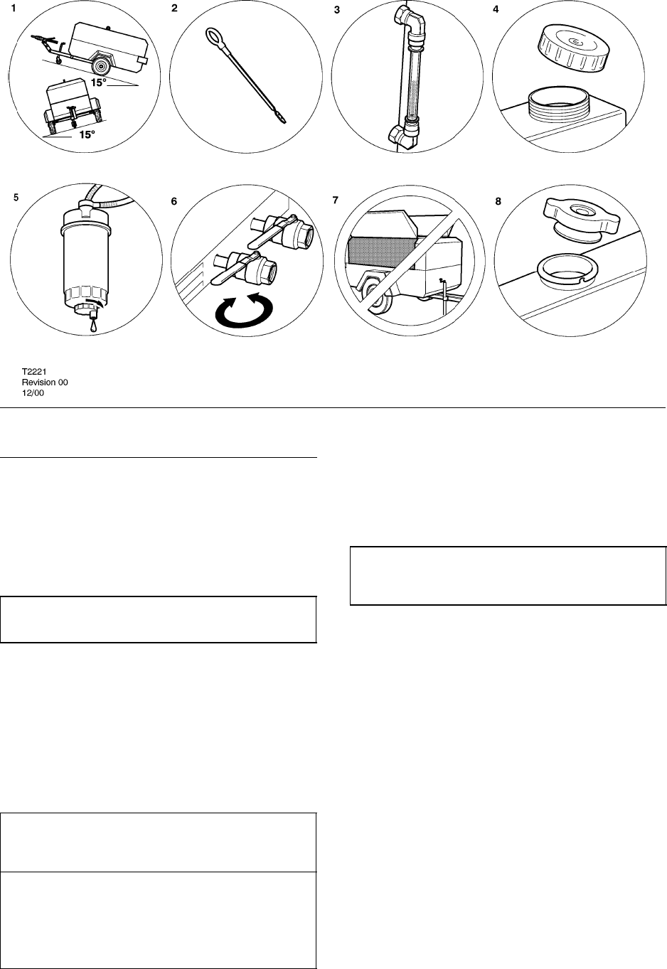
1. Place the unit in a position that is as level as possible. The
design of the unit permits a 15 degree lengthways and sideways
limit on out of level operation. It is the engine, not the
compressor, that is the limiting factor.
When the unit has to be operated out of level, it is important
to keep the engine oil level near the high level mark (with the unit
level).
CAUTION: Do not overfill either the engine or the compressor
with oil.
2. Check the engine lubrication oil in accordance with the
operating instructions in the Engine Operator’s Manual.
3. Check the compressor oil level in the sight glass located on
the separator tank.
4. Check the diesel fuel level. A good rule is to top up at the end
of each working day. This prevents condensation from
occurring in the tank.
CAUTION: Use only a No. 2–D diesel fuel oil with a minimum
octane number of 45 and a sulphur content not greater than
0,5%.
CAUTION: When refuelling:–
.switch off the engine.
.do not smoke.
.extinguish all naked lights.
.do not allow the fuel to come into contact with hot surfaces.
.wear personal protective equipment.
5. Drain the fuel filter water separator of water, ensuring that
any released fuel is safely contained.
6. Open the service valve(s) to ensure that all pressure is
relieved from the system. Close the service valve(s).
7. CAUTION: Do not operate the machine with the
canopy/doors in the open position as this may cause
overheating and operators to be exposed to high noise levels.
8. Check the radiator coolant level (with the unit level).
Check the air restriction indicator(s). Refer to the
MAINTENANCE section of this manual.
When starting or operating the machine in temperatures
below or approaching 0C, ensure that the operation of the
regulation system, the unloader valve, the safety valve, and the
engine are not impaired by ice or snow, and that all inlet and
outlet pipes and ducts are clear of ice and snow.
22
7/120 (P425AWIR), 9/110 (XP375AWIR), 10/105 (HP375AWIR), 14/85 (VHP300AWIR),
7/170 (P600WIR), 10/125 (HP450WIR), 14/115 (VHP400WIR)
84910
11 12
1
35
13
6
714
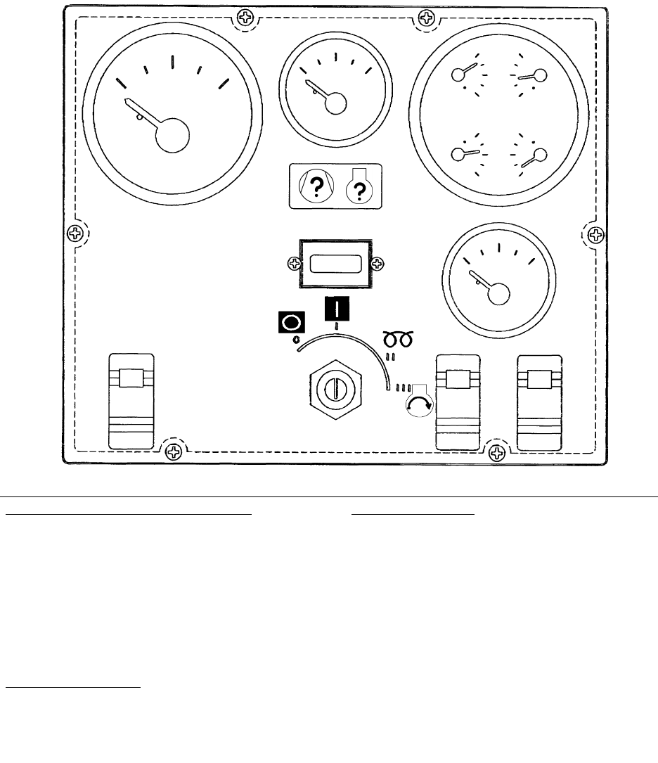
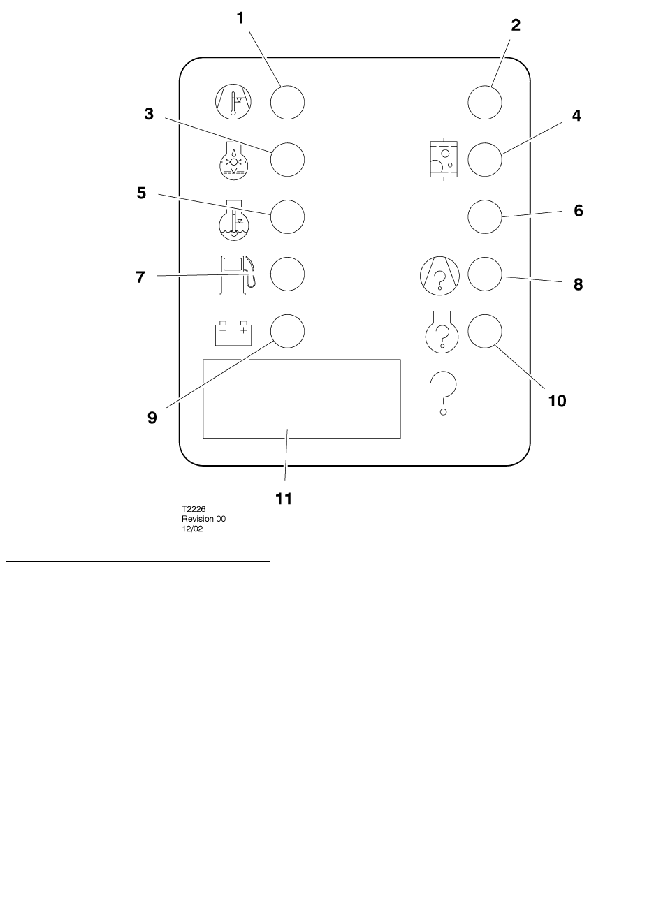
Control Panel
2
DIAGNOSTIC/AUTO SHUTDOWN (STANDARD)
1. Compressor fault – Needs attention. See Wedge
diagnostic panel for more detail.
2. Engine Fault – Needs attention. See Wedge diagnostic
panel for more detail.
3. Hourmeter – Records running time for maintenance.
4. Compressor Discharge Pressure Gauge – Indicates
pressure in receiver tank, psi (kPa).
5. Fuel Level Gauge – Indicates amount of fuel in tank.
CONTROLS (STANDARD)
6. Power Switch – Flip “ON” to activate systems prior to
Starting. Flip “OFF” to stop engine.
7. Service Air Switch – After warm–up, PUSH. Provides full
air pressure at the service outlet.
OPTIONAL CONTROLS
8. Engine Speed Gauge – Indicates engine speed.
9. Discharge Air Temp. Gauge – Indicates in F and C.
Normal operating range: 185F/85C to 248F /120C.
10.Engine Oil Pressure Gauge – Indicates engine oil pressure
(psi (kPa).
11.Engine Water Temp Gauge – Indicates coolant
temperature, with normal operating range from 180F/82C to
210F /99C.
12.Voltmeter – Indicates battery condition.
13.Spare
14.Wait To Start Lamp.
23 7/120 (P425AWIR), 9/110 (XP375AWIR), 10/105 (HP375AWIR), 14/85 (VHP300AWIR),
7/170 (P600WIR), 10/125 (HP450WIR), 14/115 (VHP400WIR)
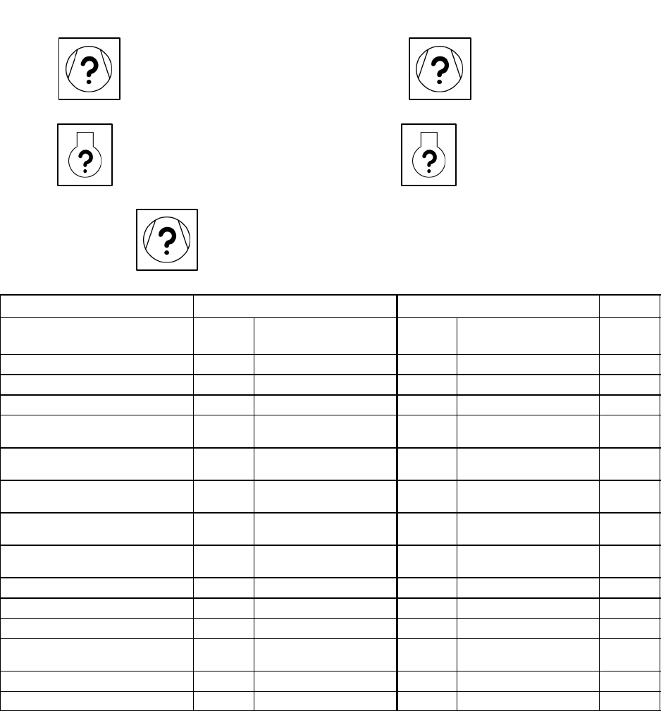
WEDGE DIAGNOSTIC DISPLAY PANEL.
The Wedge diagnostic display panel is arranged
as shown above. A description of each diagnostic
indicator is as follows.
1. High Compressor Temp: Fault indicator
lamp. Indicates shutdown due to high
compressor temperature.
2. Spare
3. Low Engine Oil Pressure: Fault indicator
lamp. Indicates shutdown due to low engine oil
pressure.
4. Restricted Air Filter: Alarm indicator lamp.
Indicates engine/compressor air inlet filters
need service.
5. High Engine Coolant Temp: Fault indicator
lamp. Indicates shutdown due to high engine
water temperature.
6. Spare
7. Low Fuel Level: Fault indicator lamp.
Indicates shutdown due to low fuel level. Lamp
blinks at low fuel warning.
8. Compressor Malfunction: Fault indicator
lamp. Indicates shutdown due to compressor
system fault. Refer to Fault Code List.
9. Low Battery Voltage: Alarm indicator lamp.
Indicates battery or charging system requires
service.
10.Engine Malfunction: Engine Fault code.
Refer to service card or engine manual for
codes and service requirements.
11. Malfunction Code (4 Digit): Compressor or
engine fault. Refer to manual for list of codes
and service requirements.
24
7/120 (P425AWIR), 9/110 (XP375AWIR), 10/105 (HP375AWIR), 14/85 (VHP300AWIR),
7/170 (P600WIR), 10/125 (HP450WIR), 14/115 (VHP400WIR)
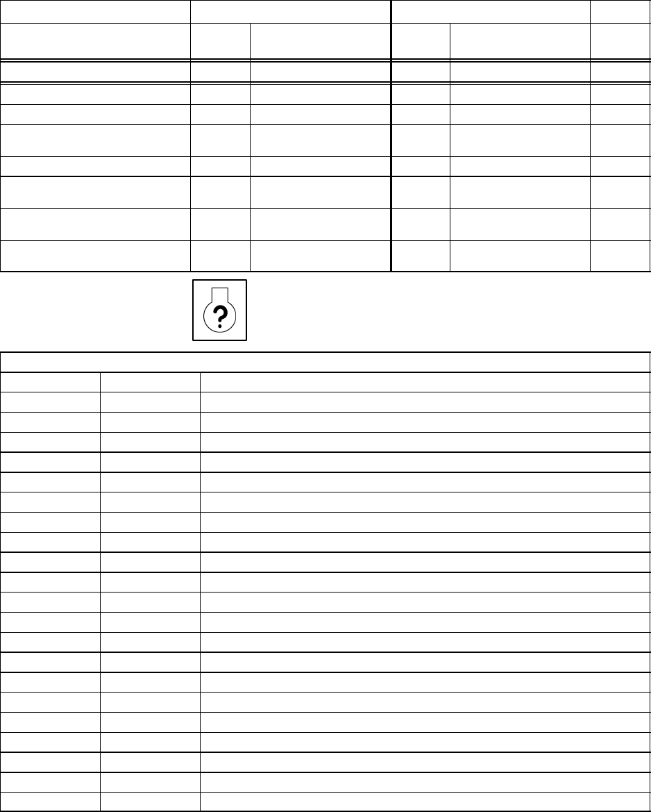
Wedge Diagnostic Display Codes
If the fault indicator lamp is illuminated, refer to the Alert/Shutdown list below.
If the fault indicator lamp is illuminated, refer to the Engine diagnostic list below.
ALERT/SHUTDOWN CONDITIONS Version: 1.40
Alert Shutdown
Condition Code Light (Blinks) Code Light (Steady) Delay
(sec.)
Engine Speed <900 RPM 1CPRSR Malf. 30
Engine Speed >2500 RPM 2CPRSR Malf. 30
Engine Crank Time Exceeded 3CPRSR Malf. 0
Intake Manifold Temperature > 180
deg. F 6CPRSR Malf.
Engine Not Responding To Throttle
Command 10 CPRSR Malf.
Engine Shut Itself Down: reason
unknown 29 CPRSR Malf.
Disch. Temp (RT2)
Sensor Fault 32 CPRSR Malf. 10
Sep. Tank Pressure (PT1)
Sensor Fault 33 CPRSR Malf.
Separator Tank Temp.> 247 deg.F) 50 CPRSR Malf. 3
Machine ID Not Valid 51 CPRSR Malf. 0
Sep. Tank Temp. (RT1) Sensor Fault 53 CPRSR Malf. 10
Reg. System Pressure (PT2) Sensor
Fault 54 CPRSR Malf.
Serial Comm. Problem 70 CPRSR Malf.
CAN Bus Problem 71 CPRSR Malf.
25 7/120 (P425AWIR), 9/110 (XP375AWIR), 10/105 (HP375AWIR), 14/85 (VHP300AWIR),
7/170 (P600WIR), 10/125 (HP450WIR), 14/115 (VHP400WIR)
Alert Shutdown
Condition Code Light (Blinks) Code Light (Steady) Delay
(sec.)
Dedicated Lights:
Low Fuel Level Fuel Level Fuel Level 3
Air Filter Restriction (Option) Soiled Filter
Low Battery Voltage Battery Charging
Condition
Engine Oil Pressure < 18 PSI Low Engine Oil Pressure
Engine Coolant Temperature
>= 215 deg. F High Engine Temp.
Engine Coolant Temperature
>= 220 deg. F High Comp. Temp. 10
High Discharge Temp.
(RT2 > 247 deg. F) High Comp. Temp. 3
ENGINE DIAGNOSTIC CODES
Listing of Diagnostic Trouble Codes (DTCs)
Displayed Code FMI* Definition
28 3 Analog Throttle (B) Input Voltage High
4Analog Throttle (B) Input Voltage Low
29 3 Analog Throttle (A) Input Voltage High
4Analog Throttle (A) Input Voltage Low
91 3 Multi–state Throttle Input Voltage High
4Multi–state Throttle Input Voltage Low
100 1 Engine Oil Pressure Extremely Low
3Engine Oil Pressure Input Voltage High
4Engine Oil Pressure Input Voltage Low
18 Engine Oil Pressure Moderately Low
105 3 Manifold Air Temperature Input Voltage High
4Manifold Air Temperature Input Voltage Low
16 Manifold Air Temperature Moderately High
110 0Engine Coolant Temperature High Most Severe
3Engine Coolant Temperature Input Voltage High
4Engine Coolant Temperature Input Voltage Low
15 Engine Coolant Temperature High Least Severe
16 Engine Coolant Temperature High Moderately Severe
158 17 ECU Power Down Error
174 3 Fuel Temperature Input Voltage High
4Fuel Temperature Input Voltage Low

26
7/120 (P425AWIR), 9/110 (XP375AWIR), 10/105 (HP375AWIR), 14/85 (VHP300AWIR),
7/170 (P600WIR), 10/125 (HP450WIR), 14/115 (VHP400WIR)
Listing of Diagnostic Trouble Codes (DTCs)
Displayed Code FMI* Definition
16 Fuel Temperature Moderately High
190 0 Engine Overspeed Extreme
16 Engine Overspeed Moderate
620 3 Sensor Supply Voltage High
4Sensor Supply Voltage Low
637 2 Crankshaft Position Input Noise
10 Crankshaft Position Input Pattern Error
970 31 Auxiliary Engine Shutdown Switch Active
971 31 External Engine Derate Switch Active
1076 0 Pump Control Valve Closure Too Long
1Pump Control Valve Closure Too Short
5Pump Solenoid Circuit Open
6Pump Soleniod Circuit Severely Shorted
7Pump Control Valve Closure Not Detected
10 Pump Solenoid Circuit Moderately Shorted
1109 31 Engine Shutdown Warning
1110 31 Engine Shutdown
1569 31 Fuel Derate
2000 6 Internal ECU Failure
* FMI (Failure Mode Indicator) – Requires engine diagnostic tool to display.
27 7/120 (P425AWIR), 9/110 (XP375AWIR), 10/105 (HP375AWIR), 14/85 (VHP300AWIR),
7/170 (P600WIR), 10/125 (HP450WIR), 14/115 (VHP400WIR)
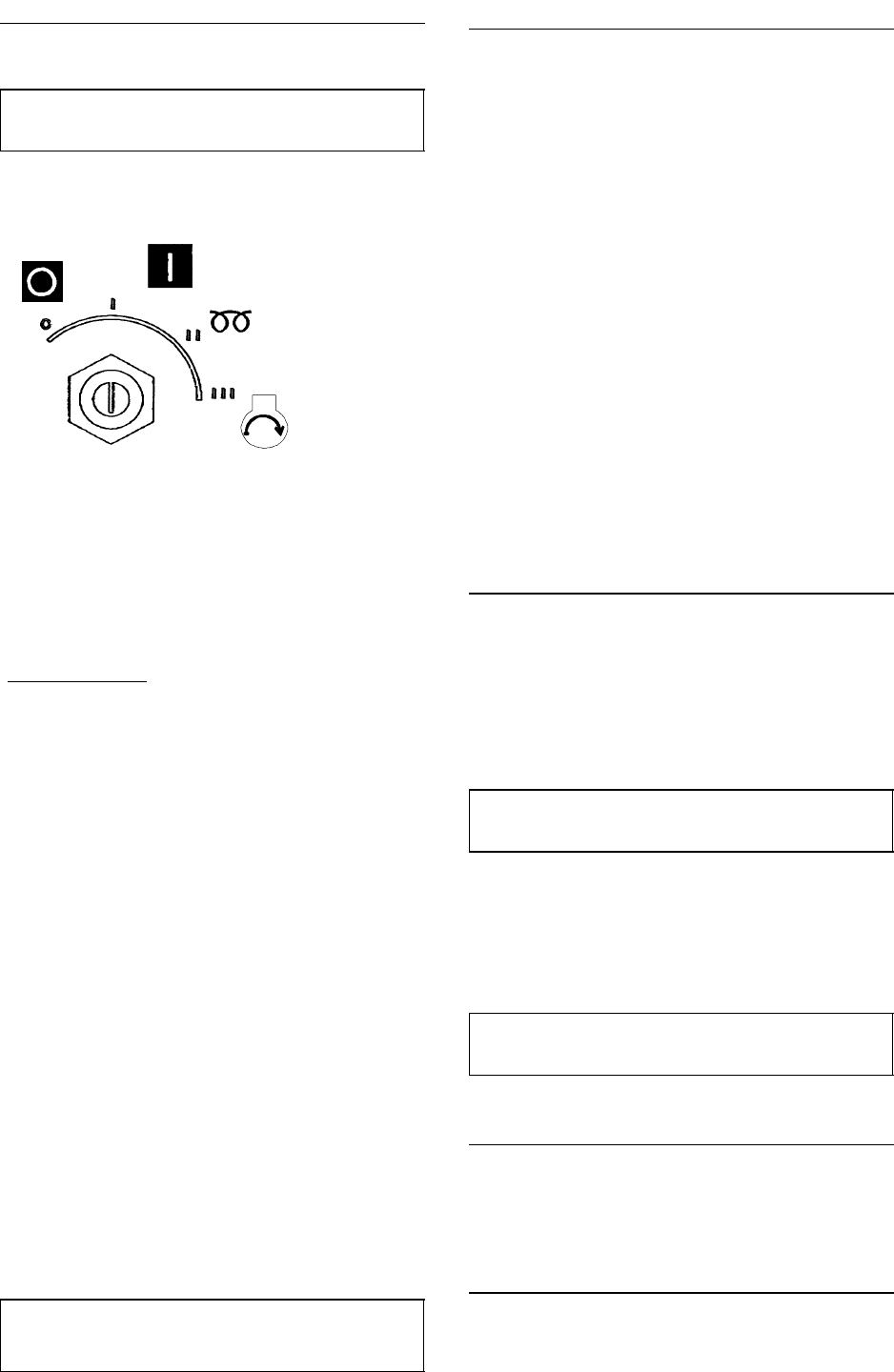
STARTING THE MACHINE
WARNING: Under no circumstances should volatile liquids
such as Ether be used for starting this machine.
1
3
2
All normal starting functions are incorporated in the key
operated switch.
.Turn the key switch to position 1. The engine fault and
compressor fault lamps will flash..
Wait To Start Lamp.
.Turn the key switch to position 1 until the Wait To Start Lamp.
(14) extinguishes.
.Turn the key switch to crank position (3) (engine start
position)
.NOTE: Position (2) not used on AWIR models.
.Release to position (1) when engine starts. The engine will
now be running at a reduced speed.
At temperatures below 0C or if there is difficulty starting first
time:
. Open the service valve fully, with no hose connected.
. Complete starting sequence above.
. Close service valve as soon as engine runs freely.
. Do not allow machine to run for long periods with service
valve open.
. Allow the engine to reach operating temperature.
. At this point in the operation of the machine it is safe to apply
full load to the engine.
NOTE: Wear hearing protection at all times when the engine is
started with the service valve open and air is flowing from the
valve.
PUSH AFTER WARM UP
NOTE: In order to allow the machine to start at a reduced load,
a valve, which is operated by a button located on the instrument
panel, is incorporated in the regulation system. (The valve
automatically returns to the start position when the machine is
switched off and air pressure relieved from the system).
. Allow the engine to reach its operating temperature – then
press the button (7).
. At this point in the operation of the machine it is safe to apply
full load to the engine.
DUAL PRESSURE WHEN FITTED
Machines which operate in excess of 7 bar (100 psi) can
optionally be fitted with a dual pressure switch inside the unit.
This switch selects between 7 bar (100 psi) and the machine
rated pressure, cfm remains nominally constant.
Starting and stopping are unaffected by the selection and during
normal running the selector switch may be safely operated.
Precaution must be taken to ensure that downstream
equipment is rated to suit the available pressure.
The pressure gauge indicates which setting has been selected.
STOPPING THE MACHINE
.Close the service valve.
.Allow the machine to run unloaded for a short period of time
to reduce the engine temperature.
.Turn the start switch to the 0 (off) position.
NOTE: As soon as the engine stops, the automatic blowdown
valve will relieve all pressure from the system.
If the automatic blowdown valve fails to operate, then
pressure must be relieved from the system by means of the
service valve(s).
CAUTION: Never allow the machine to stand idle with pressure
in the system.
EMERGENCY STOPPING
In the event that the unit has to be stopped in an emergency,
TURN THE KEY SWITCH LOCATED ON THE INSTRUMENT
PANEL TO THE 0 (OFF) POSITION.
RE–STARTING AFTER AN EMERGENCY
If the machine has been switched off because of a machine
malfunction, then identify and correct the fault before attempting
to re–start.

28
7/120 (P425AWIR), 9/110 (XP375AWIR), 10/105 (HP375AWIR), 14/85 (VHP300AWIR),
7/170 (P600WIR), 10/125 (HP450WIR), 14/115 (VHP400WIR)
If the machine has been switched off for reasons of safety,
then ensure that the machine can be operated safely before
re–starting.
Refer to the PRIOR TO STARTING and STARTING THE
UNIT instructions earlier in this section before re–starting the
machine.
MONITORING DURING OPERATION
Should any of the safety shut-down conditions occur, the unit
will stop.
Refer to the Wedge diagnostic display codes table for a
listing of shutdown conditions.
CAUTiON: To ensure an adequate flow of oil to the compressor
at low temperature, never allow the discharge pressure to fall
below 3,5 bar (50 psi)
DECOMMISSIONING
When the machine is to be permanently decommissioned or
dismantled, it is important to ensure that all hazard risks are
either eliminated or notified to the recipient of the machine. In
particular:–
. Do not destroy batteries or components containing asbestos
without containing the materials safely.
. Do not dispose of any pressure vessel that is not clearly
marked with its relevant data plate information or rendered
unusable by drilling, cutting etc.
. Do not allow lubricants or coolants to be released into land
surfaces or drains.
. Do not dispose of a complete machine without
documentation relating to instructions for its use.

29 7/120 (P425AWIR), 9/110 (XP375AWIR), 10/105 (HP375AWIR), 14/85 (VHP300AWIR),
7/170 (P600WIR), 10/125 (HP450WIR), 14/115 (VHP400WIR)
ENGINE
Engine Serial Number Plate
Each engine has a 13–digit engine serial
number.
The engine’s serial number plate is located on
the right–hand side of cylinder block behind the
fuel filter.
Fuels, Lubricants, and Coolant
Diesel Fuel
Consult your local fuel distributor for properties
of the diesel fuel available in your area.
In general, diesel fuels are blended to satisfy
the low temperature requirements of the
geographical area in which they are marketed.
Diesel fuels specified to EN 590 or ASTM D975
are recommended.
Required fuel properties
In all cases, the fuel must meet the following
properties:
Cetane number of 45 minimum. Cetane
number greater than 50 is preferred, especially
for temperatures below –20C (–4F) or
elevations above 1500 m (5000 ft).
Cold Filter Plugging Point (CFPP) below the
expected low temperature OR Cloud Point at
least 5C (9F) below the expected low
temperature.
Fuel lubricity should pass a minimum load
level of 3100 grams as measured by ASTM
D6078 or, maximum scar diameter of 0.45 mm
as measured by ASTM D6079.
Sulfur content:
• Diesel fuel quality and fuel sulfur content must
comply with all existing regulations for the area
in which the engine operates.
• Sulfur content less than 0.05% (500 ppm) is
preferred.
• If diesel fuel with sulfur content greater than
0.05% (500 ppm) is used, crankcase oil service
intervals may be affected. (See
recommendation for Diesel Engine Oil.)
• DO NOT use diesel fuel with sulfur content
greater than 1.0%.
IMPORTANT: DO NOT mix used engine oil or
any other type of lubricating oil with diesel
fuel.
Bio–Diesel Fuel
Bio–diesel fuels may be used ONLY if the
bio–diesel fuel properties meet the latest edition
of ASTM PS121, DIN 51606 or equivalent
specification.
It has been found that bio–diesel fuels may
improve lubricity in concentrations up to a 5%
blend in petroleum diesel fuel.
When using a blend of bio–diesel fuel, the
engine oil level must be check daily when the air
temperature is –10C (14F) or lower. If the oil
becomes diluted with fuel, shorten oil change
intervals accordingly.
IMPORTANT: Raw pressed vegetable oils
are NOT acceptable for use for fuel in any
concentration.
These oils do not burn completely, and will
cause engine failure by leaving deposits on
injectors and in the combustion chamber.
Handing and Storing Bio–Diesel Fuel
WARNING: Handle fuel carefully. Do not fill
the fuel tank when engine is running.
DO NOT smoke while you fill the fuel tank or
service the fuel system.
Fill the fuel tank at the end of each day’s
operation to prevent water condensation and
freezing during cold weather.
Keep all storage tanks as full as practicable to
minimize condensation.
Ensure that all fuel tank caps and covers are
installed properly to prevent moisture from
entering.
Monitor water content of the fuel regularly.
Fuel filter may require more frequent
replacement due to premature plugging.
Check engine oil level daily prior to starting
engine. A rising oil level may indicate fuel
dilution of the engine oil.
When fuel is stored for an extended period or if
there is a slow turnover of fuel, add a fuel
conditioner to stabilize the fuel and prevent
water condensation. Contact your fuel supplier
for recommendations.
Diesel Fuel Storage
WARNING: Handle fuel carefully. Do not fill
the fuel tank when engine is running.
DO NOT smoke while you fill the fuel tank or
service the fuel system.
Fill the fuel tank at the end of each day’s
operation to prevent water condensation and
freezing during cold weather.

30
7/120 (P425AWIR), 9/110 (XP375AWIR), 10/105 (HP375AWIR), 14/85 (VHP300AWIR),
7/170 (P600WIR), 10/125 (HP450WIR), 14/115 (VHP400WIR)
IMPORTANT: DO NOT store diesel fuel in
galvanized containers. Diesel fuel stored in
galvanized containers reacts with zinc
coating on container to form zinc flakes. If
fuel contains water, a zinc gel will also form.
The gel and flakes will quickly plug fuel
filters, damage injection nozzles and
injection pump.
DO NOT use brass–coated containers for
fuel storage. Brass is an alloy of copper and
zinc.
Store diesel fuel in plastic, aluminum, and steel
containers specially coated for diesel fuel
storage.
Avoid storing fuel over long periods of time. If
fuel is stored for more than a month prior to
use, or there is a slow turnover in fuel tank or
supply tank, add a fuel conditioner to stabilize
the fuel, prevent water condensation.
Minimizing the Effect of Cold Weather on
Diesel Engines
Ingersoll–Rand diesel engines are designed to
operate effectively in cold weather.
See your authorized engine distributor or
servicing dealer for additional information and
availability of cold weather aids.
Use Grade No. 1–D Fuel
When temperatures fall below 5C (40F),
Grade No. 1–D fuel is best suited for cold
weather operation.
Diesel Fuel Additive
IMPORTANT: Treat fuel when outside
temperature drops below 0_C (32_F). For
best results, use with untreated fuel. Follow
all recommended instructions on label.
Use a fuel conditioner (Winter) to treat fuel
during the cold weather season. Winter
formulation is a combination diesel fuel
conditioner and anti–gel additive.
Diesel Engine Oil
Use SAE15W–40 oil viscosity based on the
expected air temperature range of 10F to
122F (–12C–40C) during the period between
oil changes.
The following oil is preferred:
• Pro–Tec Engine Fluid
Other oils may be used if they meet one or
more of the following:
• API Service Classification CI–4
• API Service Classification CH–4
• ACEA Specification E3
• ACEA Specification E4
• ACEA Specification E5
Multi–viscosity diesel engine oils are
preferred.
Diesel fuel quality and sulfur content must
comply with all existing emissions regulations
for the area in which the engine operates.
If diesel fuel with sulfur content greater than
0.05% (500 ppm) is used, reduce the oil and
filter change interval by 100 hours.
If diesel fuel with sulfur content greater than
0.5% (5000 ppm) is used, reduce the service
interval by 50%.
Diesel fuel with sulfur content greater than 1.0%
(10,000 ppm) is not recommended.

31 7/120 (P425AWIR), 9/110 (XP375AWIR), 10/105 (HP375AWIR), 14/85 (VHP300AWIR),
7/170 (P600WIR), 10/125 (HP450WIR), 14/115 (VHP400WIR)
Diesel Engine Coolant
The engine cooling system is filled to provide
year–round protection against corrosion and
cylinder liner pitting, and winter freeze
protection to –37C (–34F).
Low silicate ethylene glycol base coolants for
heavy–duty engines may be used if they meet
one of the following specifications:
• ASTM D5345 (pre–diluted coolant)
• ASTM D4985 (coolant concentrate) in a 40 to
60% mixture of concentrate with quality water.
Coolants meeting these specifications require
use of supplemental coolant additives,
formulated for heavy–duty diesel engines, for
protection against corrosion and cylinder liner
erosion and pitting.
A 50% mixture of ethylene glycol engine coolant
in water provides freeze protection to –37C
(–34F). If protection at lower temperatures is
required, consult your dealer for
recommendations.
Water quality is important to the performance of
the cooling system. Distilled, or de–mineralized
water is recommended for mixing with ethylene
glycol base engine coolant concentrate.
Chlorides <40mg/L
Sulfates <100 mg/L
Total Dissolved Solids <340 mg/L
Total Hardness <170 mg/L
pH 5.5 to 9.0
IMPORTANT: Do not use cooling system
sealing additives or antifreeze that contains
sealing additives.
Supplemental Coolant Additives
The concentration of coolant additives is
gradually depleted during engine operation. For
all recommended coolants, replenish additives
between drain intervals by adding a
supplemental coolant additive every 12 months.
IMPORTANT: Only use coolant additive to
replenish the coolant. Do not use additive
when the entire system is drained and
refilled.
Consult the coolant supplier and follow the
manufacturer’s recommendation for use of
supplemental coolant additives.
The use of non–recommended supplemental
coolant additives may result in additive drop–out
and gelation of the coolant.
Add the manufacturer’s recommended
concentration of supplemental coolant additive.
DO NOT add more than the recommended
amount.
Coolant Drain Intervals
Drain the factory fill engine coolant, flush the
cooling system, and refill with new coolant after
the first 3 years or 3000 hours of operation.
Subsequent drain intervals are determined by
the coolant used for service. At each interval,
drain the coolant, flush the cooling system, and
refill with new coolant.
Operating in Warm Temperature Climates
Ingersoll–Rand engines are designed to operate
using glycol base engine coolants.
Always use a recommended glycol base engine
coolant, even when operating in geographical
areas where freeze protection is not required.
IMPORTANT: Water may be used as coolant
in emergency situations only.
Foaming, hot surface aluminum and iron
corrosion, scaling, and cavitation will occur
when water is used as the coolant, even
when coolant conditioners are added.
Drain cooling system and refill with
recommended glycol base engine coolant
as soon as possible.
Engine Break–In Service
The engine is ready for normal operation.
However, extra care during the first 100 hours
of operation will result in more satisfactory
long–term engine performance and life. DO
NOT exceed 100 hours of operation with
break–in oil.

32
7/120 (P425AWIR), 9/110 (XP375AWIR), 10/105 (HP375AWIR), 14/85 (VHP300AWIR),
7/170 (P600WIR), 10/125 (HP450WIR), 14/115 (VHP400WIR)
Lubrication and Maintenance Service Interval Chart
NOTE: The Service intervals below are for standard industrial engines. See details in Sections which
follow these charts.
Item Lubrication and Maintenance Service Intervals
Check Engine Oil and Coolant Level Daily 500 Hours/12
Months
2000
Hours/24
Months
As Required
Check Fuel Filter/Water Bowl
Check Air Cleaner Dust Unloader Valve & Restriction Indicator
Gauge a
Visual Walk Around Inspection
Service Battery
Check Manual Belt Tensioner and belt wear
Change Engine Oil And Replace Oil Filter
Clean Crankcase Vent Tube
Check Air Intake Hoses, Connections, & System
Replace Fuel Filter Elements—Bleed Fuel System
Check Belt Tensioner and Belt Wear
Check Engine Electrical Ground Connection
Check Cooling System
Pressure Test Cooling System
Flush Cooling System
Test Thermostats
Check and Adjust Engine Valve Clearance
Add Coolant
Replace Air Cleaner Elements
Replace Poly–Vee Belt
A Replace primary air cleaner element when restriction indicator shows a vacuum of 625 mm (25 in.) H2O.
B During engine break–in, change the oil and filter for the first time before 100 hours of operation.
C If the recommended engine oils, or Pro–Tec is not used, the oil and filter change interval is reduced to every 250 hours. If
diesel fuel with a sulfur content greater than 0.05% is used, the oil and filter change interval is also reduced.

33 7/120 (P425AWIR), 9/110 (XP375AWIR), 10/105 (HP375AWIR), 14/85 (VHP300AWIR),
7/170 (P600WIR), 10/125 (HP450WIR), 14/115 (VHP400WIR)
Lubrication & Maintenance/Daily
Daily Pre–starting Checks
Do the following BEFORE STARTING THE
ENGINE for the first time each day:
Check engine oil level on dipstick.
IMPORTANT: DO NOT add makeup oil until
the oil level is BELOW the crosshatch marks
on the dipstick.
IMPORTANT: DO NOT fill above the top mark
on the dipstick. Oil levels anywhere within
crosshatch are considered in the acceptable
range.
To change engine oil and oil filter:
Check the fuel filters for water or debris. If filter
is fitted with a see–through bowl, drain as
needed based on a daily visual inspection.
IMPORTANT: Drain water into a suitable
container and dispose of properly.
a) Loosen drain plugs (A) at bottom of fuel filters
or bowls, if equipped, two or three turns.
b) Loosen air bleed plug (B) two full turns on
fuel filter mounting and drain water from
bottom until fuel starts to drain out.
c) When fuel starts to drain out, tighten drain
plugs securely.
After draining water from the fuel filters, the
filters must be primed by bleeding all air from
the fuel system.
Changing Engine Oil and Replacing Filter
Your engine is equipped with a special oil filter.
NOTE: During break–in, change engine oil and
filter for the first time before 100 hours
maximum of operation.
After break–in, the oil and filter change interval
is 500 hours or every 12 months, whichever
comes first.
NOTE: If diesel fuel with a sulfur content
greater than 0.05% (500 ppm) is used, the oil
and filter change interval is reduced.
To change engine oil and oil filter:
1. Run engine approximately 5 minutes to warm
up oil. Shut engine off.
2. Remove oil pan drain plug.
3. Drain crankcase oil from engine while warm.
4. Turn filter element using a suitable filter
wrench to remove. Discard oil filter element.
Important: Filtration of oils is critical to
proper lubrication. Always change filter
regularly.
5. Apply clean engine oil to the new filter at the
inner and outer seals and to filter threads.
6. Wipe both sealing surfaces of the header
with a clean rag. Ensure dust seal is in place,
replace if damaged.
IMPORTANT: When installing filter element,
HAND TIGHTEN only. A filter wrench may be
used for REMOVAL ONLY.
7. Install and tighten oil filter by hand until firmly
against dust seal. DO NOT apply an extra
3/4 to 1–1/4 turn after gasket contact as done
with standard filters.
8. Tighten drain plug to specifications.
Specification
Oil Pan Drain Plug With Copper Washer—
Torque 70 N•m (52 lb ft)
Oil Pan Drain Plug With O–Ring—
Torque 50 N•m (37 lb ft)
9. Fill engine crankcase with Pro–Tec Engine
Fluid.
To determine the correct oil fill quantity for your
engine, see ENGINE CRANKCASE OIL FILL
QUANTITIES in the Specifications Section of
this manual.
IMPORTANT: Immediately after completing
any oil change, crank engine for 30 seconds
without permitting engine to start. This will
help insure adequate lubrication to engine
components before engine starts.
NOTE: Crankcase oil capacity may vary slightly.
ALWAYS fill crankcase within crosshatch marks
on dipstick. DO NOT overfill.
10. Start engine and run to check for possible
leaks.
11. Stop engine and check oil level after 10
minutes. Oil level reading should be within
crosshatch of dipstick.
Cleaning Crankcase Vent Tube
If you operate the engine in dusty conditions,
clean the tube at shorter intervals.
1. Remove and clean crankcase vent tube.
2. Install the vent tube. Be sure the O–ring fits
correctly in the rocker arm cover for elbow
adapter.
Replacing Fuel Filter Elements

34
7/120 (P425AWIR), 9/110 (XP375AWIR), 10/105 (HP375AWIR), 14/85 (VHP300AWIR),
7/170 (P600WIR), 10/125 (HP450WIR), 14/115 (VHP400WIR)
Engine is equipped with a primary fuel filter (or
pre–filter) with water bowl and a final filter. Both
filters are replaced at the same 500–hour
interval.
CAUTION: Escaping fluid under pressure
can penetrate the skin causing serious
injury. Relieve pressure before
disconnecting fuel or other lines. Tighten all
connections before applying pressure. Keep
hands and body away from pinholes and
nozzles which eject fluids under high
pressure. Use a piece of cardboard or paper
to search for leaks. Do not use your hand.
1. Close fuel shut–off valve, if equipped.
2. Thoroughly clean fuel filter assemblies and
surrounding areas.
3. Disconnect water sensor wiring (if equipped).
4. Loosen drain plugs and drain fuel into a
suitable container.
NOTE: Lifting up on retaining ring as it is
rotated helps to get it past raised locators.
5. Firmly grasp the retaining ring and rotate it
counterclockwise 1/4 turn. Remove ring with
filter element.
6. Inspect filter mounting base for cleanliness.
Clean as required.
NOTE: Raised locators on fuel filter canisters
must be indexed properly with slots in mounting
base forcorrect installation.
7. Install new filter elements onto mounting
bases. Be sure elements are properly
indexed and firmly seated on bases. It may
be necessary to rotate filters for correct
alignment.
If equipped with water separator bowl (E),
remove filter element from separator bowl.
Drain and clean separator bowl. Dry with
compressed air. Install bowl onto new element.
Tighten securely.
8. Align keys on filter element with slots in filter
base.
9. Install retaining ring onto mounting base
making certain dust seal is in place on filter
base. Hand tighten ring (about 1/3 turn) until
it “snaps” into the detent. DO NOT
overtighten retaining ring.
NOTE: The proper installation is indicated when
a ”click” is heard and a release of the retaining
ring is felt. A plug is provided with the new
element for plugging the used element.
10. Reconnect water sensor wiring (if
equipped).
11. Open fuel shut–off valve and bleed the fuel
system.
Checking Belt Tensioner Spring Tension
and Belt Wear (Automatic Tensioner)
Belt drive systems equipped with automatic
(spring) belt tensioners cannot be adjusted or
repaired. The automatic belt tensioner is
designed to maintain proper belt tension over
the life of the belt. If tensioner spring tension is
not within specification, replace tensioner
assembly.
Checking Belt Wear
The belt tensioner is designed to operate within
the limit of arm movement provided by the cast
stops when correct belt length and geometry is
used.
Visually inspect cast stops on belt tensioner
assembly.
If the tensioner stop on swing arm is hitting the
fixed stop, check mounting brackets (alternator,
belt tensioner, idler pulley, etc.) and the belt
length. Replace belt as needed
Checking Tensioner Spring Tension
A belt tension gauge will not give an accurate
measure of the belt tension when automatic
spring tensioner is used. Measure tensioner
spring tension using a torque wrench and
procedure outlined below:
1. Release tension on belt using a breaker bar
and socket on tension arm. Remove belt from
pulleys.
2. Release tension on tension arm and remove
breaker bar.
3. Put a mark on swing arm of tensioner as
shown.
4. Measure 21 mm (0.83 in.) and put a mark on
tensioner mounting base.
5. Install torque wrench so that it is aligned with
centers of pulley and tensioner. Rotate the
swing arm using a torque wrench until marks
are aligned.
6. Record torque wrench measurement and
compare with specification below. Replace
tensioner assembly as required.
Specification
Spring Tension—Torque 18–22 N•m (13–16 lb–ft)
NOTE: Threads on belt tensioner roller cap
screw are LEFT–HAND threads.
Checking Engine Electrical Ground
Connections
Keep all engine ground connections clean and
tight to prevent electrical arcing which can
damage electronic components.

35 7/120 (P425AWIR), 9/110 (XP375AWIR), 10/105 (HP375AWIR), 14/85 (VHP300AWIR),
7/170 (P600WIR), 10/125 (HP450WIR), 14/115 (VHP400WIR)
Replenishing Supplemental Coolant
Additives (SCAs) Between Coolant Changes
NOTE: If system is to be filled with coolant that
does not contain SCAs, the coolant must be
precharged.
Through time and use, the concentration of
coolant additives is gradually depleted during
engine operation. Periodic replenishment of
inhibitors is required. The cooling system must
be recharged with additional supplemental
coolant additives available in the form of liquid
coolant conditioner.
Maintaining the correct coolant conditioner
concentration (SCAs) and freeze point is
essential in your cooling system to protect
against rust, liner pitting and corrosion, and
freeze–ups due to incorrect coolant dilution.
DO NOT mix one brand of SCA with a
different brand.
Recharge the system per instructions printed on
label of the Coolant Conditioner.
IMPORTANT: Always maintain coolant at
correct level and concentration. DO NOT
operate engine without coolant even for a
few minutes.
If frequent coolant makeup is required, the
glycol concentration should be checked to
ensure that the desired freeze point is
maintained. Follow manufacturer’s
instructions provided with Coolant/Battery
Tester.
Add the manufacturer’s recommended
concentration of supplemental coolant additive.
DO NOT add more than the recommended
amount.
The use of non–recommended supplemental
coolant additives may result in additive drop–out
and gelation of the coolant.
If other coolants are used, consult the coolant
supplier and follow the manufacturer’s
recommendation for use of supplemental
coolant additives.
Replacing Fan and Alternator Belts
Refer to CHECKING BELT TENSIONER
SPRING TENSION AND BELT WEAR in
Lubrication and Maintenance/500 Hour/12
Month Section for additional information on the
belt tensioner.
1. Inspect belts for cracks, fraying, or stretched
out areas. Replace if necessary.
2. To replace belt with automatic tensioner,
release tension on belt using a breaker bar
and socket on tension arm.
To replace belt with manual tensioner, release
tension at belt tensioner.
3. Remove poly–vee belt from pulleys and
discard belt.
4. Install new belt, making sure belt is correctly
seated in all pulley grooves. Refer to belt
routing at right for your application.
5. Apply tension to belt with tensioner. Remove
socket.
6. Start engine and check belt alignment.
Bleeding the Fuel System
Bleed the Fuel System (Engines with Electronic
Fuel Systems and Stanadyne DE10 Pump)
CAUTION: Escaping fluid under pressure
can penetrate the skin causing serious
injury. Avoid hazards by relieving pressure
before disconnec ing hydraulic or other
lines. Tighten all connections before
applying pressure. Search for leaks with a
piece of cardboard. Protect hands and body
from high pressure fluids.
Any time the fuel system has been opened up
for service (lines disconnected or filters
removed), it will be necessary to bleed air from
the system.
The fuel system may be bled at one of several
locations. Choose the best location for your
engine/machine application.
1. Loosen the air bleed vent screw two full turns
by hand on fuel filter base.
2. Operate fuel supply pump primer lever (B) or
primer button on fuel filter base (if equipped).
3. Tighten bleed plug securely, continue
operating primer until pumping action is not
felt.
4. Start engine and check for leaks.
If engine will not start, it may be necessary to
bleed air from fuel system at fuel injection pump
or injection nozzles as explained next.
At Fuel Injection Pump
1. Loosen fuel return line at fuel injection pump.
2. Operate fuel supply pump primer lever or
primer button on fuel filter base (if equipped).
3. As soon as fuel flow is free from air bubbles,
tighten fuel return line to specifications.
Primer lever is spring–loaded and will return
to normal position.
Specification
Fuel Injection Pump Return
Line—Torque 27 N•m (20 lb–ft)

36
7/120 (P425AWIR), 9/110 (XP375AWIR), 10/105 (HP375AWIR), 14/85 (VHP300AWIR),
7/170 (P600WIR), 10/125 (HP450WIR), 14/115 (VHP400WIR)
At Fuel Injection Nozzles
IMPORTANT: Always use a backup wrench
when loosening or tightening fuel lines at
nozzles and/or injection pump to avoid
damage.
1. Using two open–end wrenches, loosen two
fuel line connections at injection nozzles.
2. Crank engine over with starter motor for 15
seconds (but do not start engine) until fuel
free from bubbles flows out of loosened
connection. Retighten connection to
specifications.
Specification
Fuel Injection Nozzle Delivery
Lines—Torque 27 N•m (20 lb–ft)
3. Repeat procedure for remaining injection
nozzles (if necessary) until all air has been
removed from fuel system.
If engine still will not start, see your authorized
servicing dealer or engine distributor.
Do Not Modify Fuel System
IMPORTANT: Modification or alteration of
the injection pump, the injection pump
timing, or the fuel injectors in ways not
recommended by the manufacturer will
terminate the warranty obligation to the
purchaser.
In addition, tampering with fuel system
which alters emission–related equipment on
engines may result in fines or other
penalties, per EPA regulations or other local
emission laws.
Do not attempt to service injection pump or
fuel injectors yourself. Special training and
special tools are required. (See your
authorized servicing dealer).
Troubleshooting
General Troubleshooting Information
Troubleshooting engine problems can be
difficult.
In this section is a list of possible engine
problems that may be encountered
accompanied by possible causes and
corrections. The illustrated diagrams and
troubleshooting information are of a general
nature. See your engine distributor or servicing
dealer if you are in doubt.
A reliable program for troubleshooting engine
problems should include the following basic
diagnostic thought process:
Know the engine and all related systems.
Study the problem thoroughly.
Relate the symptoms to your knowledge of
engine and systems.
Diagnose the problem starting with the
easiest things first.
Double–check before beginning the
disassembly.
Determine cause and make a thorough
repair.
After making repairs, operate the engine
under normal conditions to verify that the
problem and cause was corrected.
NOTE: The engines covered in this manual
have electronic control systems which send
diagnostic trouble codes to signal problems.
Precautions For Welding On Engines
Equipped With Electronic Engine Control
Unit (ECU)
IMPORTANT: ALWAYS disconnect Electronic
Control Unit (ECU) connectors and engine
control system–to–machine ground before
welding on engine or machine. High
currents or electro–static discharge in
electronic components from welding may
cause permanent damage.
1. Remove the ground connection for the
engine control system–to–machine frame.
2. Disconnect the connectors from the ECU.
3. Connect the welder ground close to the
welding point and be sure ECU or other
electronic components are not in the ground
path.

37 7/120 (P425AWIR), 9/110 (XP375AWIR), 10/105 (HP375AWIR), 14/85 (VHP300AWIR),
7/170 (P600WIR), 10/125 (HP450WIR), 14/115 (VHP400WIR)
Symptom Problem Solution
Engine cranks but will
not start Incorrect starting procedure. Verify correct starting procedure.
No fuel. Check fuel in tank.
Exhaust restricted. Check and correct exhaust
restriction.
Fuel filter plugged or full of water. Replace fuel filter or drain water
from filter.
Injection pump not getting fuel or air
in fue system. Check fuel flow at supply pump or
bleed system.
Engine hard to start or
will not start Engine starting under load. Disengage PTO
Improper starting procedure. Review starting procedure.
No fuel. Check fuel tank.
Air in fuel line. Bleed fuel line.
Cold weather. Use cold weather starting aids.
Slow starter speed. See “Starter Cranks Slowly”.
Crankcase oil too heavy. Use oil of proper viscosity.
Improper type of fuel. Consult fuel supplier; use proper
type fuel for operating conditions.
Water, dirt, or air in fuel system. Drain, flush, fill, and bleed system.
Clogged fuel filter. Replace filter element.
Dirty or faulty injection nozzles. Have authorized servicing dealer or
engine distributor check injectors.
Electronic fuel system problem if
equipped) See your distributor or servicing
dealer.
Engine knocks Low engine oil level. Add oil to engine crankcase.
Low coolant temperature. Remove and check thermostat.
Engine overheating. See “Engine Overheats”.
Engine cold Wrong or defective thermostat.
Remove and check thermostat.

38
7/120 (P425AWIR), 9/110 (XP375AWIR), 10/105 (HP375AWIR), 14/85 (VHP300AWIR),
7/170 (P600WIR), 10/125 (HP450WIR), 14/115 (VHP400WIR)
Symptom Problem Solution
Engine runs irregularly
or stalls frequently Low coolant temperature. Remove and check thermostat.
Clogged fuel filter. Replace fuel filter element.
Water, dirt, or air in fuel system. Drain, flush, fill, and bleed system.
Dirty or faulty injection nozzles.
Have authorized servicing dealer
check injectors.
Electronic fuel system problem See your distributor or servicing
dealer.
Below normal Engine
temperature Defective thermostat. Remove and check thermostat.
Defective temperature gauge or
sender. Check gauge, sender, and
connections.
Lack of power Engine overloaded. Reduce load.
Intake air restriction. Service air cleaner.
Clogged fuel filter. Replace filter elements.
Improper type of fuel. Use proper fuel.
Overheated engine. See “Engine Overheats”.
Below normal engine temperature. Remove and check thermostat.
Improper valve clearance. See your authorized servicing
dealer.
Dirty or faulty injection nozzles. Have authorized servicing dealer
check injectors.
Injection pump out of time. See your authorized servicing
dealer.
Electronic fuel system problem See your authorized servicing
dealer.
Turbocharger not functioning.
(Turbocharger engines only) See your authorized servicing
dealer.
Leaking exhaust manifold gasket. See your authorized servicing
dealer.
Defective aneroid control line. See your authorized servicing
dealer.
Restricted fuel hose. Clean or replace fuel hose.
Low fast idle speed. See your authorized servicing
dealer.

39 7/120 (P425AWIR), 9/110 (XP375AWIR), 10/105 (HP375AWIR), 14/85 (VHP300AWIR),
7/170 (P600WIR), 10/125 (HP450WIR), 14/115 (VHP400WIR)
Symptom Problem Solution
Low oil pressure Low oil level. Add oil.
Improper type of oil. Drain, fill crankcase with oil of
proper Viscosity and quality.
High oil consumption Crankcase oil too light. Use proper viscosity oil.
Oil leaks. Check for leaks in lines, gaskets,
and drain plug.
Restricted crankcase vent tube. Clean vent tube.
Defective turbocharger. See your authorized servicing
dealer.
Engine emits white
smoke Improper type of fuel. Use proper fuel.
Low engine temperature. Warm up engine to normal operating
temperature.
Defective thermostat. Remove and check thermostat.
Defective injection nozzles. See your authorized servicing
dealer.
Engine emits black or
gray exhaust smoke Improper type of fuel. Use proper fuel.
Clogged or dirty air cleaner. Service air cleaner.
Engine overloaded. Reduce load.
Injection nozzles dirty. See your authorized servicing
dealer.
Electronic fuel system problem See your authorized servicing
dealer.
Turbocharger not functioning. See your authorized servicing
dealer.

40
7/120 (P425AWIR), 9/110 (XP375AWIR), 10/105 (HP375AWIR), 14/85 (VHP300AWIR),
7/170 (P600WIR), 10/125 (HP450WIR), 14/115 (VHP400WIR)
Symptom Problem Solution
Engine overheats Engine overloaded. Reduce load.
Low coolant level. Fill radiator to proper level, check
radiator and hoses for loose
connections or leaks.
Faulty radiator cap. Have technician check.
Stretched poly–vee belt or defective
belt tensioner. Check automatic belt tensioner and
check belts for stretching. Replace
as required.
Low engine oil level. Check oil level. Add oil as required.
Cooling system needs flushing. Flush cooling system.
Defective thermostat. Remove and check thermostat.
Defective temperature gauge or
sender. Check coolant temperature with
thermometer and replace, if
necessary.
Incorrect grade of fuel. Use correct grade of fuel.
High fuel consumption Improper type of fuel. Use proper type of fuel.
Clogged or dirty air cleaner. Service air cleaner.
Engine overloaded. Reduce load.
Improper valve clearance. See your authorized servicing
dealer.
Injection nozzles dirty. See your authorized servicing
dealer.
Electronic fuel system problem. See your authorized servicing
dealer.
Defective turbocharger. See your authorized servicing dealer
Low engine temperature. Check thermostat.
Undercharged electrical
system Excessive electrical load from
added accessories. Remove accessories or install
higher output alternator.
Excessive engine idling. Increase engine rpm when heavy
electrical load is used.
Poor electrical connections on
battery, ground strap, starter, or
alternator.
Inspect and clean as necessary.
Defective battery. Test battery.
Defective alternator. Test charging system.

41 7/120 (P425AWIR), 9/110 (XP375AWIR), 10/105 (HP375AWIR), 14/85 (VHP300AWIR),
7/170 (P600WIR), 10/125 (HP450WIR), 14/115 (VHP400WIR)
Symptom Problem Solution
Battery uses too much
Water Cracked battery case. Check for moisture and replace as
necessary.
Defective battery. Test battery.
Battery charging rate too high. Test charging system.
Batteries will not charge Loose or corroded connections. Clean and tighten connections.
Sulfated or worn–out batteries. See your authorized servicing
dealer.
Stretched poly–vee belt or defective
belt tensioner. Adjust belt tension or replace belts.
Starter will not crank PTO engaged. Disengage PTO.
Loose or corroded connections. Clean and tighten loose
connections.
Low battery output voltage. See your authorized servicing
dealer.
Faulty start circuit relay. See your authorized servicing
dealer.
Blown fuse Replace fuse.
Starter cranks slowly Low battery output. See your authorized servicing
dealer.
Crankcase oil too heavy. Use proper viscosity oil.
Loose or corroded connections. Clean and tighten loose
connections.
Entire electrical system
does not function
function
Faulty battery connection. Clean and tighten connections.
Sulfated or worn–out batteries. See your authorized servicing
dealer.
Displaying Of Diagnostic Trouble Codes (DTCs)
Stored and active diagnostic trouble codes are output on the instrument panel according to the J1939
standard as a two–part code as shown on the tables in the Operating Instruction Section.
NOTE: The electronic instrument panel can
have communication problems that result in
Error Codes being shown on its LCD display
window.
The following Error Codes all indicate that there
is a communication error with the ECU.
Contact your servicing dealer for help in
correcting these codes:
EE—Error XXXXX—EP
No Data
ACP—Err XXXXX—BO
No Addr No Data
ACP—Err XXXXX—BR
BUS—EP No Data
42
7/120 (P425AWIR), 9/110 (XP375AWIR), 10/105 (HP375AWIR), 14/85 (VHP300AWIR),
7/170 (P600WIR), 10/125 (HP450WIR), 14/115 (VHP400WIR)
Intermittent Fault Diagnostics (With
Electronic Controls)
Intermittent faults are problems that periodically
“go away”. A problem such as a terminal that
intermittently doesn’t make contact can cause
an intermittent fault. Other intermittent may be
set only under certain operating conditions such
as heavy load, extended idle, etc. When
diagnosing intermittent faults, take special note
of the condition of wiring and connectors, since
a high percentage of intermittent problems
originate here. Check for loose, dirty or
disconnected connectors. Inspect the wiring
routing, looking for possible shorts caused by
contact with external parts (for example, rubbing
against sharp sheet metal edges). Inspect the
connector vicinity, looking for wires that have
pulled out of connectors, poorly positioned
terminals, damaged connectors and corroded or
damaged splices and terminals. Look for broken
wires, damaged splices, and wire–to–wire
shorts. Use good judgement if component
replacement is thought to be required.
NOTE: The engine control unit (ECU) is the
component LEAST likely to fail.
Suggestions for diagnosing intermittent
faults:
If the problem is intermittent, try to reproduce
the operating conditions that were present
when the diagnostic trouble code (DTC) set.
Observing these values can help determine
the operating conditions when the fault
occurred.
If a faulty connection or wire is suspected to
be the cause of the intermittent problem:
clear DTCs, then check the connection or
wire by wiggling it while watching the
diagnostic gauge to see if the fault resets.
Possible causes of intermittent faults:
Faulty connection between sensor and
actuator harness.
Faulty contact between terminals in
connector.
Faulty terminal/wire connection.
Electromagnetic interference (EMI) from an
improperly installed 2–way radio, etc., can
cause faulty signals to be sent to the ECU.
Storage
Engine Storage Guidelines
1. Engines can be stored outside for up to three
(3) months with no long term preparation IF
COVERED BY WATERPROOF COVERING.
2. Engines can be stored in a standard
overseas shipping container for up to three
(3) months with no long term preparation.
3. Engines can be stored inside, warehoused,
for up to six (6) months with no long term
preparation.
Engines expected to be stored more than six (6)
months, long term storage preparation MUST
BE taken.
Preparing Engine for Long Term Storage
The following storage preparations are good for
long term engine storage up to one year. After
that, the engine should be started, warmed up,
and retreated for an extended storage period.
IMPORTANT: Any time your engine will not
be used for over six (6) months, the
following recommendations for storing it
and removing it from storage will help to
minimize corrosion and deterioration.
1. Change engine oil and replace filter. Used oil
will not give adequate protection.
2. Service air cleaner.
3. Draining and flushing of cooling system is not
necessary if engine is to be stored only for
several months. However, for extended
storage periods of a year or longer, it is
recommended that the cooling system be
drained, flushed, and refilled. Refill with
appropriate coolant.
4. Crank the engine several revolutions with
starter (do not allow the engine to start).
5. Remove fan/alternator poly–vee belt, if
desired.
6. Remove and clean batteries. Store them in a
cool, dry place and keep them fully charged.
7. Disengage the clutch for any driveline.
8. Clean the exterior of the engine with salt–free
water and touchup any scratched or chipped
painted surfaces with a good quality paint.
9. Coat all exposed (machined) metal surfaces
with grease or corrosion inhibitor if not
feasible to paint.
10. Seal all openings on engine with plastic
bags and tape.
11. Store the engine in a dry protected place. If
engine must be stored outside, cover it with a
waterproof canvas or other suitable
protective material and use a strong
waterproof tape.

43 7/120 (P425AWIR), 9/110 (XP375AWIR), 10/105 (HP375AWIR), 14/85 (VHP300AWIR),
7/170 (P600WIR), 10/125 (HP450WIR), 14/115 (VHP400WIR)
Removing Engine from Long Term Storage
Refer to the appropriate section for detailed
services listed below or have your authorized
servicing dealer or engine distributor perform
services that you may not be familiar with.
1. Remove all protective coverings from engine.
Unseal all openings in engine and remove
covering from electrical systems.
2. Remove the batteries from storage. Install
batteries (fully charged) and connect the
terminals.
3. Install fan/alternator poly–vee belt if removed.
4. Fill fuel tank.
5. Perform all appropriate pre–starting checks.
IMPORTANT: DO NOT operate starter more
than 30 seconds at a time. Wait at least 2
minutes for starter to cool before trying
again.
6. Crank engine for 20 seconds with starter (do
not allow the engine to start). Wait 2 minutes
and crank engine an additional 20 seconds to
assure bearing surfaces are adequately
lubricated.
7. Start engine and run at low idle and no load
for several minutes. Warm up carefully and
check all gauges before placing engine under
load.
8. On the first day of operation after storage,
check overall engine for leaks and check all
gauges for correct operation.
Specifications
General Engine Specifications
ITEM 6IRF8TE
Number of Cylinders 6
Bore 106 mm (4.19 in.)
Stroke 127 mm (5.0 in.)
Displacement 6.8 L (414 cu in.)
Compression Ratio 17.0:1
Aspiration Turbocharged
Engine Firing Order 1–5–3–6–2–4
Valves Per Cylinder 1 Intake
1 Exhaust
Valve Clearance (Cold)
Intake (Checking) 0.31–0.38 mm
(0.012–0.015 in)
Exhaust (Checking) 0.41–0.48 mm
(0.016–0.019 in)
Intake (Adjusting) 0.36 mm
(0.014 in.)
Exhaust (Adjusting) 0.46 mm
(0.018 in.)
Max. Crank Pressure 0.5 kPa
(2 H2O)
Vibration Damper Maximum
Radial Runout
1.50 mm
(0.060 in.)
Governor Regulation
(Industrial)
7—10 %
Thermostat Start To Open
Temperature
82C
(180F)
Thermostat Fully Open
Temperature
94
(202F)
Oil Pressure At Rated
Speed, Full Load (± 15 psi)
345 kPa
(50 psi)
Oil Pressure At Low Idle
(Minimum)
105 kPa
(15 psi)
Length 1116 mm
(43.9 in.)
Width 623 mm
(24.5 in.)
Height 1012 mm
(39.9 in.)
Weight 587 kg
(1290 lb)
Engine Crankcase Oil Fill Quantities
6IRF8TE
Crankcase Oil Capacity L (qt) 19.5 (20.6)
General Engine Specifications
ITEM 4IRD5AE

44
7/120 (P425AWIR), 9/110 (XP375AWIR), 10/105 (HP375AWIR), 14/85 (VHP300AWIR),
7/170 (P600WIR), 10/125 (HP450WIR), 14/115 (VHP400WIR)
Number of Cylinders 4
Bore 106 mm (4.19 in.)
Stroke 127 mm (5.0 in.)
Displacement 4.5 L (276 cu in.)
Compression Ratio 17.0:1
Aspiration Turbocharged
Engine Firing Order 1–3–4–2
Valves Per Cylinder 1 Intake
1 Exhaust
Valve Clearance (Cold)
Intake (Checking) 0.31–0.38 mm
(0.012–0.015 in)
Exhaust (Checking) 0.41–0.48 mm
(0.016–0.019 in)
Intake (Adjusting) 0.36 mm
(0.014 in.)
Exhaust (Adjusting) 0.46 mm
(0.018 in.)
Max. Crank Pressure 0.5 kPa
(2 H2O)
Vibration Damper Maximum
Radial Runout
1.50 mm
(0.060 in.)
Governor Regulation
(Industrial)
7—10 %
Thermostat Start To Open
Temperature
82C
(180F)
Thermostat Fully Open
Temperature
94
(202F)
Oil Pressure At Rated
Speed, Full Load (± 15 psi)
345 kPa
(50 psi)
Oil Pressure At Low Idle
(Minimum)
105 kPa
(15 psi)
Length 860 mm
(33.9 in.)
Width 612 mm
(24.1 in.)
Height 994 mm
(39.1 in.)
Weight 451 kg
(993 lb)
Engine Crankcase Oil Fill Quantities
4IRD5AE
Crankcase Oil Capacity L (qt) 13.5 (14.3)
Lubrication and Maintenance Records
Using Lubrication and Maintenance Records
Refer to specific Lubrication and Maintenance
Section for detailed service procedures.
1. Keep a record of the number of hours you
operate your engine by regular observation of
hour meter.
2. Check your record regularly to learn when
your engine needs service.
3. DO ALL the services within an interval
section. Write the number of hours (from your
service Records) and the date in the spaces
provided. For a complete listing of all items to
be performed and the service intervals
required, see chart earlier in this manual.
Emission System Warranty
U.S. EPA Emissions Control Warranty
Statement
Emissions control–related parts and
components are warranted for five years or
3000 hours of operation, whichever occurs first.
Further, the engine covered by this warranty
was designed, built, and equipped so as to
conform at the time of sale with all U.S.
emissions standards at the time of manufacture,
and that it is free of defects in materials and
workmanship which would cause it not to meet
these standards within the period of five years
or 3000 hours of operation, whichever occurs
first.
Warranties stated in this manual refer only to
emissions–related parts and components of
your engine.
Emissions Control System Certification
Label
CAUTION: Statutes providing severe
penalties for tampering with emissions
controls may apply to the user or dealer.
The emissions warranty applies only to those
engines marketed by John Deere that have
been certified by the United States
Environmental Protection Agency (EPA) and/or
California Air Resources Board (CARB); and
used in the United States and Canada in
non–road mobile (self–propelled or
portable/transportable1) equipment. The
presence of an emissions labels signifies that
the engine has been certified with the EPA
and/or CARB.
45 7/120 (P425AWIR), 9/110 (XP375AWIR), 10/105 (HP375AWIR), 14/85 (VHP300AWIR),
7/170 (P600WIR), 10/125 (HP450WIR), 14/115 (VHP400WIR)
The EPA and CARB warranties only apply to
new engines having the certification label
affixed to the engine and sold as stated above
in the geographic areas. The presence of an EU
number in the third line of the label signifies that
the engine has been certified with the European
Union countries per Directive 97/68/EC. The
emissions warranty does not apply to the EU
countries.
NOTE: The hp/kW rating on the engine
emissions certification label specifies the gross
engine hp/kW, which is flywheel power without
fan. In most applications this will not be the
same rating as the advertised vehicle hp/kW
rating.

46
7/120 (P425AWIR), 9/110 (XP375AWIR), 10/105 (HP375AWIR), 14/85 (VHP300AWIR),
7/170 (P600WIR), 10/125 (HP450WIR), 14/115 (VHP400WIR)
MAINTENANCE
Initial 500
miles
/850 km
Daily Weekly Monthly 3 Monthly.
250 hrs.
6 Monthly.
500 hrs
12
Monthly.
1000 hrs
Compressor Oil Level C
Engine Oil Level C
*Radiator Coolant Level C
Gauges/Lamps C
*Air Cleaner Service Indicators C
Fuel Tank (Fill at end of day) CD
*Fuel/Water Separator Drain C
Oil Leaks C
Fuel Leaks C
Drain Water From Fuel Filters D
Coolant Leaks C
Radiator Filler Cap C
Air Cleaner Precleaner Dumps C
Fan/Alternator Belts C
Battery Connections/Electrolyte C
Tire Pressure and Surface C
*Wheel Lug Nuts C
Hoses (Oil, Air, Intake, etc.) C
Automatic Shutdown System C
Air Cleaner System C
Compressor Oil Cooler Exterior C
*Engine Rad/Oil Cooler Exterior C
Fasteners, Guards C
Air Cleaner Elements R/WI
*Disregard if not appropriate for this particular machine.
(1) or 3000 miles/5000km whichever is the sooner
(2) or as defined by local or national legislation
C = Check (adjust, clean or replace as necessary)
CBT =check before towing.
CR = Check and report
D = Drain
G = Grease
R=Replace
T = Test
W I =or when indicated if earlier.
Refer to specific sections of the operator’s manual for more
information.

47 7/120 (P425AWIR), 9/110 (XP375AWIR), 10/105 (HP375AWIR), 14/85 (VHP300AWIR),
7/170 (P600WIR), 10/125 (HP450WIR), 14/115 (VHP400WIR)
Initial
500
miles
/850 km
Daily Weekly Monthly 3
Monthly.
250 hrs.
6
Monthly.
500 hrs
12
Monthly.
1000
hrs
18
Monthly.
1500
hrs
*Fuel/Water Separator Element R
Compressor Oil Filter Element R
Compressor Oil R
Engine Oil Change R
Engine Oil Filter R
*Water Pump Grease. R
*Wheels (Bearings, Seals, etc.) C
*Engine Coolant C R
Fuel Filter Element R
*Injection Nozzle Check C
Shutdown Switch Settings T
Scavenger Orifice & Related Parts C
Oil Separator Element R
*Feed Pump Strainer Cleaning.C
Coolant Replacement R
*Valve Clearance Check C
Lights (running, brake, & turn) CBT
Pintle Eye Bolts CBT
*Brakes C C
*Brake linkage C
Emergency stop T
Fasteners C
Running gear linkage G
Safety valve C
Running gear bolts(1) C
*Disregard if not appropriate for this particular machine.
(1) or 3000 miles/5000km whichever is the sooner
(2) or as defined by local or national legislation
C = Check (adjust, clean or replace as necessary)
CBT =check before towing.
CR = Check and report
D = Drain
G = Grease
R=Replace
T = Test
W I =or when indicated if earlier.
Refer to specific sections of the operator’s manual for more
information.

48
7/120 (P425AWIR), 9/110 (XP375AWIR), 10/105 (HP375AWIR), 14/85 (VHP300AWIR),
7/170 (P600WIR), 10/125 (HP450WIR), 14/115 (VHP400WIR)
Initial 500
miles
/850 km
Daily Weekly Monthly 3 Monthly.
250 hrs.
6 Monthly.
500 hrs
12
Monthly.
1000 hrs
Scavenge line C
Pressure system C
Engine breather element C
Pressure gauge C
Pressure regulator C
Separator tank (2) exterior CR
Lubricator (Fill) C
2 Yrs 4 Yrs 6 Yrs
Safety valve C
Hoses R
Separator tank (2) interior C
*Disregard if not appropriate for this particular machine.
(1) or 3000 miles/5000km whichever is the sooner
(2) or as defined by local or national legislation
C = Check (adjust, clean or replace as necessary)
CBT =check before towing.
CR = Check and report
D = Drain
G = Grease
R=Replace
T = Test
W I =or when indicated if earlier.
Refer to specific sections of the operator’s manual for more
information.
ROUTINE MAINTENANCE
This section refers to the various components which require
periodic maintenance and replacement.
The SERVICE/MAINTENANCE CHART indicates the
various components’ descriptions and the intervals when
maintenance has to take place. Oil capacities, etc., can be
found in the GENERAL INFORMATION section of this manual.
For any specification or specific requirement on service or
preventative maintenance for the engine, refer to the Engine
Manufacturer’s Manual.
Compressed air can be dangerous if incorrectly handled.
Before doing any work on the unit, ensure that all pressure is
vented from the system and that the machine cannot be started
accidentally.
If the automatic blowdown fails to operate, then pressure
must be gradually relieved by operating the manual blowdown
valve. Suitable personal protective equipment should be worn.
Ensure that maintenance personnel are adequately trained,
competent and have read the Maintenance Manuals.
Prior to attempting any maintenance work, ensure
that:–
. all air pressure is fully discharged and isolated from the
system. If the automatic blowdown valve is used for this
purpose, then allow enough time for it to complete the operation.
. the discharge pipe / manifold area is depressurised by
opening the discharge valve, whilst keeping clear of any airflow
from it.
MINIMUM PRESSURE VALVE – WHEN FITTED
NOTE: Pressure will always remain in the part of the system
between the minimum pressure valve and the discharge valve
after operation of the auto blowdown valve.
This pressure must be relieved by carefully:
(a) Disconnecting any downstream equipment.
(b) Opening the discharge valve to atmosphere.
(Use hearing protection if necessary).
. the machine cannot be started accidently or otherwise, by
posting warning signs and/or fitting appropriate anti–start
devices.
. all residual electrical power sources (mains and battery) are
isolated.
Prior to opening or removing panels or covers to work
inside a machine, ensure that:–

49 7/120 (P425AWIR), 9/110 (XP375AWIR), 10/105 (HP375AWIR), 14/85 (VHP300AWIR),
7/170 (P600WIR), 10/125 (HP450WIR), 14/115 (VHP400WIR)
. anyone entering the machine is aware of the reduced level
of protection and the additional hazards, including hot surfaces
and intermittently moving parts.
. the machine cannot be started accidently or otherwise, by
posting warning signs and/or fitting appropriate anti–start
devices.
Prior to attempting any maintenance work on a running
machine, ensure that:–
. the work carried out is limited to only those tasks which
require the machine to run.
. the work carried out with safety protection devices disabled
or removed is limited to only those tasks which require the
machine to be running with safety protection devices disabled
or removed.
. all hazards present are known (e.g. pressurised
components, electrically live components, removed panels,
covers and guards, extreme temperatures, inflow and outflow of
air, intermittently moving parts, safety valve discharge etc.).
. appropriate personal protective equipment is worn.
. loose clothing, jewellery, long hair etc. is made safe.
. warning signs indicating that Maintenance Work is in
Progress are posted in a position that can be clearly seen.
Upon completion of maintenance tasks and prior to
returning the machine into service, ensure that:–
. the machine is suitably tested.
. all guards and safety protection devices are refitted.
. all panels are replaced, canopy and doors closed.
. hazardous materials are effectively contained and disposed
of.
PROTECTIVE SHUTDOWN SYSTEM
Refer to the Wedge diagnostic display codes table for a
listing of shutdown conditions.
Low engine fuel level switch.
At three month intervals, test the low engine fuel level switch
circuit as follows:
.Start the machine.
Note: Do not press the load button.
.Disconnect the switch, the machine should shutdown.
.Re–connect the switch.
At twelve month intervals, test the low engine fuel level
switch by removing and operating the float manually.
CAUTION: Never remove or replace switches when the
machine is running.
SCAVENGE LINE
The scavenge line runs from the combined orifice/drop tube
in the separator tank, to the orifice fitting located in the airend.
Examine the orifice, check valve and hoses at every service
or in the event of oil carryover into the discharge air.
It is good preventative maintenance to check that the
scavenge line and tube are clear of any obstruction each time
the compressor lubricant is changed as any blockage will result
in oil carryover into the discharge air.
COMPRESSOR OIL FILTER
Refer to the MAINTENANCE CHART in this section for the
recommended servicing intervals.
Removal
WARNING: Do not remove the filter(s) without first making
sure that the machine is stopped and the system has been
completely relieved of all air pressure. (Refer to STOPPING
THE UNIT in the OPERATING INSTRUCTIONS section of this
manual).
Clean the exterior of the filter housing and remove the
spin–on element by turning it in a counter–clockwise direction.
Inspection
Examine the filter element.
CAUTION: If there is any indication of the formation of
varnishes, shellacs or lacquers on the filter element, it is a
warning that the compressor lubricating and cooling oil has
deteriorated and that it should be changed immediately. Refer
to LUBRICATION later in this section.
Reassembly
Clean the filter gasket contact area and install the new
element by screwing in a clockwise direction until the gasket
makes contact with the filter housing. Tighten a further 1/2 to 3/4
of a revolution.
CAUTION: Start the machine (refer to PRIOR TO STARTING
and STARTING THE UNIT in the OPERATING
INSTRUCTIONS section of this manual) and check for leakage
before the machine is put back into service.
COMPRESSOR OIL SEPARATOR ELEMENT
Normally the separator element will not require periodic
maintenance provided that the air and oil filter elements are
correctly maintained.
If, however, the element has to be replaced, then proceed as
follows:
Removal
WARNING: Do not remove the filter(s) without first making
sure that the machine is stopped and the system has been
completely relieved of all air pressure. (Refer to STOPPING
THE UNIT in the OPERATING INSTRUCTIONS section of this
manual).

50
7/120 (P425AWIR), 9/110 (XP375AWIR), 10/105 (HP375AWIR), 14/85 (VHP300AWIR),
7/170 (P600WIR), 10/125 (HP450WIR), 14/115 (VHP400WIR)
Disconnect all hoses and tubes from the separator tank
cover plate. Remove the drop–tube from the separator tank
cover plate and then remove the cover plate. Remove the
separator element.
Inspection
Examine the filter element. Examine all hoses and tubes,
and replace if necessary.
Reassembly
Thoroughly clean the orifice/drop tube and filter gasket
contact area before reassembly. Install the new element.
WARNING
Do not remove the staple from the anti–static gasket on
the separator element since it serves to ground any
possible static build–up. Do not use gasket sealant since
this will affect electrical conductance.
Reposition the cover plate, taking care not to damage the
gasket, and replace the cover plate screws tightening in a
criss–cross pattern to the recommended torque (refer to the
TORQUE SETTING TABLE later in this section).
Engage the adaptor in the cover plate with the drop–tube
integral with the filter, reconnect all hoses and tubes to the
separator tank cover plate.
Replace the compressor oil (refer to LUBRICATION later in
this section).
CAUTION: Start the machine (refer to PRIOR TO STARTING
and STARTING THE UNIT in the OPERATING
INSTRUCTIONS section of this manual) and check for leakage
before the machine is put back into service.
COMPRESSOR OIL COOLER AND ENGINE RADIATOR
When grease, oil and dirt accumulate on the exterior surfaces
of the oil cooler and radiator, the efficiency is impaired. It is
recommended that each month the oil cooler and radiator be
cleaned by directing a jet of compressed air, (carrying if possible
a non–flammable cleaning solvent) over the exterior core of the
cooler/radiator. This should remove any accumulation of oil,
grease and dirt from the exterior core of the cooler so that the
entire cooling area can radiate the heat of the lubricating and
cooling oil/water into the air stream.
WARNING: Hot engine coolant and steam can cause injury.
When adding coolant or antifreeze solution to the engine
radiator, stop the engine at least one minute prior to
releasing the radiator filler cap. Using a cloth to protect the
hand, slowly release the filler cap, absorbing any released
fluid with the cloth. Do not remove the filler cap until all
excess fluid is released and the engine cooling system fully
depressurised.
WARNING: Follow the instructions provided by the
antifreeze supplier when adding or draining the antifreeze
solution. It is advisable to wear personal protective
equipment to prevent skin and eye contact with the
antifreeze solution.
AIR FILTER ELEMENTS
The air filter should be inspected regularly (refer to the
SERVICE/MAINTENANCE CHART) and the element replaced
when the restriction indicator shows red or every 6 Months (500
hours), whichever comes first. The dust collector box(es)
should be cleaned daily (more frequently in dusty operating
conditions) and not allowed to become more than half full.
Removal
CAUTION: Never remove and replace element(s) when the
machine is running.
Clean the exterior of the filter housing and remove the filter
element by releasing the nut.
Inspection
Check for cracks, holes or any other damage to the element
by holding it up to a light source, or by passing a lamp inside.
Check the seal at the end of the element and replace if any
sign of damage is evident.
Reassembly
Assemble the new element into the filter housing ensuring
that the seal seats properly.
Reset the restriction indicator by depressing the rubber
diaphragm.
Assemble the dust collector box parts, ensuring that they are
correctly positioned.
Before restarting the machine, check that all clamps are
tight.
VENTILATION
Always check that the air inlets and outlets are clear of debris
etc.
CAUTION: NEVER clean by blowing air inwards.
COOLING FAN DRIVE
Periodically check that the fan mounting bolts in the fan hub
have not loosened. If, for any reason, it becomes necessary to
remove the fan or re–tighten the fan mounting bolts, apply a
good grade of commercially available thread locking compound
to the bolt threads and tighten to the torque value shown in the
TORQUE SETTING TABLE later in this section.
The fan belt(s) should be checked regularly for wear and
correct tensioning.
FUEL SYSTEM
The fuel tank should be filled daily or every eight hours. To
minimise condensation in the fuel tank(s), it is advisable to top
up after the machine is shut down or at the end of each working
day. At six month intervals drain any sediment or condensate
that may have accumulated in the tank(s).
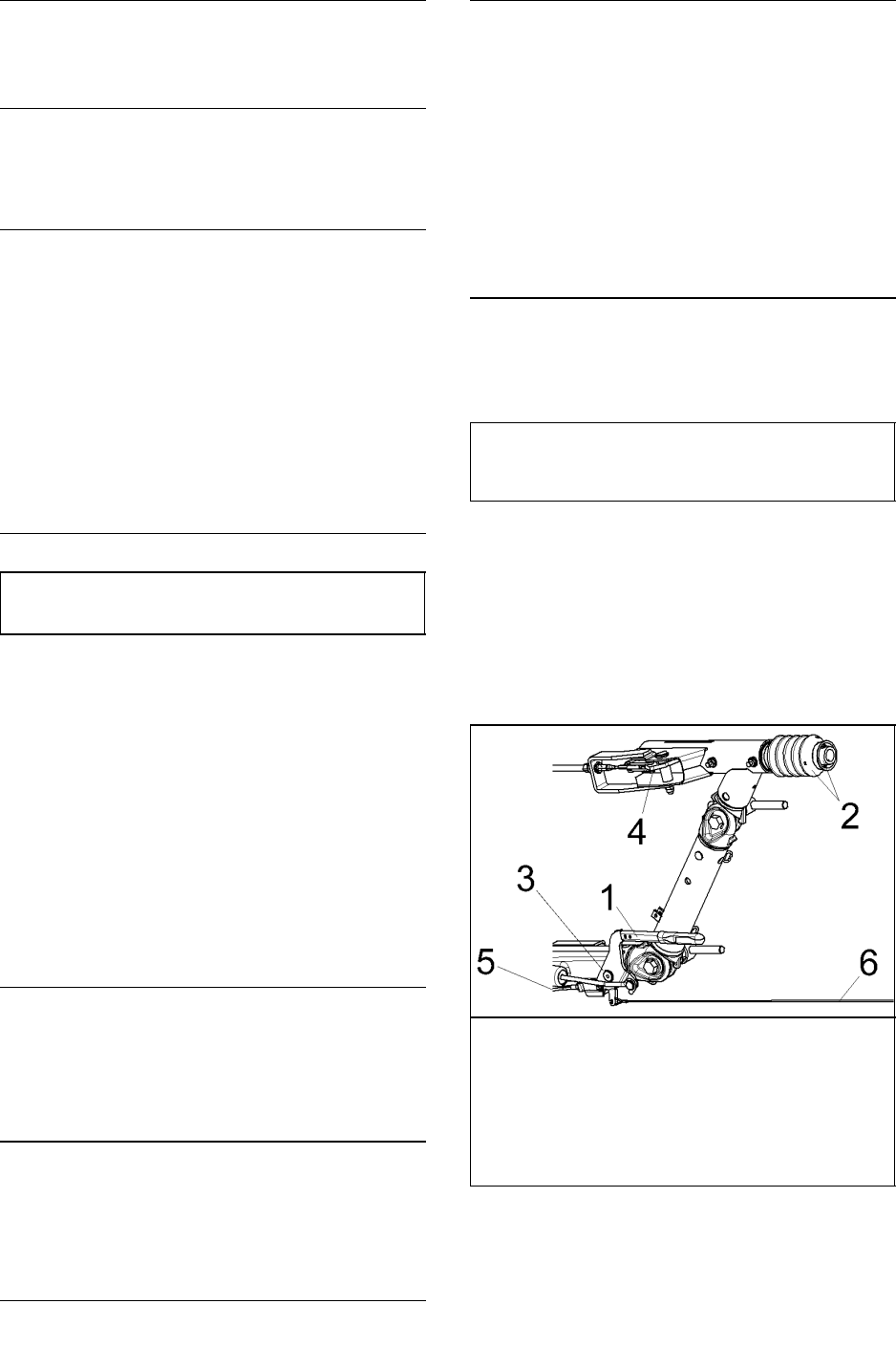
51 7/120 (P425AWIR), 9/110 (XP375AWIR), 10/105 (HP375AWIR), 14/85 (VHP300AWIR),
7/170 (P600WIR), 10/125 (HP450WIR), 14/115 (VHP400WIR)
FUEL FILTER WATER SEPARATOR
The fuel filter water separator contains a filter element which
should be replaced at regular intervals (see the
SERVICE/MAINTENANCE CHART).
CHARGE AIR COOLER PIPEWORK
Inspect all hoses and clips on the charge cooler pipe work.
Engine damage will occur if the charge cooling system leaks.
HOSES
All components of the engine cooling air intake system
should be checked periodically to keep the engine at peak
efficiency.
At the recommended intervals, (see the
SERVICE/MAINTENANCE CHART), inspect all of the intake
lines to the air filter, and all flexible hoses used for air lines, oil
lines and fuel lines.
Periodically inspect all pipework for cracks, leaks, etc. and
replace immediately if damaged.
ELECTRICAL SYSTEM
WARNING: Always disconnect the battery cables before
performing any maintenance or service.
Inspect the safety shutdown system switches and the
instrument panel relay contacts for evidence of arcing and
pitting. Clean where necessary.
Check the mechanical action of the components.
Check the security of electrical terminals on the switches
and relays i.e. nuts or screws loose, which may cause local hot
spot oxidation.
Inspect the components and wiring for signs of overheating
i.e. discolouration, charring of cables, deformation of parts,
acrid smells and blistered paint.
BATTERY
Keep the battery terminals and cable clamps clean and
lightly coated with petroleum jelly to prevent corrosion.
The retaining clamp should be kept tight enough to prevent
the battery from moving.
PRESSURE SYSTEM
At 500 hour intervals it is necessary to inspect the external
surfaces of the system (from the airend through to the discharge
valve(s)) including hoses, tubes, tube fittings and the separator
tank, for visible signs of impact damage, excessive corrosion,
abrasion, tightness and chafing. Any suspect parts should be
replaced before the machine is put back into service.
TYRES/TYRE/TIRE PRESSURE
See the GENERAL INFORMATION section of this manual.
RUNNING GEAR/WHEELS
Check the wheel nut torque 20 miles (30 kilometres) after
refitting the wheels. Refer to the TORQUE SETTING TABLE
later in this section.
Lifting jacks should only be used under the axle.
The bolts securing the running gear to the chassis should be
checked periodically for tightness (refer to the
SERVICE/MAINTENANCE CHART for frequency) and
re–tightened where necessary. Refer to the TORQUE
SETTING TABLE later in this section.
BRAKES
Check and adjust the brake linkage at 500 miles (850Km)
then every 3000 miles (5000Km) or 3 months (whichever is the
sooner) to compensate for any stretch of the adjustable cables.
Check and adjust the wheel brakes to compensate for wear.
CAUTION: Check the wheel nut torque 20 miles (30 kilometres)
after refitting the wheels (Refer to the TORQUE SETTING
TABLE later in this section).
Adjusting the overrun braking system
(KNOTT Running Gear)
1: Preparation
Jack up the machine
Disengage the handbrake lever [1].
Fully extend the draw bar [2] on the overrun braking system.
1 Handbrake lever
2 Draw bar and bellows
3 Handbrake lever pivot
4 Transmission lever
5 Brake cable
6 Breakaway Cable
Requirements:
During the adjustment procedure always start with the wheel
brakes.
Always rotate the wheel in the direction of forward movement.
Ensure that an M10 safety screw is fitted to the handbrake pivot.
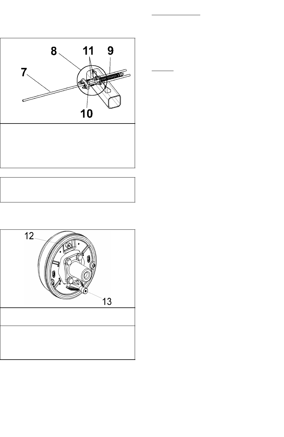
52
7/120 (P425AWIR), 9/110 (XP375AWIR), 10/105 (HP375AWIR), 14/85 (VHP300AWIR),
7/170 (P600WIR), 10/125 (HP450WIR), 14/115 (VHP400WIR)
The brake actuators must not be pre–tensioned – if necessary
loosen the brake linkage [7] on the brake equalisation assembly
[8].
Check that brake actuators and cables [11] operate smoothly.
7 Brake linkage
8 Equalisation assembly
9 Compression spring
10 Equaliser plate
11 Cable
CAUTION
The compression spring [9] must only be lightly pre–tensioned
and when operating must never touch the axle tube.
Never adjust the brakes at the brake linkage [7].
2. Brake Shoe Adjustment
12 Adjusting screw
13 Cable entry
Width across flats of adjusting screw [12]
Brake size Key width
160x35 / 200x50 SW 17
250x40 SW 19
300x60 SW 22
Tighten adjusting screw [12] clockwise until the wheel locks.
Loosen adjusting screw [12] anti–clockwise (approx. ½ turn)
until the wheel can be moved freely.
Slight dragging noises that do not impede the free movement of
the wheel are permissible.
This adjustment procedure must be carried out as described on
both wheel brakes.
When the brake has been adjusted accurately the actuating
distance is approximately 5–8mm on the cable [11]
3: Compensator assembly adjustment
Variable Height models
Fit an M10 safety screw to the handbrake pivot.
Disconnect the handbrake cable [5] at one end.
Pre–adjust brake linkage [7] lengthways (a little play is
permissible) and re–insert the cable [5], adjusting it to give a
small amount of play.
Remove the M10 safety screw from the handbrake pivot.
All Models
Engage the handbrake lever [1] and check that the position of
the equaliser plate [10] is at right angles to the pulling direction.
If necessary correct the position of the equaliser plate [10] on the
cables [11].
The compression spring [9] must only be slightly pre–tensioned
and when engaged must not touch the axle tube.
4: Brake linkage adjustment
Adjust the brake linkage [7] lengthways without pre–tension and
without play in the transmission lever [4].
Readjustment
Engage the handbrake lever [1] forcefully a number of times to
set the brake.
Check the alignment of the equalisation assembly [8], this
should be at right angles to the pulling direction
Check the play in the brake linkage [7]
If necessary adjust the brake linkage [7] again without play and
without pre–tensioning
There must still be a little play in cable [5] (Variable Height Only)
Check the position of the hand brake lever [1]. The start of
resistance should be approximately 10–15mm above the
horizontal position.
Check that the wheels move freely when the handbrake is
disengaged.
Final test
Check the fastenings on the transmission system (cables,
brake equalisation system and linkage).
Check the handbrake cable [5] for a small amount of play and
adjust if necessary (Variable height only)
Check the compression spring [9] for pre–tensioning.
Test run
If necessary carry out 2–3 test brake actions.
Test brake action
Check the play in brake linkage [7] and if necessary adjust the
length of brake linkage [7] until there is no play.
Apply the handbrake while rolling the machine forward, travel of
the handbrake lever up to 2/3 of maximum is allowed.
Re–adjusting the overrun braking system
(KNOTT Running Gear)
Re–adjustment of the wheel brakes will compensate for brake
lining wear. Follow the procedure described in 2: Brake Shoe
Adjustment.

53 7/120 (P425AWIR), 9/110 (XP375AWIR), 10/105 (HP375AWIR), 14/85 (VHP300AWIR),
7/170 (P600WIR), 10/125 (HP450WIR), 14/115 (VHP400WIR)
Check the play in the brake linkage [7] and re–adjust if
necessary.
Important
Check the brake actuators and cables [11]. The brake actuators
must not be pre–tensioned.
Excessive operation of the handbrake lever, which may have
been caused by worn brake linings, must not be corrected by
re–adjusting (shortening) the brake linkage [7]
Re–adjustment
The handbrake lever [1] should be engaged forcefully several
times to set the braking system.
Check the setting of the brake equalisation assembly [8], which
should be at right angles to the pulling direction.
Check the play in the brake linkage [7] again, ensuring that there
is no play in the brake linkage and that it is adjusted without
pre–tension
Check the position of the hand brake lever [1], cable [5] (with
little play) and the compression spring [9] (only slight
pre–tension). The start of resistance of the handbrake lever
should be approximately 10–15mm above the horizontal
position.
Final test
Check the fastenings on the transmission system (cables,
brake equalisation system and linkage)
Apply the handbrake while rolling the machine forward, travel of
the handbrake lever up to 2/3 of maximum is allowed.
Check the handbrake cable [5] for a small amount of play and
adjust if necessary (Variable height only)
Check the compression spring [9] for slight pre–tensioning.
LUBRICATION
The engine is initially supplied with engine oil sufficient for a
nominal period of operation (for more information, consult the
Engine section of this manual).
CAUTION: Always check the oil levels before a new machine
is put into service.
If, for any reason, the unit has been drained, it must be
re–filled with new oil before it is put into operation.
ENGINE LUBRICATING OIL
The engine oil should be changed at the engine
manufacturer’s recommended intervals. Refer to the Engine
section of this manual.
ENGINE LUBRICATING OIL SPECIFICATION
Refer to the Engine section of this manual.
ENGINE OIL FILTER ELEMENT
The engine oil filter element should be changed at the engine
manufacturer’s recommended intervals. Refer to the Engine
section of this manual.
COMPRESSOR LUBRICATING OIL
Refer to the SERVICE/MAINTENANCE CHART in this
section for service intervals.
NOTE: If the machine has been operating under adverse
conditions, or has suffered long shutdown periods, then more
frequent service intervals will be required.
WARNING: DO NOT, under any circumstances, remove any
drain plugs or the oil filler plug from the compressor
lubricating and cooling system without first making sure
that the machine is stopped and the system has been
completely relieved of all air pressure (refer to STOPPING
THE UNIT in the OPERATING INSTRUCTIONS section of this
manual).
Completely drain the receiver/separator system including
the piping and oil cooler by removing the drain plug(s) and
collecting the used oil in a suitable container.
Replace the drain plug(s) ensuring that each one is secure.
NOTE: If the oil is drained immediately after the machine has
been running, then most of the sediment will be in suspension
and will therefore drain more readily.
CAUTION: Some oil mixtures are incompatible and result in the
formation of varnishes, shellacs or lacquers which may be
insoluble.
NOTE: Always specify INGERSOLL–RAND Pro–TecTM oil for
use at all ambient temperatures above –23C.
COMPRESSOR OIL FILTER ELEMENT
Refer to the SERVICE / MAINTENANCE CHART in this
section for service intervals.
RUNNING GEAR WHEEL BEARINGS
Wheel bearings should be packed with grease every 6
months. The type of grease used should conform to
specification MIL–G–10924.
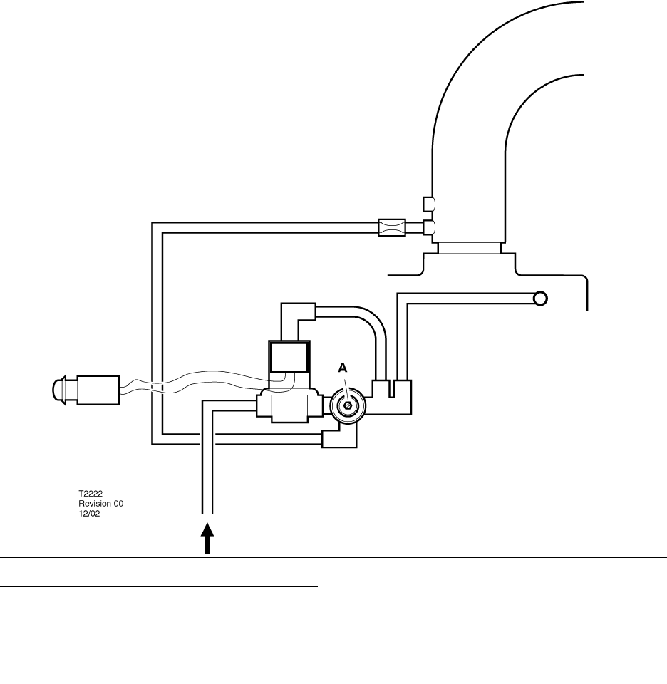
54
7/120 (P425AWIR), 9/110 (XP375AWIR), 10/105 (HP375AWIR), 14/85 (VHP300AWIR),
7/170 (P600WIR), 10/125 (HP450WIR), 14/115 (VHP400WIR)
SPEED AND PRESSURE REGULATION ADJUSTMENT
Normally, regulation requires no adjusting, but if correct
adjustment is lost, proceed as follows:
Refer to the diagram above.
A: Adjusting screw
Start the machine (Refer to STARTING INSTRUCTIONS in
the OPERATING INSTRUCTIONS section of this manual).
Adjust the service valve on the outside of the machine to
maintain rated pressure at full speed. If full speed is not
maintained at rated pressure, then turn the adjusting screw
clockwise to increase the pressure. Optimum adjustment is
achieved when full speed is achieved at rated pressure.
Close the service valve. The engine will slow to idle speed.
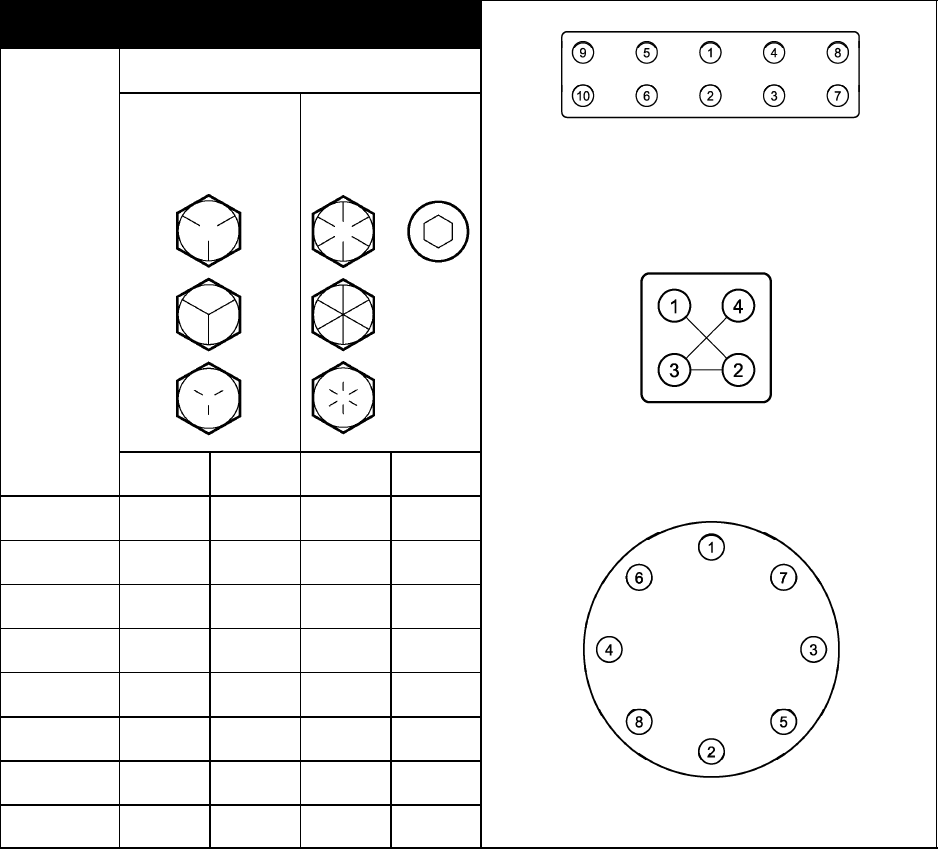
55 7/120 (P425AWIR), 9/110 (XP375AWIR), 10/105 (HP375AWIR), 14/85 (VHP300AWIR),
7/170 (P600WIR), 10/125 (HP450WIR), 14/115 (VHP400WIR)
TABLE 1 INCH FASTENERS
NOMINAL DESIGN TORQUE
8AE J249
GRADE 5
(HEAD MARKING)
8AE J249
GRADE 8
(HEAD MARKING)
TYPICAL RECTANGULAR TORQUE
PATTERN
CAPSCREW
OR NUT
THREAD
SIZE AND
PITCH
TYPICAL SQUARE TORQUE
PATTERN
(Nm.) (FT–LBF) (Nm.) (FT–LBF)
1/4 – 20 11 8 16 12
5/16 – 18 24 17 33 25
3/8 – 16 42 31 59 44
7/16 – 14 67 49 95 70
1/2 – 13 102 75 144 106
9/16 – 12 148 109 208 154
5/8 – 11 203 150 287 212 TYPICAL CIRCULAR TORQUE
3/4 – 10 361 266 509 376
TYPICAL CIRCULAR TORQUE
PATTERN
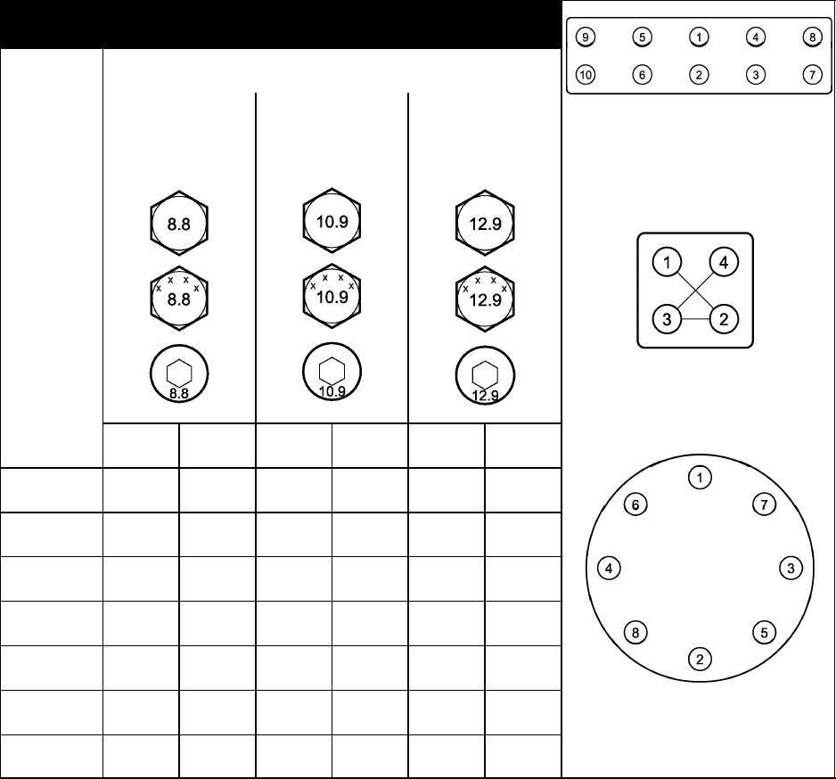
56
7/120 (P425AWIR), 9/110 (XP375AWIR), 10/105 (HP375AWIR), 14/85 (VHP300AWIR),
7/170 (P600WIR), 10/125 (HP450WIR), 14/115 (VHP400WIR)
TABLE 2 METRIC FASTENERS
NOMINAL DESIGN TORQUE
PROPERTY
GRADE 8.8
(HEAD MARKING)
PROPERTY
GRADE 10.9
(HEAD MARKING)
PROPERTY
GRADE 12.9
(HEAD MARKING)
TYPICAL RECTANGULAR TORQUE
PATTERN
CAPSCREW
OR NUT
THREAD
SIZE AND
PITCH
TYPICAL SQUARE TORQUE
PATTERN
(Nm.) (FT–LBF) (Nm.) (FT–LBF) (Nm.) (FT–LBF)
M6 X 1.0 11 815 11 18 13
M8 X 1.25 26 19 36 27 43 31
M10 X 1.5 52 38 72 53 84 62
M12 X 1.75 91 67 126 93 147 109
M14 X 2 145 107 200 148 234 173
M16 X 2 226 166 313 231 365 270 TYPICAL CIRCULAR TORQUE
PATTERN
M20 X 2.5 441 325 610 450 713 526
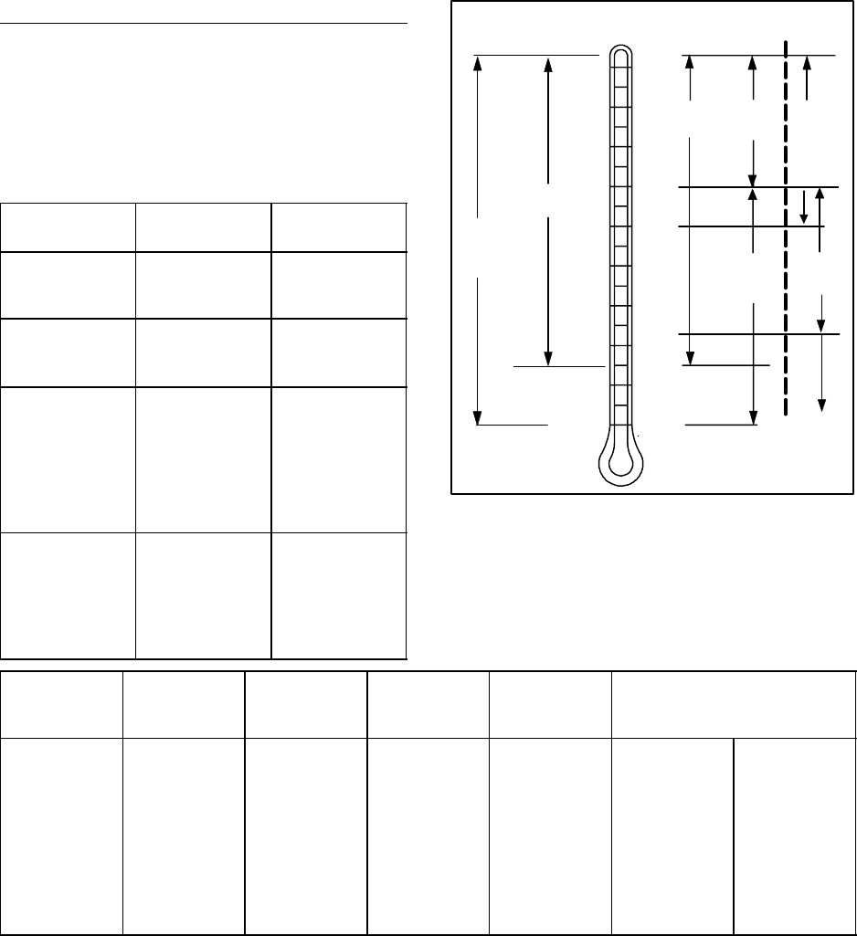
57 7/120 (P425AWIR), 9/110 (XP375AWIR), 10/105 (HP375AWIR), 14/85 (VHP300AWIR),
7/170 (P600WIR), 10/125 (HP450WIR), 14/115 (VHP400WIR)
COMPRESSOR LUBRICATION
Portable Compressor Fluid Chart
Refer to these charts for correct compressor fluid required.
Note that the selection of fluid is dependent on the design
operating pressure of the machine and the ambient
temperature expected to be encountered before the next oil
change.
Design Operating
Pressure
Ambient
Temperature
Specification
100 psi to 300 psi –10F to 125F
(–23C to 52C)
IR Pro–Tec
Mil –PRF 2104G
SAE 10W
100 psi to 300 psi –40F to 125F
(–40C to 52C)
IR Performance
500
Mil–L–46167
350 psi –10F to 125F
(–23C to 52C)
65F to 125F
(18C to 52C)
–40F to 65F
(–40C to 18C)
IR XHP 505
IR XHP1001
IR Performance
500
Mil–L–46167
500 psi 50F to 125F
(10C to 52C)
10F to 65F
(–12C to 18C)
below 10F
(–12C)
IR XHP1001
IR XHP 505
Consult Factory
IR
XHP505 IR
XHP1001
IR
PERFORMANCE
500
IR
PRO–TEC
100 – 300 PSI
RATED OPERATING PRESSURE
350 PSI 500 PSI
IR
XHP 1001
IR
500
PERFORMANCE IR
XHP505
10F
125F
50C
40C
30C
20C
10C
0C
–10C
–20C
–30C
–40C
104F
86F
65F
50F
32F
14F
–10F
–22F
–40Fconsult
factory
Recommended Ingersoll–Rand Fluids – Use of these fluids
with original IR filters can extend airend warranty. Refer to
operator’s manual warranty section for details or contact your
IR representative.
Compressor
Recommended
Fluid
1 Gal. 5 Gal. 55 Gal. 275 Gal. Tote Europe
20 Litre 208 Litre
Pro–Te c 36899698 36899706 36899714 36899722 89292973 89292981
XHP 505 NA 54418835 54418843 54418827 ___ –––
Performance
500 35382928 35382936 35382944 NA ___ –––
XHP1001 NA 35612738 35300516 NA ___ ___
Engine Oil 54480918 36875938 36866903 NA 89311716 89311724
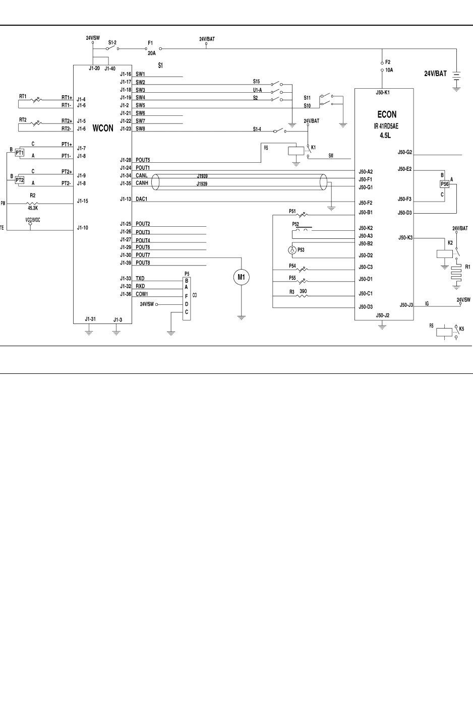
58
7/120 (P425AWIR), 9/110 (XP375AWIR), 10/105 (HP375AWIR), 14/85 (VHP300AWIR),
7/170 (P600WIR), 10/125 (HP450WIR), 14/115 (VHP400WIR)
MACHINE SYSTEMS
KEY
BAT Battery
CO RS232C comms
ECON Engine controller
IG Isochronous governor
J50–G2 Wait to start lamp
J50–K3 Inlet heater
P51 Coolant temp
P52 Inject
P53 Crank sensor
P54 Fuel temp
P55 Manifold air temp
P56 Oil pressure
POUT1 Engine key switch
POUT2 Solenoid, start/run
POUT3 Comp fault lamp
POUT4 Engine fault lamp
POUT5 Start relay
POUT6 Spare
POUT7 Hour meter
POUT8 Spare
PT1 Pressure transducer, separator tank 0–500 PSIG
PT2 Pressure transducer, regulation system 0–100 PSIG
PM Plug, machine ID
R3 Idle sel
RS Relay–spst
RT1 Thermistor, seperator tank temperature –30 – 255F
RT2 Thermistor, airend discharge temperature –30 –
255F
SI Switch inputs
SM Starter motor
SW1 Spare
SW2 Display scroll
SW3 Low fuel shutdown
SW4 Switch, service air
SW5 Air filter rest (option)
SW6 Spare
SW7 Spare
SW8 Switch, start
TE Transducer exitation
WCON Wedge controller
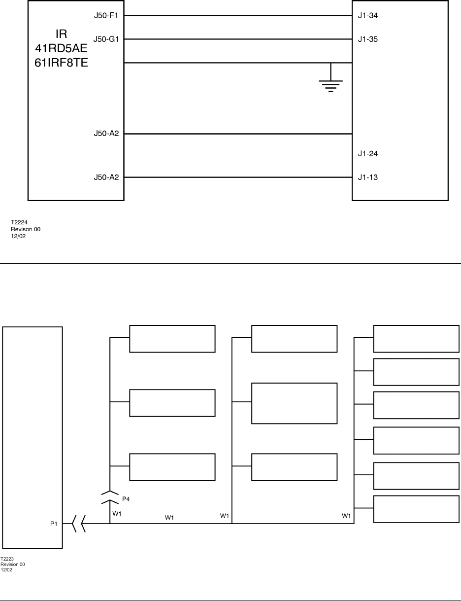
59 7/120 (P425AWIR), 9/110 (XP375AWIR), 10/105 (HP375AWIR), 14/85 (VHP300AWIR),
7/170 (P600WIR), 10/125 (HP450WIR), 14/115 (VHP400WIR)
WEDGE
CONTROLLER
CAN HI
CAN LO
CAN SHLD
KEY SWITCH
ANALOG THROTTLE RANGE=
1.10VDC (1400RPM) TO 3.7VDC (2400RPM)
ANALOG THROTTLE
ENGINE
CONTROLLER
FIGURE 2–1
WEDGE TO ENGINE INTERFACE – IR ENGINE
CONTROLL PANEL HARNESS
SOLENOID VALVES
ENGINE ECM
DIAGNOSTIC
INTERFACE
24VDC HEATERS
GUAGES
HOURMETER
CONTROL PANEL
SWITCHES
WEDGE
CONTROLLER
SPEED SENSOR
FUEL LEVEL SWITCH
PRESSURE
TRANSDUCER
TEMPERATURE
SENSOR
BATTERY STARTING
AND CHARGING
SYSTEM
ESTOP SWITCHES
HARNESS SYSTEM SCHEMATIC
FIGURE 2–2
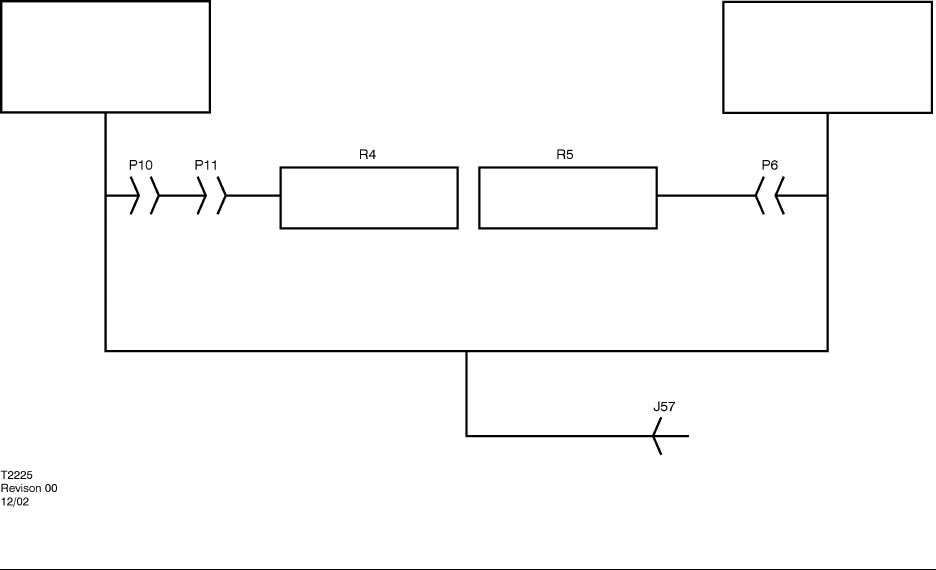
60
7/120 (P425AWIR), 9/110 (XP375AWIR), 10/105 (HP375AWIR), 14/85 (VHP300AWIR),
7/170 (P600WIR), 10/125 (HP450WIR), 14/115 (VHP400WIR)
ENGINE CM
TERMINATOR
J1939 CAN COMMUNICATIONS SCHEMATIC
FIGURE 2–3
ENGINE DIAGNOSTICS
JACK
WEDGE
CONTROLLER
TERMINATOR

61 7/120 (P425AWIR), 9/110 (XP375AWIR), 10/105 (HP375AWIR), 14/85 (VHP300AWIR),
7/170 (P600WIR), 10/125 (HP450WIR), 14/115 (VHP400WIR)
SERVICE TOOLS
Electronic Systems
The following special tools are recommended to perform service procedures in this manual.
The tools can be purchased from Ingersoll–Rand or equivalent substitutes can be used.
Tool Tool Description
Fluke 87 Digital Multimeter
Used to Measure electrical circuits:
volts, ohms amps
54729660 Weather–Pack Terminal Removal Tool
Used to repair Packard Electric Weather–Pack Connectors
54729678 Deutsch Terminal Removal Tool (Blue)
Used to repair Deutsch connectors
54729686 Deutsch Terminal Removal Tool (Red)
Used to repair Deutsch connectors
54729694 Deutsch Terminal Removal Tool (Yellow)
Used to repair Deutsch connectors
HDT–48–00 Deutsch Terminal Crimp Tool
Used to crimp Deutsch connector terminals
DD Deutsch Terminal Crimping Tool
Used to crimp Deutsch connector terminals
54729710 Electrical Contact Cleaner
Used to clean electrical contacts and connectors
54729728 PDA Service Tool
Palm Pilot based service tool used to connect to Intellisys (SGP) Controller
to load software and extract service information
22073886 Packard Crimp Tool
Used to crimp Packard connector terminals
22073878 Thermistor Simulator Plug
Used to test thermister circuits
54699616 Deutsch Terminal Removal Tool
Used to repair Deutsch connectors
54699657 Deutsch Terminal Removal Tool
Used to repair Deutsch connectors
54749643 Packard Metri–Pack Terminal Removal Tool
Used to repair Metri–Pack connectors
54749635 Connector Repair Kit
Used to make connector repairs
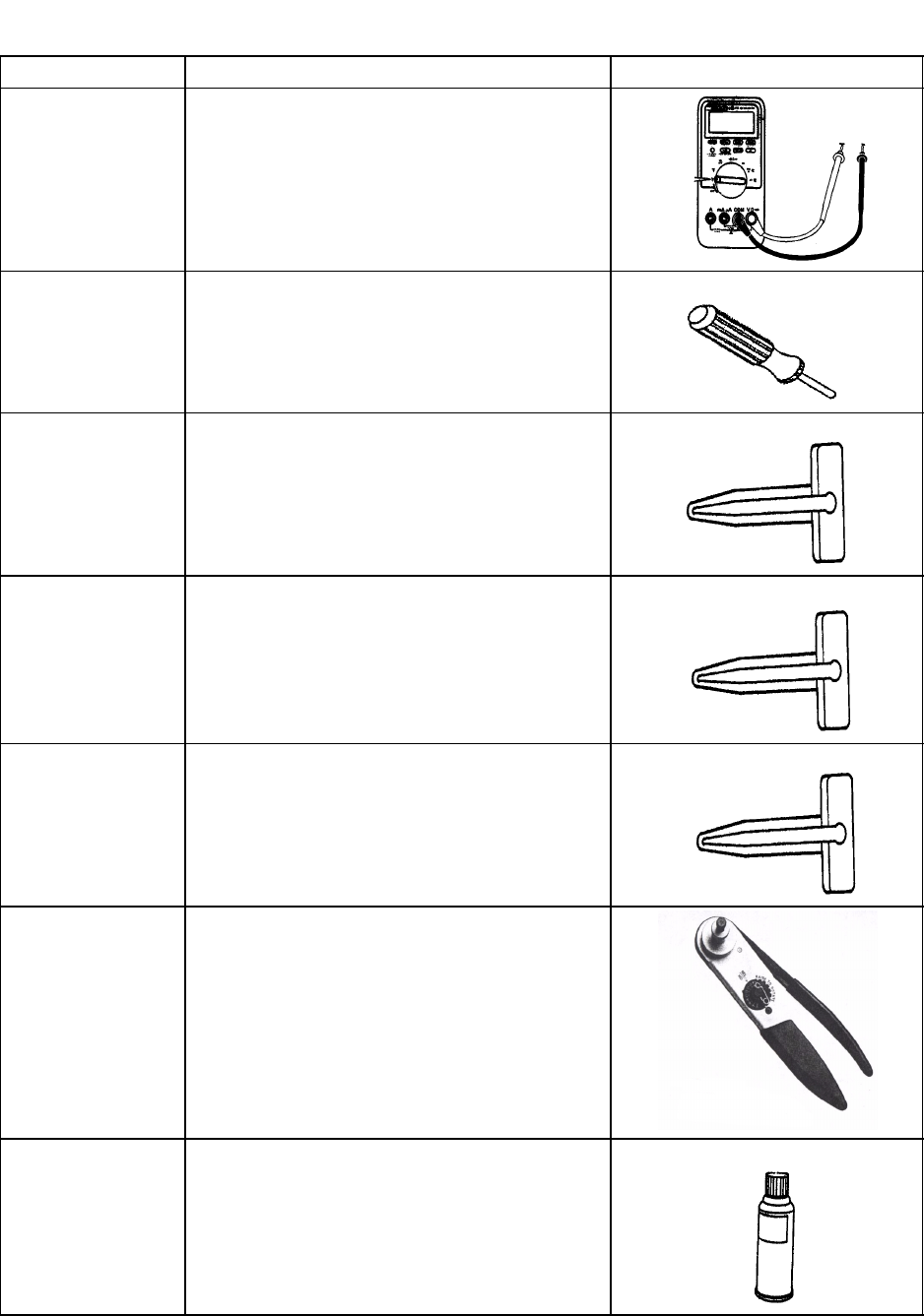
62
7/120 (P425AWIR), 9/110 (XP375AWIR), 10/105 (HP375AWIR), 14/85 (VHP300AWIR),
7/170 (P600WIR), 10/125 (HP450WIR), 14/115 (VHP400WIR)
SERVICE TOOLS
Tool No. Tool Description Tool Illustration
Fluke 87 Digital Multimeter
Available from electrical and electronic
parts distributors.
54729660 Weather–Pack Terminal Removal Tool
54699632 Deutsch Terminal Removal Tool (Blue)
54699640 Deutsch Terminal Removal Tool (Red)
54699624 Deutsch Terminal Removal Tool (Yellow)
DT–RT1 Crimp Tool for Deutsch Pins Crimp
Available from:
Ladd Industries (800–223–1236)
54729710 Electrical Contact Cleaner
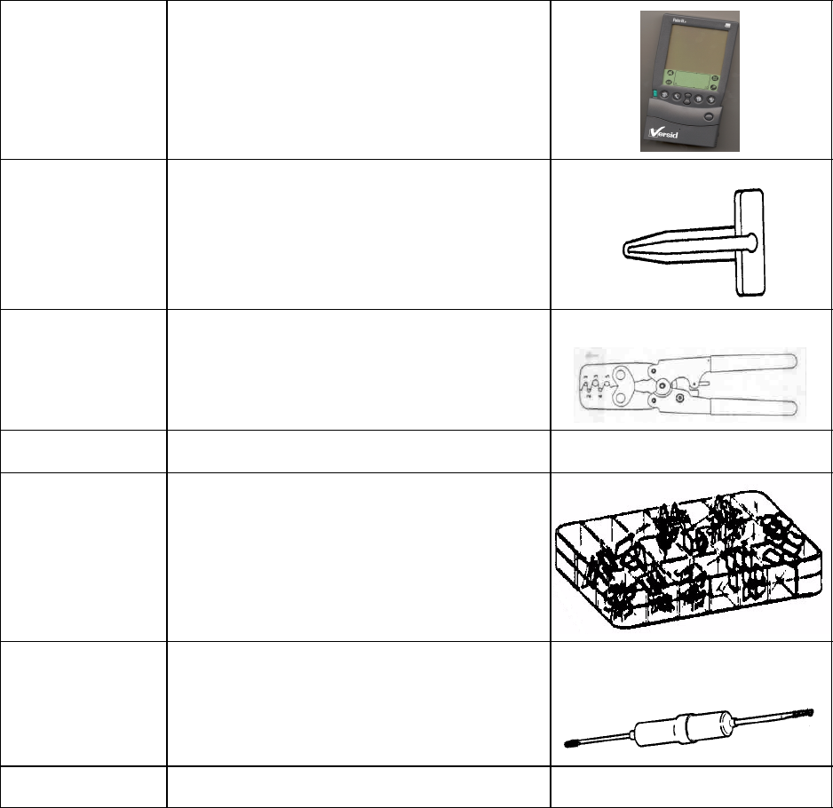
63 7/120 (P425AWIR), 9/110 (XP375AWIR), 10/105 (HP375AWIR), 14/85 (VHP300AWIR),
7/170 (P600WIR), 10/125 (HP450WIR), 14/115 (VHP400WIR)
54729728 PDA Service Tool
54699616 Deutsch Terminal Removal Tool
22073886 Packard Crimp Tool
22073878 Thermistor Simulator
54749635 Connector Repair Kit
54699657 Deutsch Terminal Removal Tool
54749643 Packard Metri–Pack Removal Tool

64
7/120 (P425AWIR), 9/110 (XP375AWIR), 10/105 (HP375AWIR), 14/85 (VHP300AWIR),
7/170 (P600WIR), 10/125 (HP450WIR), 14/115 (VHP400WIR)
ELECTRICAL PARTS
PARTS
NUMBERS DESCRIPTION QTY PER
MACHINE PARTS
NUMBERS DESCRIPTION QTY PER
MACHINE
36920825 0–100 psi PRESSURE
TRANSDUCER 1
54765946 0–500 psi PRESSURE
TRANSDUCER 1
36898922 THERMISTOR PROBE 2
36840841 SOLENOID VALVE 1*
36853521 STARTER AND INLET
HEATER RELAY 2
35610856 NEGATIVE BATTERY
CABLE 1
35583582 POSITIVE BATTERY
CABLE 1
35578194 ENGINE GROUND
STRAP 1
54731427 FUEL LEVEL SENDER 1
22173579 WEDGE CONTROLLER 1
22199061 W1 CHASSIS HARNESS 1
22179659 W1 CHASSIS HARNESS
DIAGRAM N/A
36792083 FUSE 20 AMP BLADE 1
22071591 FUSE 10 AMP BLADE 1
54475777 DIAGNOSTIC SWITCH 1
** MACHINE ID PLUG 1
* Quantity two (2) per machine on P600WIR (7/170) model only.
** Part number 22201354 on models 7/120 (P425AWIR), 9/110 (XP375AWIR), 10/105 (HP375AWIR), and 14/85 (VHP300AWIR).
Part number 22201362 on models 7/170 (P600WIR), 10/125 (HP450WIR), and 14/115 (VHP400WIR).

FAULT FINDING
65 7/120 (P425AWIR), 9/110 (XP375AWIR), 10/105 (HP375AWIR), 14/85 (VHP300AWIR),
7/170 (P600WIR), 10/125 (HP450WIR), 14/115 (VHP400WIR)
FAULT CAUSE REMEDY
No reaction
from
instrument
Batteries not
connected. Connect batteries.
panel when
key turned
to (I)
position.
Fuse at starter motor
‘blown’.Replace fuse.
Engine fails
to start. Low battery charge. Check the fan belt
tension, battery and
cable connections.
Bad earth
connection. Check the earth
cables, clean as
required.
Loose connection. Locate and make the
connection good.
Fuel starvation. Check the fuel level
and fuel system
components.
Replace the fuel filter
if necessary.
Relay failed. Replace the relay.
Faulty stop solenoid Check the stop
solenoid
Engine
stops while
in service or
is reluctant
to start.
Low fuel level. Fill fuel tank and bleed
air from fuel system if
necessary. (Refer to
MAINTENANCE
SECTION).
Safety shut-down
system in operation. Check the safety
shut-down switches.
Engine
starts but Electrical fault Test the electrical
circuits.
stalls when
the switch
returns to
Low engine oil
pressure. Check the oil level
and the oil filter(s).
position I.Faulty relay Check the relays.
Faulty key–switch Check the
key–switch.
Engine
starts but
will not run
Electrical fault. Test the electrical
circuits.
will not run
or engine
shuts down
prematurely.
Low engine oil
pressure. Check the oil level
and oil filter(s).
Engine
starts but Safety shut-down
system in operation. Check the safety
shut-down switches.
will not run
or engine
shuts down
prematurely.
Fuel starvation. Check the fuel level
and fuel system
components.
Replace the fuel filter
if necessary.
Switch failure. Test the switches.
High compressor oil
temperature. Check the
compressor oil level
and oil cooler. Check
the fan drive.
Water present in fuel
system. Check the water
separator and clean if
required.
Faulty relay. Check the relays and
replace if necessary.
Engine
Overheats. Low water level Check the level and
replenish if
necessary.
Blocked radiator. Stop the machine and
clean the cooling fins
with compressed air
or steam. Use
reduced pressure for
cleaning the fins.
Reduced cooling air
from fan. Check the fan and the
drive belts. Check for
any obstruction inside
the cowl.
Faulty thermostat Check the thermostat
and replace if
necessary.
Engine
speed too
high.
Incorrect throttle arm
setting. Check the engine
speed setting.
Engine
speed too Incorrect throttle arm
setting. Check the throttle
setting.
low. Blocked fuel filter. Check and replace if
necessary.
Blocked air filter. Check and replace
the element if
necessary.
Incorrectly set
regulation system. Reset the regulation
system. Refer to
SPEED AND
PRESSURE
REGULATION
ADJUSTMENT in the
MAINTENANCE
section of this
manual.
Premature
unloading. Check the regulation
system.
Excessive
vibration. Engine speed too
low. See ”Engine speed
too low”
Leaking oil
seal. Improperly fitted oil
seal. Replace the oil seal.
Refer also to the Engine Manufacturer’s Manual.
Air
discharge Engine speed too
low. See “Engine speed
too low”
capacity too
low. Blocked air cleaner. Check the restriction
indicators and replace
the element(s) if
necessary.
High pressure air
escaping. Check for leaks.
Incorrectly set
regulation system. Reset the regulation
system. Refer to
SPEED AND
PRESSURE
REGULATION
ADJUSTMENT in the
MAINTENANCE
section of this
manual.

FAULT FINDING
66
7/120 (P425AWIR), 9/110 (XP375AWIR), 10/105 (HP375AWIR), 14/85 (VHP300AWIR),
7/170 (P600WIR), 10/125 (HP450WIR), 14/115 (VHP400WIR)
Compressor
overheats. Low oil level. Top up the oil level and
check for leaks.
Dirty or blocked oil
cooler. Clean the oil cooler
fins.
Incorrect grade of
oil. Use Ingersoll–Rand
recommended oil.
Defective by-pass
valve. Check the operation
of the element and
replace if necessary.
Recirculation of
cooling air. Move the machine to
avoid recirculation.
Reduced cooling air
from fan. Check the fan and the
drive belts. Check for
any obstruction inside
the fan cowl.
Excessive oil
present in
the
discharge
Blocked scavenge
line. Check the scavenge
line, drop tube and
orifice. Clean and
replace.
air. Perforated separator
element. Replace the
separator element.
Pressure in the
system is too low. Check the minimum
pressure valve.
Safety valve
operates. Operating pressure
too high. Refer to SPEED AND
PRESSURE RE-
GULATION AD-
JUSTMENT in the
MAINTENANCE sec-
tion of this manual.
Incorrect setting of
the regulator. Adjust the regulator.
Faulty regulator. Replace the regulator.
Inlet valve set
incorrectly. Refer to SPEED AND
PRESSURE
REGULATION
ADJUSTMENT in the
MAINTENANCE
section of this
manual.
Loose pipe/hose
connections. Check all pipe/hose
connections.
Faulty safety valve. Check the relieving
pressure. Replace
the safety valve if
faulty. DO NOT
ATTEMPT A
REPAIR.
Oil is forced
back into the
air filter.
Incorrect stopping
procedure used Always employ the
correct stopping
procedure. Close the
discharge valve and
allow the machine to
run on idle before
stopping.
Faulty inlet valve. Check for free
operation of the inlet
valve(s).
Machine
goes to full
pressure
when
started.
Faulty load valve. Replace the valve.
Machine fails Faulty load valve. Replace the valve.
to load when
the load Faulty switch. Test switch
the load
switch is
pressed. Loose pipe/hose
connections. Check all pipe/hose
connections.

OPTIONS
7/120 (P425AWIR), 9/110 (XP375AWIR), 10/105 (HP375AWIR), 14/85 (VHP300AWIR),
7/170 (P600WIR), 10/125 (HP450WIR), 14/115 (VHP400WIR)
67
OPTIONS – Lubricator
(For units manufactured in North America)
SAFETY
WARNING: Ensure that the lubricator filler cap is
re–tightened correctly after replenishing with oil.
WARNING: Do not replenish the lubricator oil, or service
the lubricator without first making sure that the machine is
stopped and the system has been completely relieved of all
air pressure (Refer to STOPPING THE UNIT in the
OPERATING INSTRUCTIONS section of this manual).
CAUTION: If the nylon tubes to the lubricator are disconnected
then ensure that each tube is re–connected in its original
location.
GENERAL INFORMATION
Oil capacity:
1 QT Option –0.95 Litre (1qt)
2 QT Option –1.9 Litre (2qts)
Oil specification:
Refer to the Tool Manufacturer’s Manual.
OPERATING INSTRUCTIONS
COMMISSIONING
Check the lubricator oil level and fill as necessary.
PRIOR TO STARTING
Check the lubricator oil level and replenish as necessary.
MAINTENANCE
Check the lubricator oil level and replenish as necessary.
FAULT FINDING
FAULT CAUSE REMEDY
No oil flow. Incorrect connection. Reverse the nylon
tube connections to
the lubricator.
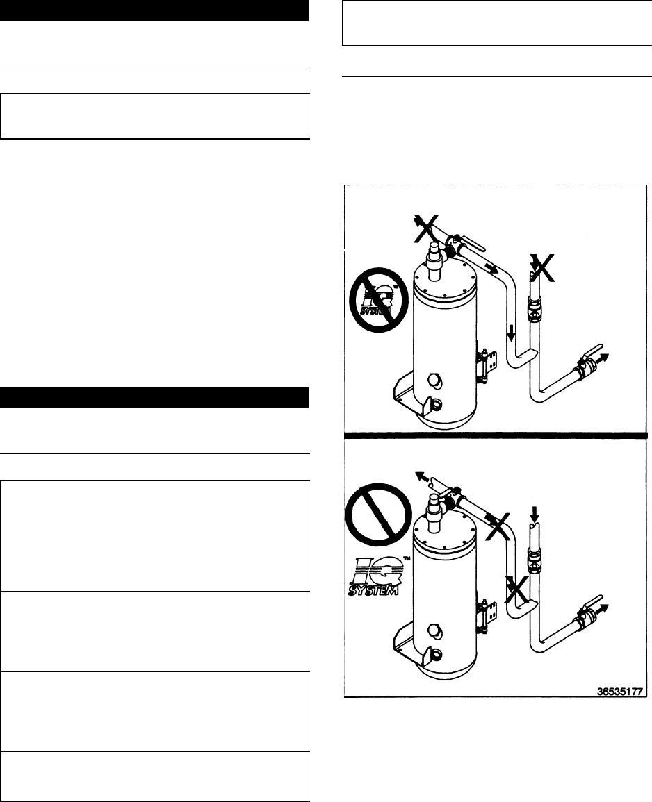
OPTIONS
7/120 (P425AWIR), 9/110 (XP375AWIR), 10/105 (HP375AWIR), 14/85 (VHP300AWIR),
7/170 (P600WIR), 10/125 (HP450WIR), 14/115 (VHP400WIR) 68
OPTIONS – Dual pressure
SAFETY
WARNING: Any pneumatic equipment that is, or may be
connected to the machine must be suitable for use with at
least the higher, rated pressure.
OPERATING INSTRUCTIONS
COMMISIONING
Check that switch and solenoid are functioning correctly.
Switch handle up: Lower pressure selected
Switch handle right: Higher pressure selected
STARTING AND USE
Select higher pressure setting with valve handle (handle to
right) and start machine normally.
If lower pressure is required then turn handle to up position.
Toggle between high and low pressure as required.
OPTIONS – IQ SYSTEM
SAFETY
CAUTION: The compressor regulation system is adjusted to
maintain regulated pressure at the separator tank. DO NOT
adjust regulation to provide full regulation pressure at the
service valve when the IQ System is enabled. This will result
inC operation at excessive horsepower levels, causing
overheating, reduced engine life, and reduced airend life.
CAUTION: Excessively restricted filter elements may cause an
increase in the amount of aerosol water and oil carryover, which
could result in damage to downstream equipment. Normal
service intervals should not be exceeded.
CAUTION: Blockage of the condensate will result in flooding of
the vessels. If flooding occurs, excessive condensate may
enter the air stream and could result in damage to downstream
equipment.
CAUTION: Do not remove u–bolts from both filters at the same
time. Removing both u–bolts will place excessive stress on the
aftercooler.
NOTICE:
Do not operate at temperatures less that 2C (35F) unless
equipped with low ambient IQ option.
OPERATING INSTRUCTIONS
Starting and use:
Select desired air type using diverter valve and start machine
normally.
Using diverter valve, toggle between standard air and IQ air as
required.
TO AFTERCOOLER
Standard
Operation
FROM FILTERS
SERVICE AIR
TO AFTERCOOLER
Standard
Operation
FROM FILTERS
SERVICE AIR

OPTIONS
7/120 (P425AWIR), 9/110 (XP375AWIR), 10/105 (HP375AWIR), 14/85 (VHP300AWIR),
7/170 (P600WIR), 10/125 (HP450WIR), 14/115 (VHP400WIR)
69
MAINTENANCE
Daily maintenance:
Verify, during full–load (maximum compressed air delivery) that
the IQ system filter restriction indicators do not show excessive
restriction.
Restriction indicators for primary and secondary filters are
located on the filter heads. If so equipped, an automatic
restriction indicator is located behind the filter mounting bracket
and will shut down the compressor if restriction exceeds
recommended values.
Weekly Maintenance:
Verify that the piping from the water separator and filters to
the exhaust system is not clogged.
Yearly Maintenance:
The normal maintenance interval on the primary and secondary
IQ System filters is one year, or earlier if pressure drop becomes
excessive.
Restriction indicators for the filters are mounted on the filter
heads. If so equipped, an automatic restriction indicator located
behind the filters will shut down the compressor if restriction
exceeds recommended values.
Filter replacement.
Remove all wires and hoses connected to drains on bottom
of each filter housing. Inspect fittings and hoses for any
blockage. Clean if necessary.
Using a chain wrench or similar tool, loosen the housing. The
housing should be removed by hand after loosening, taking care
to prevent the housing from falling to the floor panel.
Lower the housing to floor panel. Remove and replace the
filter element, being careful not to damage outer wrap.
Put a small amount of petroleum jelly or other non–synthetic
grease on the element o–ring to aid installation into the filter
head.
Replace housing making sure not to overtighten.
Repeat the above procedure on the remaining filter element.
Rec onnect all wires and hoses to drains on bottom of each
filter housing.

70
7/120 (P425AWIR), 9/110 (XP375AWIR), 10/105 (HP375AWIR), 14/85 (VHP300AWIR),
7/170 (P600WIR), 10/125 (HP450WIR), 14/115 (VHP400WIR)
PARTS ORDERING
GENERAL
This publication, which contains an illustrated
parts breakdown, has been prepared as an aid in
locating those parts which may be required in the
maintenance of the unit. All of the compressor
parts, listed in the parts breakdown, are
manufactured with the same precision as the
original equipment. For the greatest protection
always insist on genuine Ingersoll–Rand
Company parts for your compressor.
NOTICE
Ingersoll–Rand Company can bear no
responsibility for injury or damages resulting
directly from the use of non–approved repair
parts.
Ingersoll–Rand Company service facilities and
parts are available worldwide. There are
Ingersoll– Rand Company Construction
Equipment Group Sales Offices and authorized
distributors located in the principal cities of the
United States. In Canada our customers are
serviced by the Canadian Ingersoll–Rand
Company, Limited. There are also
Ingersoll–Rand International autonomous
companies and authorized distributors located in
the principal cities throughout the free world.
Special order parts may not be included in this
manual. Contact the Mocksville Parts Department
with the unit serial number for assistance with
these special parts.
DESCRIPTION
The illustrated parts breakdown illustrates and
lists the various assemblies, subassemblies and
detailed parts which make up this particular
machine. This covers the standard models and
the more popular options that are available.
A series of illustrations show each part distinctly
and in location relative to the other parts in the
assembly. The part number, the description of the
part and the quantity of parts required are shown
on each illustration or on adjacent page. The
quantities specified are the number of parts used
per one assembly and are not necessarily the total
number of parts used in the machine. Where no
quantity is specified the quantity is assumed to be
one.
Each description of a part is based upon the “noun
first” method, i.e., the identifying noun or item
name is always the first part of the description.
The noun name is generally followed by a single
descriptive modifier. The descriptive modifier
may be followed by words or abbreviations such
as upper, lower, inner, outer, front, rear, RH, LH,
etc. when they are essential.
In referring to the rear, the front or to either side
of the unit, always consider the drawbar end of
the unit as the front. Standing at the rear of the
unit facing the drawbar (front) will determine the
right and left sides.
FASTENERS
Both SAE/inch, ISO/metric hardware have been
used in the design and assembly of these units.
In the disassembly and reassembly of parts,
extreme care must be taken to avoid damaging
threads by the use of wrong fasteners. In order to
clarify the proper usage and for exact
replacement parts, all standard fasteners have
been identified by part number, size and
description. This will enable a customer to obtain
fasteners locally rather than ordering from the
factory. These parts are identified in tables that
will be found at the rear of the parts illustrations.
Any fastener that has not been identified by both
part number and size is a specially engineered
part that must be ordered by part number to obtain
the exact replacement part.

71 7/120 (P425AWIR), 9/110 (XP375AWIR), 10/105 (HP375AWIR), 14/85 (VHP300AWIR),
7/170 (P600WIR), 10/125 (HP450WIR), 14/115 (VHP400WIR)
MARKINGS AND DECALS
NOTICE
Do not paint over safety warnings or
instructional decals. If safety warning decals
become illegible, immediately order
replacements from the factory.
Part numbers for original individual decals
and their mounting locations are shown
within Parts List Section. These are available
as long as a particular model is in
production.
Afterwards, service sets of exterior decals and
current production safety warning decals are
available. Contact the Product Support Group at
Mocksville for your particular needs and
availability.
HOW TO USE PARTS LIST
a. Turn to Parts List.
b. Locate the area or system of the
compressor in which the desired part is used
and find illustration page number.
c. Locate the desired part on the illustration by
visual identification and make note of part
number and description.
HOW TO ORDER
The satisfactory ordering of parts by a purchaser
is greatly dependent upon the proper use of all
available information. By supplying your nearest
sales office, autonomous company or authorized
distributor, with complete information, you will
enable them to fill your order correctly and to avoid
any unnecessary delays.
In order that all avoidable errors may be
eliminated, the following instructions are offered
as a guide to the purchaser when ordering
replacement parts:
a. Always specify the model number of the unit
as shown on the general data decal
attached to the unit.
b. Always specify the serial number of the unit.
THIS IS IMPORTANT. The serial number of
the unit will be found stamped on a plate
attached to the unit. (The serial number on
the unit is also permanently stamped in the
metal of the frame side rail.)
c. Always specify the number of the parts list
publication.
d. Always specify the quantity of parts
required.
e. Always specify the part number, as well as
the description of the part, or parts, exactly
as it is given on the parts list illustration.
In the event parts are being returned to your
nearest sales office, autonomous company or
authorized distributor, for inspection or repair, it is
important to include the serial number of the unit
from which the parts were removed.
TERMS AND CONDITIONS ON PARTS
ORDERS
Acceptance: Acceptance of an offer is expressly
limited to the exact terms contained herein. If
purchaser’s order form is used for acceptance of
an offer, it is expressly understood and agreed
that the terms and conditions of such order form
shall not apply unless expressly agreed to by
Ingersoll–Rand Company (“Company”) in writing.
No additional or contrary terms will be binding
upon the Company unless expressly agreed to in
writing.
Taxes: Any tax or other governmental charge
now or hereafter levied upon the production, sale,
use or shipment of material and equipment
ordered or sold is not included in the Company’s
price and will be charged to and paid for by the
Purchaser.
Shipping dates shall be extended for delays due
to acts of God, acts of Purchaser, acts of
Government, fires, floods, strikes, riot, war,
embargo, transportation shortages, delay or
default on the part of the Company’s vendors, or
any other cause beyond the Company’s
reasonable control.
Should Purchaser request special shipping
instruction, such as exclusive use of shipping
facilities, including air freight when common
carrier has been quoted and before change order
to purchase order can be received by the
Company, the additional charges will be honored
by the Purchaser.
Warranty: The Company warrants that parts
manufactured by it will be as specified and will be
free from defects in materials and workmanship.
The Company’s liability under this warranty shall
be limited to the repair or replacement of any part
which was defective at the time of shipment
provided Purchaser notifies the Company of any
such defect promptly upon discovery, but in no
event later than three (3) months from the date of
shipment of such part by the Company. The only
exception to the previous statement is the
extended warranty as it applies to the special
airend exchange program.
Repairs and replacements shall be made by the
Company F.O.B. point of shipment. The
Company shall not be responsible for costs of
transportation, removal or installation.

72
7/120 (P425AWIR), 9/110 (XP375AWIR), 10/105 (HP375AWIR), 14/85 (VHP300AWIR),
7/170 (P600WIR), 10/125 (HP450WIR), 14/115 (VHP400WIR)
Warranties applicable to material and equipment
supplied by the Company but wholly
manufactured by others shall be limited to the
warranties extended to the Company by the
manufacturer which are able to be conveyed to
the Purchaser.
Delivery: Shipping dates are approximate. The
Company will use best efforts to ship by the dates
specified; however, the Company shall not be
liable for any delay or failure in the estimated
delivery or shipment of material and equipment or
for any damages suffered by reason thereof.
The company makes no other warranty or
representation of any kind whatsoever,
expressed or implied, except that of title, and all
implied warranties, including any warranty of
merchantability and fitness for a particular
purpose, are hereby disclaimed.
Limitation of Liability:
The remedies of the Purchaser set forth herein
are exclusive, and the total liability of the
Company with respect to this order whether
based on contract, warranty, negligence,
indemnity, strict liability or otherwise, shall not
exceed the purchase price of the part upon which
such liability is based.
The Company shall in no event be liable to the
Purchaser, any successors in interest or any
beneficiary of this order for any consequential,
incidental, indirect, special or punitive damages
arising out of this order or any breach thereof, or
any defect in, or failure of, or malfunction of the
parts hereunder, whether based upon loss of use,
lost profits or revenue, interest, lost goodwill, work
stoppage, impairment of other goods, loss by
reason of shutdown or non– operation, increased
expenses of operation or claims of customers of
Purchaser for service interruption whether or not
such loss or damage is based on contract,
warranty, negligence, indemnity, strict liability or
otherwise.
AIREND EXCHANGE PROGRAM
Ingersoll–Rand offers an airend exchange
program to benefit portable compressor users.
On the airend exchange program the exchange
price is determined by the age and condition of the
airend.
Your nearest sales office, autonomous company
or authorized distributor must first contact the
Parts Service Department at the factory at which
your portable air compressor was manufactured
for an airend exchange number. The airend must
be tagged with this preassigned number and
returned to the factory prepaid. The airend must
be intact, with no excluded parts, otherwise the
exchange agreement may be cancelled. The
warranty on an exchange or factory rebuilt airend
is 365 days.
Airends being returned to the factory in
connection with a WARRANTY CLAIM must be
processed through the Customer Service
Department. If returned without a Warranty MRR
(Material Return Request) Number, no warranty
claim will be considered.
73 7/120 (P425AWIR), 9/110 (XP375AWIR), 10/105 (HP375AWIR), 14/85 (VHP300AWIR),
7/170 (P600WIR), 10/125 (HP450WIR), 14/115 (VHP400WIR)
Telephone: +44 (0) 1942 257 171
Fax: +44 (0) 1942 523 417
Facility:
Office hours: Monday – Friday 8:00 a.m. to 4:30 p.m. (GMT)
For information on how to order parts or information regarding your local distributor
(Europe, Middle East, Africa) please contact:
Portable Power Aftermarket ESA
Ingersoll–Rand European Sales Ltd
Swan Lane, Hindley Green
Wigan WN2 4 EZ
United Kingdom
Emergency order telephone # +44 (0) 777 617 0921
