Inkel JR20DU RF Repeater Donor Unit User Manual Manual
INKEL Corporation RF Repeater Donor Unit Manual
Inkel >
Manual

VzW MPE25K
Installation Manual
2008. 04
Draft Ver 0.5

2
Modified Manual LIST
Manual issue DATE Modified List Remark
Ver 0.2 2007. 08. 02 First Draft
Ver 0.3 2007. 09. 11
Added Information
▶ Changed DIP S/W control method
▶ Appendix C. System Block
▶ Appendix D. Troubleshooting for the MPE25K
Ver 0.4 2007. 10. 12. Modified Image
▶ Bias-T CU Port DC Block+50Ω Term
▶ Added material name of each image
Ver 0.5 2008. 04. 21 ▶ Changed Installation Bracket
▶ Updated System Block
3
▶Safety Precautions:
Î Use the power plug at the adaptor to turn the power on and off.
Î Please make sure that a ground wire is installed to connect the Antenna Unit to an appropriate
earth ground.
Î Refer servicing to a qualified technician who is familiar with NEC (National Electrical Code) and
a related regulation for installation to reduce the risk of electrical damage when the unit does not
appear to operate normally or exhibits a marked change in performance.
Radio Regulation Conformance
This equipment has been tested and found to comply with the limits for a Class B digital device,
pursuant to Part 15 of the FCC Rules. These limits are designed to provide reasonable protection
against harmful interference in a residential installation. This equipment generates, uses and can
radiate radio frequency energy and, if not installed and used in accordance with instructions, may
cause harmful and, if not installed and used in accordance with instructions, may cause harmful
interference to radio communications. However, there is no guarantee that the interference will not
occur in a particular installation.
This device complies with Part 15 of the FCC rules. Operation is subject to the following two
conditions: (1) this device may not cause harmful interference. And (2) this device must accept any
interference received, including interference that may cause understand operation.
FCC RF Radiation Exposure Statement
The antenna(s) used for this transmitter must be installed to provide a
separation distance of at least 20 cm from all persons and must not be co-located or
operating in conjunction with any other antenna or transmitter.
WARNING
Any changes or modifications not expressly approved by the manufacturer could void
the user’s authority to operate the equipment.
4
<Table of Contents>
1. Installation Flow Chart...................................................................................................... 7
2. Component Verification and Explanation.............................................................................8
2.1 DONOR UNIT(DU)....................................................................................................9
2.2 COVERAGE UNIT(CU)............................................................................................. 10
3. Preparing for DU and CU Installation........................ 오류! 책갈피가 정의되어 있지 않습니다.
4. BAND SETTING ...........................................................오류! 책갈피가 정의되어 있지 않습니다.
5. DONOR UNIT(DU) SET Installation ................................................................................... 15
5.1 BRACKET-DU Image.............................................................................................. 15
5.1.1. DU 에 BRACKET – DU Connection Image ........................................................ 15
5.1.2. BRACKET-DU Connection to Installation Place(WALL or POLE) Image................. 15
5.2 BRACKET Connection to DU................................................................................... 16
5.3 BRACKET Connection depending on Installation Place................................................ 17
5.3.1. BRACKET/MTG POLE MOUNTING................................................................... 17
5.3.2. BRACKET/MTG LUMBER WALL Mounting......................................................... 17
5.3.3. BRACKET/MTG CONCRETE WALL Mounting .................................................... 18
5.4 Connection DU(same as 5.1) with BRACKET(same as 5.2).......................................... 18
5.5 Installation Completion. .......................................................................................... 20
6. CU Wall & Ceil Mount Installation..................................................................................... 21
6.1. MTG Bracket Image............................................................................................... 21
6.2 GYPSUM BOARD WALL MOUNTING.......................................................................... 22
6.3 CONCRETE WALL MOUNTING ................................................................................. 22
6.4 LUMBER WALL MOUNTING ..................................................................................... 23
6.5 Install Bracket Connection with CU........................................................................... 24
6.6 CU SET Installation Completion................................................................................ 24
7. Power Connection and Optimization SETTING ................오류! 책갈피가 정의되어 있지 않습니다.
8. Status Check ................................................................................................................ 30
8.1 DU FAULT LED...................................................................................................... 30
8.2 CU FAULT LED...................................................................................................... 30
Appendix A. Product Introduction........................................................................................ 32
A.1 Overview .............................................................................................................. 32
A.2 Supported Frequency Range................................................................................... 34
Appendix B. System Specifications...................................................................................... 35
Appendix C. System Block.................................................................................................. 36
Appendix D. Troubleshooting for MPE25K............................................................................. 37
5
<Figures>
Fig. 1 Installation Flow Chart....................................................................................................................................7
Fig. 2 List of all the Componants in the System ................................... 오류! 책갈피가 정의되어 있지 않습니다.
Fig. 3 Additional CU Componants......................................................... 오류! 책갈피가 정의되어 있지 않습니다.
Fig. 4 DONOR UNIT(DU) Image .......................................................... 오류! 책갈피가 정의되어 있지 않습니다.
Fig. 5 CU Image....................................................................................... 오류! 책갈피가 정의되어 있지 않습니다.
Fig. 6 DIP S/W Basic Setting ................................................................. 오류! 책갈피가 정의되어 있지 않습니다.
Fig. 7 MTG Bracket Image.......................................................................................................................................15
Fig. 8 MTG BRACKET Mounting (Pole, Lumber Wall, Concrete Wall) Connection Image.............................15
Fig. 9 DU Bracket Connection Diagram .................................................................................................................16
Fig. 10 POLE MOUNTING MTG BRACKET-DU Connection Sequence...........................................................17
Fig. 11 LUMBER WALL MOUNTING MTG BRACKET-DU Connection Sequence........................................17
Fig. 12 CONCRETE WALL MOUNTING MTG BRACKET-DU Connection Sequence...................................18
Fig. 13 DU Unit Wall Mounting...............................................................................................................................19
Fig. 14 DU Unit POLE Mounting Installation Completion Diagram...................................................................20
Fig. 15 DU Unit LUMBER WALL Mounting Installation Completion Diagram................................................20
Fig. 16 DU Unit CONCRETE WALL Mounting Installation Completion Diagram...........................................20
Fig. 17 CU MTG Bracket Image & Hole distance..................................................................................................21
Fig. 18 CU Bracket Gypsum Wall Mounting..........................................................................................................22
Fig. 19 CU Bracket Concrete Wall Mounting.........................................................................................................23
Fig. 20 CU Bracket Lumber Wall Mounting ..........................................................................................................23
Fig. 21 CU MTG Bracket – CU SET Connection Image .......................................................................................24
Fig. 22 CU Installation Sequence.............................................................................................................................24
Fig. 23 Power PORT Connection Digram...............................................................................................................25
Fig. 24 POWER INJECTOR Installation Diagram...............................................................................................26
Fig. 25 DU ANT Tilt Diagram..................................................................................................................................28
Fig. 26 Verifying reception Status Diagram...........................................................................................................29
Fig. 27 DIP S/W Diagram.........................................................................................................................................29
Fig. 28 DU LED Diagram.........................................................................................................................................30
Fig. 29 CU LED Diagram.........................................................................................................................................31
Fig. 30 System Installation Diagram .......................................................................................................................32
Fig. 31 Basic Connection Diagram...........................................................................................................................33
6
<Tables>
Table 1 Band Setting.................................................................................................................................................14
Table 2 Cellular Frequency ......................................................................................................................................34
Table 3 PCS Frequency.............................................................................................................................................34
Table 4 RF Specifications..........................................................................................................................................35
Table 5 Physical Specifications.................................................................................................................................35
Table 6 Antenna Specifications ................................................................................................................................35
7
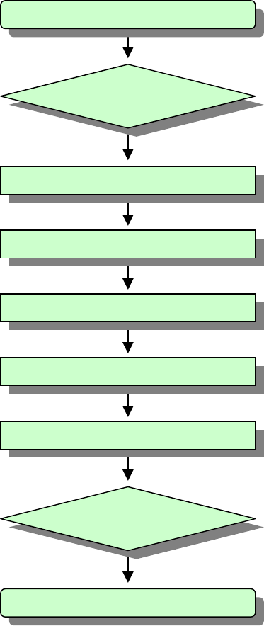
1. Installation Flow Chart
This document will provide details on how to successfully install the Juni JR-20 Repeater
system. The flow chart below provides a step by step guide for installing the JR-20 Repeater
Fig. 1 Installation Flow Chart
1. Start
3. Locating
4. Band Setting
5. DU
6. CU
7. Power / Optimization
9. End
8. Status Check
2. Package Check
8
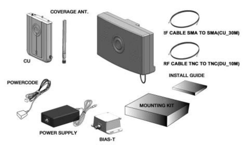
2. Component Verification and Explanation
The first step when installing the repeater is to check that all components are present and that the
parts do not have any visible faults. The figure below illustrates the items included in the Juni JR-
20 Repeater Kit.
Fig. 2 List of all the Components in the System
9
Fig. 3 Additional Coverage Unit Components
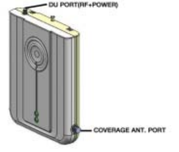
2.1 DONOR UNIT(DU)
The role of the Donor Unit is to communicate with the BTS. It is located outside the building
where service is to be improved. The Donor Unit can be mounted onto a wall or a pole,
depending on the specific installation needs.
Fig. 4 DONOR UNIT(DU)
10
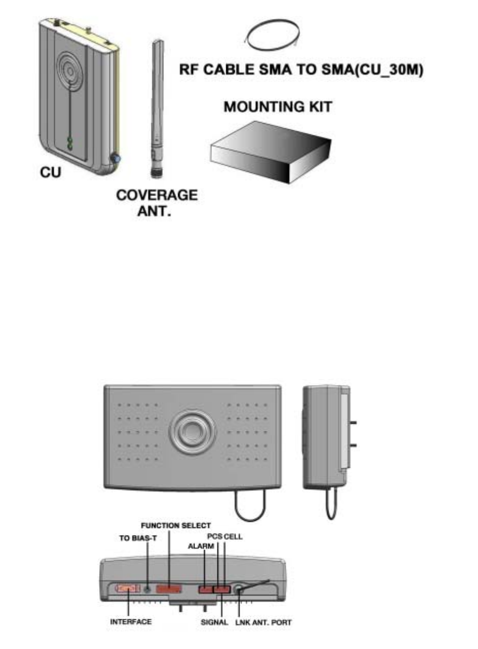
2.2 COVERAGE UNIT(CU)
The role of the Coverage Unit is to communicate with the mobiles within the building which
needs improved coverage. It is intended for wall mounting.
Fig. 5 Coverage Unit (CU)
3. Preparing for Donor Unit and Coverage Unit Installation
Determining the proper installation location for the Donor and Coverage Units is very important,
since their position will determine the overall performance of the repeater.
The authorized installer should determine where it will be mounted in accordance with the
instructions received by Juni for best reception by the BTS.
When determining the position of the Donor Unit, the following points should be considered.
Î Where is the target Donor BTS?
Î Will the Donor Unit be mounted on a wall or a pole? (99% will be wall mounted)
Î Try to avoid areas where may possibly hinder the communication between the Donor Unit
and the BTS such as large walls.
Î The Donor Unit should not be located any more than 10 feet away from the wall penetration
or window which will allow access to the inside of the building.
When determining the position of the Coverage Unit, the following points should be considered.
Î Try to position the Coverage Unit at the center of the desired indoor coverage area.
Î Try to position the Coverage Unit so that it is clearly visible throughout the desired indoor
coverage area.
Î Make sure that the distance from the Coverage Unit to the power source is less than 20 feet.
11
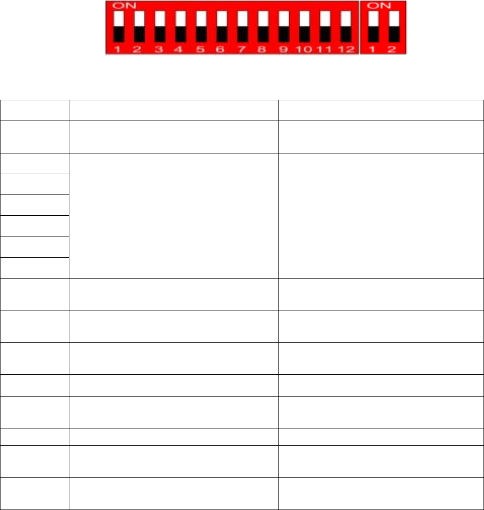
4. BAND SETTING
Once the planning of the location and positioning of the Donor and Coverage Units is finalized,
the authorized installer should proceed with installing the Donor and Coverage Units. But first,
the installer should set the appropriate frequency band(s) for the repeater. The figure and table
below show the DIP Switch and the functions for each section. Usually both the PCS and
Cellular bands have to be set up.
After DIP S/W setting, turn power ON/OFF or DIP S/W 12# PIN ON/OFF.
Î DIP Switch Functions
Fig. 6 DIP Switch General Settings
PIN NO. FUNC TION STATUS
1 Cellular Band Selection ON : Cellular B Band
OFF : Cellular A Band
2
3
4
5
6
7
PCS Band Selection See the next tables below
8 PCS EVDO OFFSET ON : PCS Gain OFFSET 3dB(increase) ON
OFF : PCS Gain OFFSET 3dB(reduction) OFF
9 Cellular EVDO OFFSET
ON : Cellular Gain OFFSET 3dB(increase )ON
OFF : Cellular Gain OFFSET 3dB(reduction) OFF
10 Band Selection Mode ON : Software Band Selection Mode
OFF : Hardware Band Selection Mode
11 Uplink RF OFF ON : Reverse RF Power OFF
OFF : Reverse RF Power ON
12 Hardware Reset ON : Reset
OFF : Normal Operation
PIN NO. FUNC TION STATUS
1 PCS PATH HARDWARE ON/OFF ON : PCS UL/DL PATH HARDWARE ON
OFF : PCS UL/DL PATH HARDWARE OFF
2 CELLULAR PATH HARDWARE ON/OFF ON : CELLULAR UL/DL PATH HARDWARE ON
OFF : CELLULAR UL/DL PATH HARDWARE OFF
12
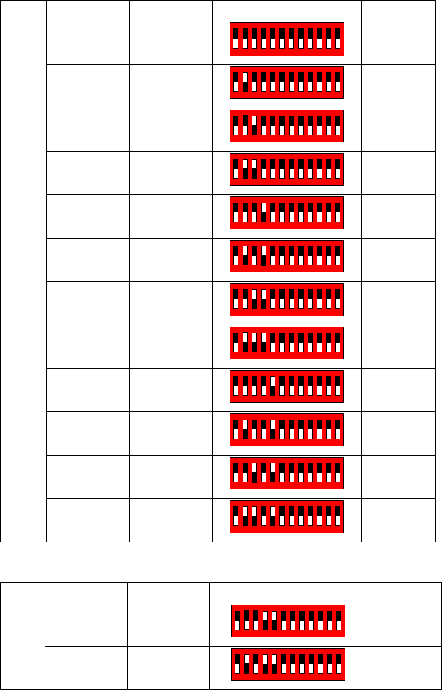
BW UP LINK DOWN LINK DIP SWITCH REMARK
1850 ~ 1855 1930 ~ 1935
123456789101112
ON
White color
is switch.
1855 ~ 1860 1935 ~ 1940
123456789101112
ON
1860 ~ 1865 1940 ~ 1945
123456789101112
ON
1865 ~ 1870 1945 ~ 1950
123456789101112
ON
1870 ~ 1875 1950 ~ 1955
123456789101112
ON
1875 ~ 1880 1955 ~ 1960
123456789101112
ON
1880 ~ 1885 1960 ~ 1965
123456789101112
ON
1885 ~ 1890 1965 ~ 1970
123456789101112
ON
1890 ~ 1895 1970 ~1975
123456789101112
ON
1895 ~ 1900 1975 ~ 1980
123456789101112
ON
1900 ~ 1905 1980 ~ 1985
123456789101112
ON
5MHz
1905 ~ 1910 1985 ~ 1990
123456789101112
ON
BW UP LINK DOWN LINK DIP SWITCH REMARK
1850 ~ 1860 1930 ~ 1940
123456789101112
ON
10MHz
1855 ~ 1865 1935 ~ 1945
123456789101112
ON
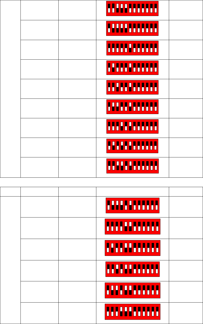
13
1860 ~ 1870 1940 ~ 1950
123456789101112
ON
1865 ~ 1875 1945 ~ 1955
123456789101112
ON
1870 ~ 1880 1950 ~ 1960
1 2 3 4 5 6 7 8 9 10 11 12
ON
1875 ~ 1885 1955 ~ 1965
1 2 3 4 5 6 7 8 9 10 11 12
ON
1880 ~ 1890 1960 ~ 1970
1 2 3 4 5 6 7 8 9 10 11 12
ON
1885 ~ 1895 1965 ~ 1975
1 2 3 4 5 6 7 8 9 10 11 12
ON
1890 ~ 1900 1970 ~ 1980
1 2 3 4 5 6 7 8 9 10 11 12
ON
1895 ~ 1905 1975 ~ 1985
1 2 3 4 5 6 7 8 9 10 11 12
ON
1900 ~ 1910 1980 ~ 1990
12345678 9101112
ON
BW UP LINK DOWN LINK DIP SWITCH REMARK
1850 ~ 1865 1930 ~ 1945
12 34 56 78 9101112
ON
1855 ~ 1870 1935 ~ 1950
12345678 9101112
ON
1860 ~ 1875 1940 ~ 1955
12345678 9101112
ON
1865 ~ 1880 1945 ~ 1960
12 34 56 78 9101112
ON
1870 ~ 1885 1950 ~ 1965
12345678 9101112
ON
15MHz
1875 ~ 1890 1955 ~ 1970
12345678 9101112
ON
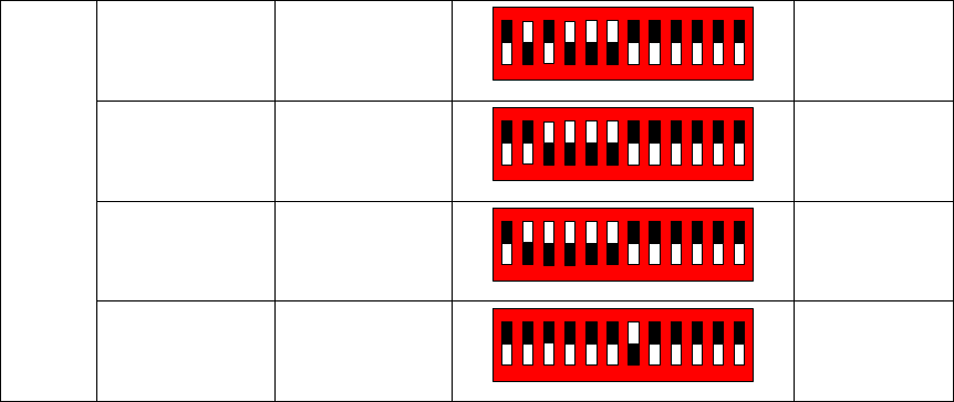
14
1880 ~ 1895 1960 ~ 1975
12345678 9101112
ON
1885 ~ 1900 1965 ~ 1980
12345678 9101112
ON
1890 ~ 1905 1970 ~ 1985
12345678 9101112
ON
1895 ~ 1910 1975 ~ 1990
12345678 9101112
ON
Table 1 Band Setting
15
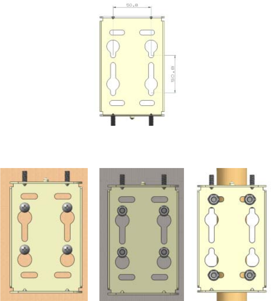
5. DONOR UNIT(DU) SET Installation
5.1 BRACKET-DU Image
5.1.1. DU 에 BRACKET – DU Connection Image
1) The length unit is [mm].
Fig. 7 MTG Bracket Image
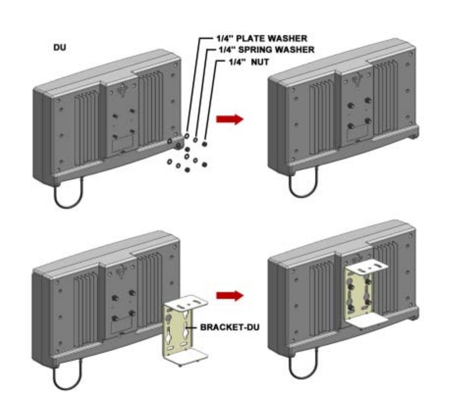
5.1.2. BRACKET-DU Connection Image to Installation(WALL or POLE)
( Pole Mounting ) ( Lumber Wall Mounting) ( Concrete Wall Mounting )
Fig. 8 MTG BRACKET Mounting (Pole, Lumber Wall, Concrete Wall) Connection Image
16
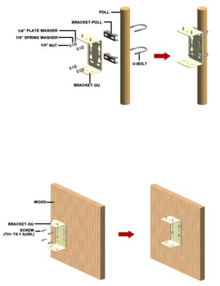
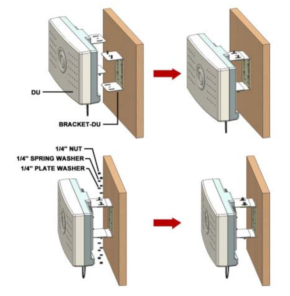
5.2 BRACKET Connection to DU
1) 1) APPLY NUT, SPRING WASHER, PLATE WASHER.
(Do not Connect Completely)
[NUT, SPRING WASHER, PLATE WASHER each 4ea]
2) Apply BRACKET/MTG to DU. APPLY NUT COMPLETELY USING PROVIDED TOOL.
[BRACKER/MTG 1ea]
Fig. 9 DU Bracket Connection Diagram
17
5.3 BRACKET Connection depending on Installation Place
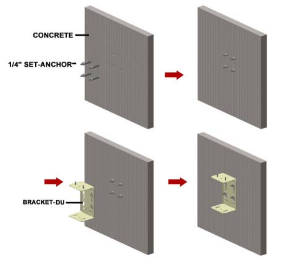
5.3.1. BRACKET/MTG POLE MOUNTING
1) Secure DU to the pole using U-BOLT.
2) Insert U-BOLT to between BRACKET-POLE and BRACKET-DU
3) Apply the pole to the BRACKET-DU: use the nuts and u-bolts provided to fixate the
bracket into the Pole.
[BRACKET-DU 1ea, BRACKET-POLE 2ea, U-Bolt 2ea, NUT, SPRING WASHER, PLATE
WASHER each 4ea]
Fig. 10 POLE MOUNTING MTG BRACKET-DU Connection Sequence
5.3.2. BRACKET/MTG LUMBER WALL Mounting
1) Secure BRACKET-DU to the wooden wall. Using cross driver connect SCREW to wooden
wall through BRACKET-DU.
[BRACKET-DU 1ea, SCREW 4ea]
Fig. 11 LUMBER WALL MOUNTING MTG BRACKET-DU Connection Sequence
18
5.3.3. BRACKET/MTG CONCRETE WALL Mounting
1) Drill on the wall as the BRACKET-ANT distance. (forφ 10mm Hole depth to be 30 to 40
mm.)
2) INSERT SET-ANCHOR TO DRILLED HOLE.
3) Secure BRACKET-DU to the Wall and fix the nut.
[BRACKER-DU 1ea, SET-ANCHOR 4ea]
Fig. 12 CONCRETE WALL MOUNTING MTG BRACKET-DU Connection Sequence
5.4 DU Connection (same as 5.1) with BRACKET(same as 5.2)
1) APPLY DU to the BRACKET.
2) Apply the NUT to the upside of BRACKET like below sequence. – Do not apply the NUT
19
completely.
3) Set the receiving direction of the ANTENNA and apply the NUT completely using the
provided tool.
[NUT, SPRING WASHER, PLATE WASHER each 4ea]
Fig. 13 DU Unit Wall Mounting
20
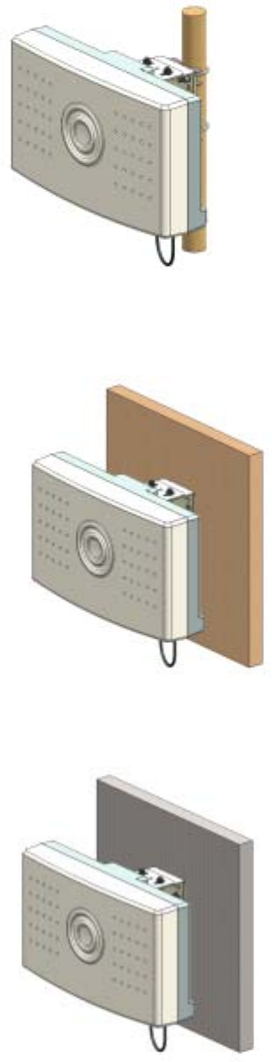
5.5 Installation Completion.
Fig. 14 DU Unit POLE Mounting Installation Completion Diagram
Fig. 15 DU Unit LUMBER WALL Mounting Installation Completion Diagram
Fig. 16 DU Unit CONCRETE WALL Mounting Installation Completion Diagram
21
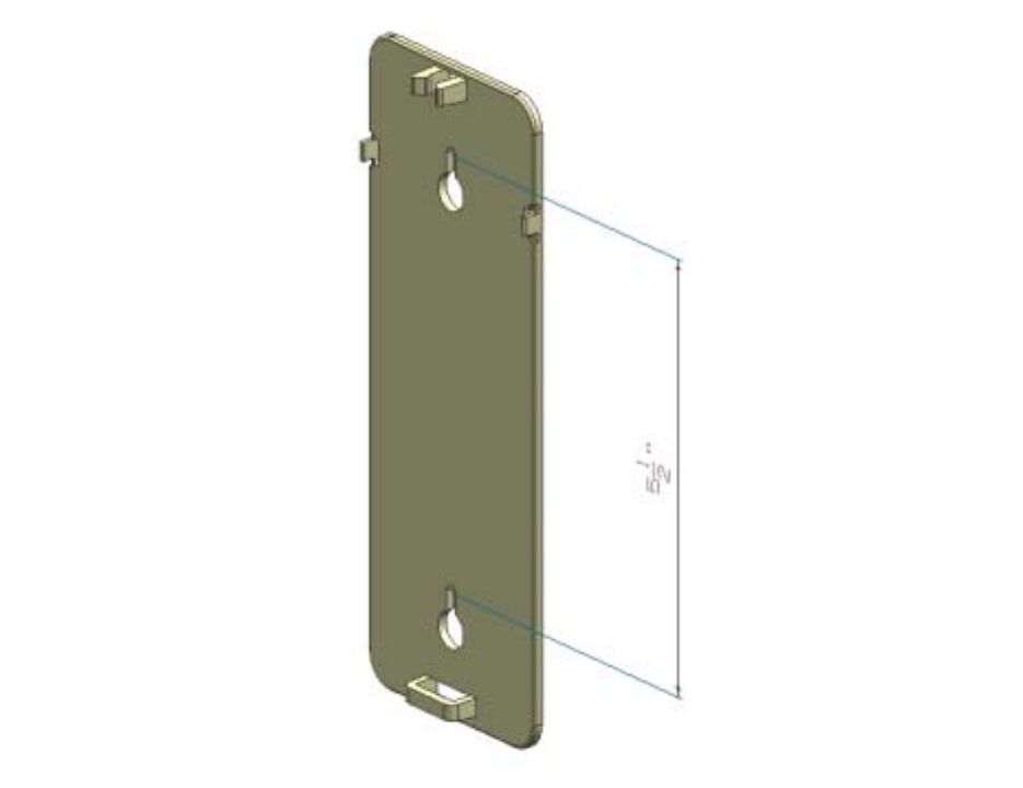
6. CU Wall & Ceil Mount Installation
6.1. MTG Bracket Image
Fig. 17 CU MTG Bracket Image & Hole Distance
22
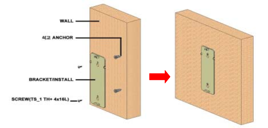
6.2 GYPSUM BOARD WALL MOUNTING
1) Secure DRYWALL anchor to the GYPSUM BOARD WALL using cross driver by keeping
BRACKET Hole distance 5.5inch(140mm).
2) Secure DRYWALL anchor screw(TS_1 TH+ 4x16L) to BRACKET/install.
Fig. 18 CU Bracket Gypsum Wall Mounting
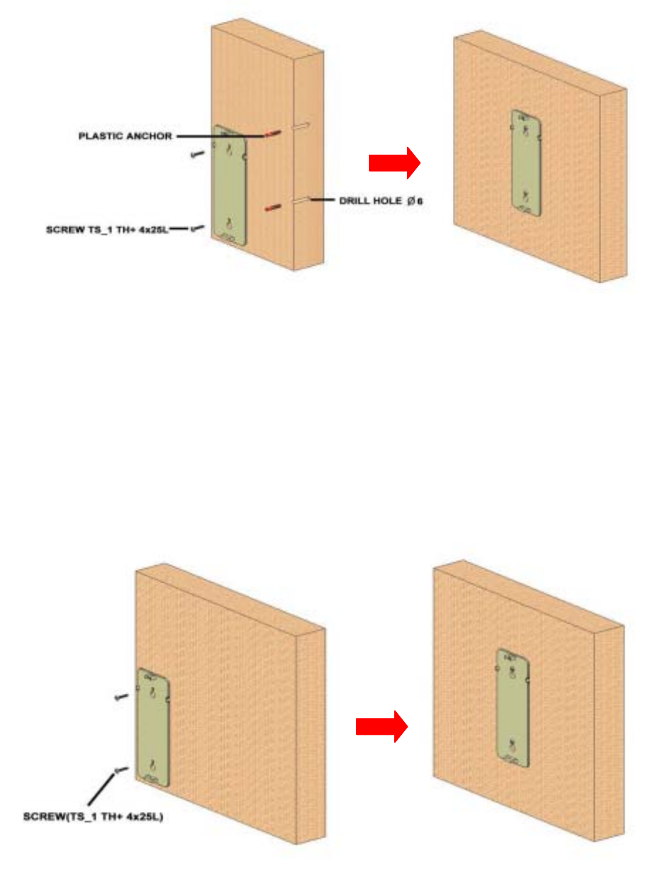
6.3 CONCRETE WALL MOUNTING
1) Secure PLASTIC ANCHOR TO WALL.
: INSERT PLASTIC ANCHOR after drill φ6mm Hole in the wall by 30~40mm depth by
keeping BRACKET Hole distance 5.5inch(140mm).
23
Fig. 19 CU Bracket Concrete Wall Mounting
6.4 LUMBER WALL MOUNTING
1) Secure BRACKET-INSTALL to the wooden wall. Using cross driver, connect completely
SCREW(TS_1 TH+ 4x25L) to wooden wall through BRACKET-INSTALL by keeping
BRACKET Hole distance 5.5inch(140mm).
Fig. 20 CU Bracket Lumber Wall Mounting
24
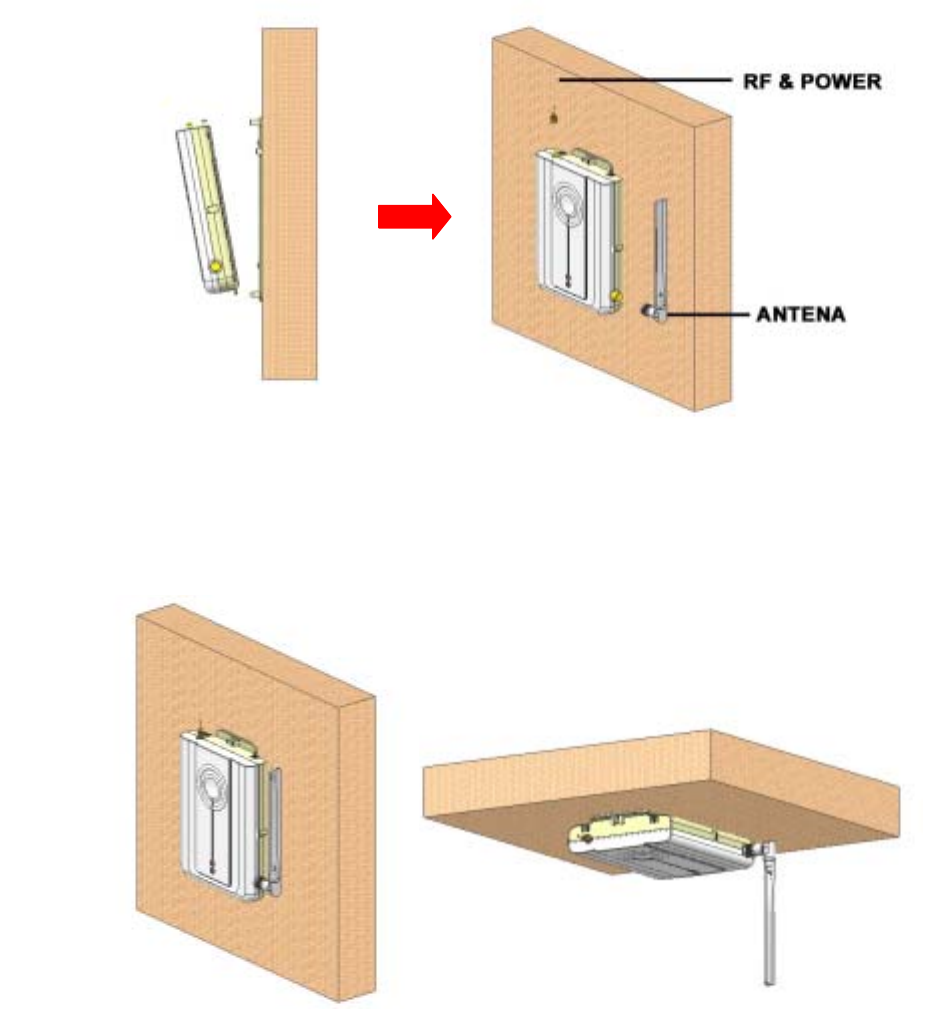
6.5 Install Bracket Connection with CU
1) APPLY CU to BRACKET-CU MTG.
2) After connecting RF+POWER CABLE, connect ANT to right TNC connector.
Fig. 21 CU MTG Bracket – CU SET Connection Image
6.6 CU SET Installation Completion
(WALL MOUNT) (CEIL MOUNT)
Fig. 22 CU Installation Sequence
25
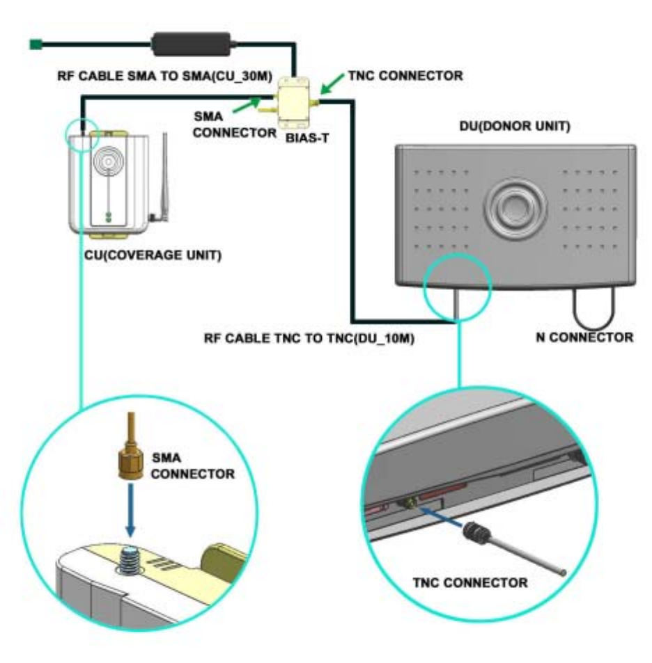
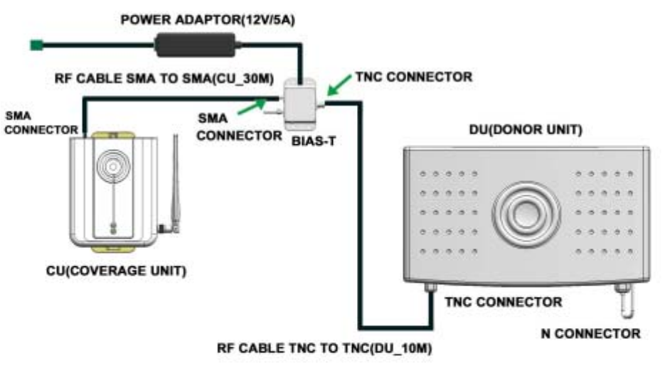
7. Power Connection and Optimization SETTING
1) Once the RF Cable is connected between the Donor Unit and Bias T and the second RF
Cable is connected between the Bias T and the Coverage Unit, the Power Adaptor should be
connected to the Bias T. If the Power Adaptor is connected to Bias T before the RF cable is
connected to either the Donor or Coverage Unit, possible damage could occur to the
equipment. Therefore the installer should be sure to connect the Power Adaptor to the Bias T
after the RF cables are connected to the Donor and Coverage Units.
Fig. 23 Power PORT Connection
26
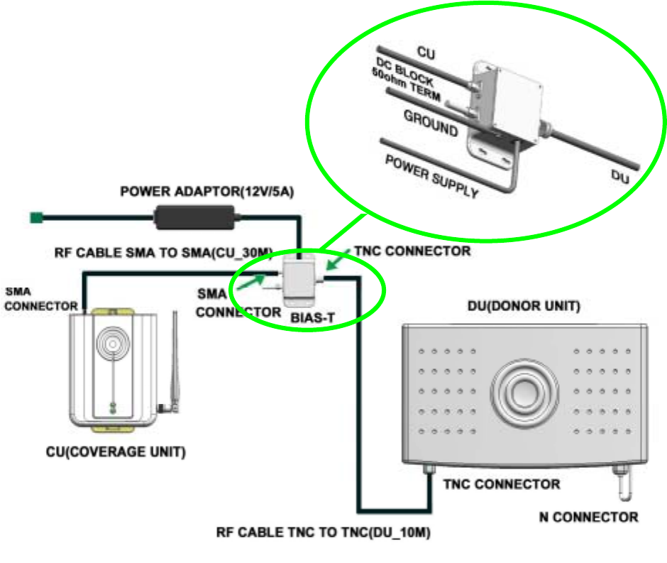
1-1) BIAS-T Installation Guide
. The figure below shows a detailed connection of the Power Adaptor and the Bias T. The
Ground cable at the Bias T must be connected before AC power is supplied to the Power
Adaptor.
Fig. 24 POWER INJECTOR Installation Diagram
27
2). Once power connection has been successfully made (this can be verified by checking the
Alarm LED on the Donor Unit and LED indications on the Coverage Unit, the Donor Unit azimuth
should be positioned so that maximum signal level is being received from the BTS. This can be
monitored via the LEDs which indicate the signal strength reading (RSSI).
(The recommended LED RSSI reading is 3 bars)
28
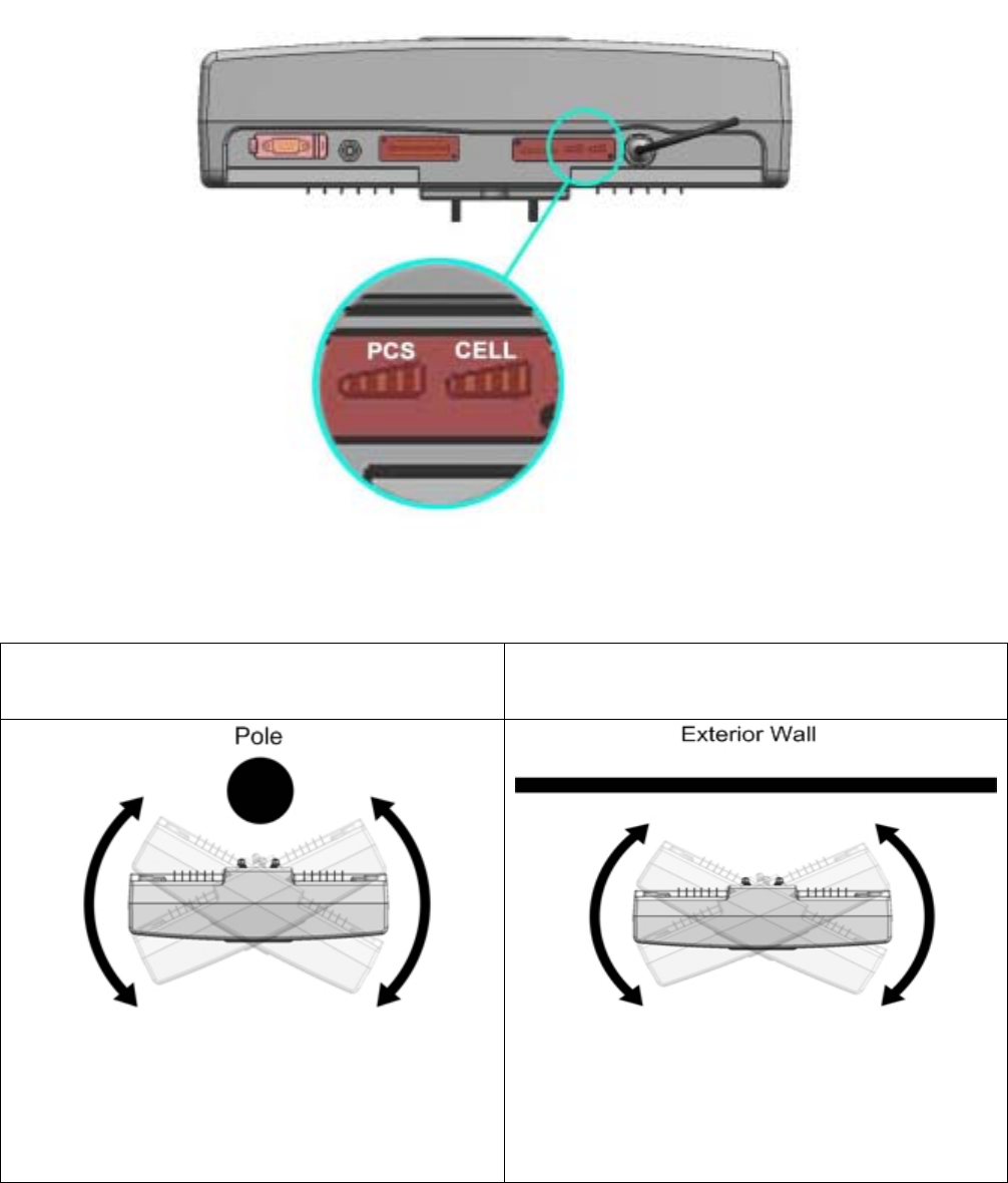
Outdoor DU on a Roof (Pole mount) Outdoor DU (Wall mount)
Once the Donor Unit is mounted onto the pole, it is
capable of being rotated 20° in either
direction. The Donor Unit can also be
mounted anywhere around the pole.
Can be rotated 20° in either direction
Fig. 25 DU ANT Tilt Diagram
3) The type of mounting method used will determine how much flexibility the Donor Unit has
to adjust the azimuth.
The diagram below shows how the installer can maneuver the Donor Unit to obtain the highest
29
signal strength while monitoring the LED indications.
Fig. 26 Verifying Reception Status Diagram
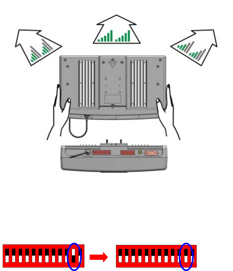
4) Once the positioning and direction of the Donor Unit has been finalized, use the DIP Switch
to activate the UL path.
1234567891011
1234567891011
Fig. 27 DIP Switch (Uplink Path Activation)
30
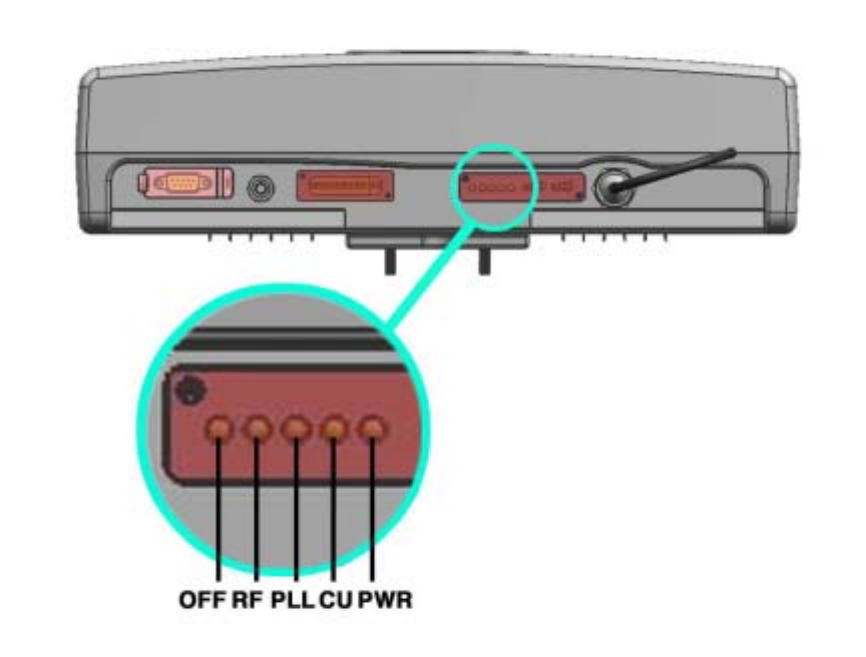
8. Status Check
8.1 DU FAULT LED
A red LED will turn on if the Repeater is not functioning properly. Each of the LEDs pertains
to the status of a specific section of the system as shown below.
Fig. 28 DU LED
▶ MANUAL OFF – If the installer decides to turn off the system, this LED will indicate red.
▶ RF – If the output power level exceeds the preset limit or if oscillation is present, the
Repeater will automatically shut down and the RF LED will indicate RED.
▶ PLL – Malfunction of the frequency setting circuitry will cause this LED to indicate RED.
▶ CU – Malfunction of the Coverage Unit will cause this LED to indicate RED.
▶ POWER – If the input RF level is not within the range set by the installer, or if the system
identifies a problem during operation, this LED will indicate RED.
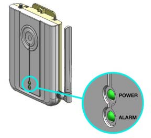
8.2 CU FAULT LED
A red LED will indicate that the equipment is not functioning properly. Each of the LEDs
DU(DONOR UNIT)
31
represents a specific section of the system as shown below.
Fig. 29 CU LED
▶ POWER – Will indicate GREEN if power is being supplied to the Unit
▶ ALARM – If the RF input level is not within the range set by the installer, or if the system
identifies a problem during operation, this LED will indicate RED.
CU(COVERAGE UNIT)
32
Appendix A. Product Introduction
A.1 Overview
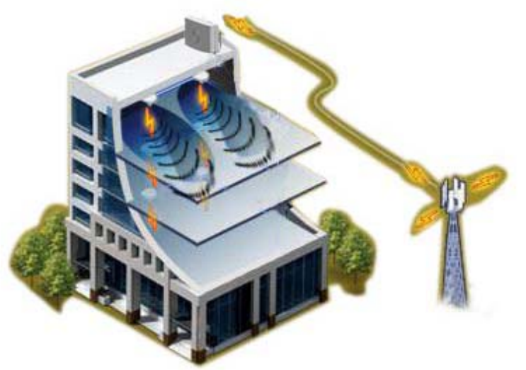
The Juni JR-20 MPE25K Repeater system is an RF repeater which provides coverage for
indoor locations within a BTS coverage area. The repeater is intended to serve indoor
locations where there is very little or no RF coverage. The system supports both US Cellular
and US PCS bands. Verizon Wireless-authorized installation personnel are able select to
frequency bands of operation via the internal band selection function. The Juni JR-20
MPE25K Repeater is intended to suit indoor environments of up to 25,000 sq.ft. The system
configuration includes a Donor Unit which is typically located outside the building and a
Coverage Unit which is positioned at the approximate center of the indoor space requiring
better coverage. The role of the Donor Unit is to provide the link between the repeater system
and the BTS. The Coverage Unit is intended to communicate with Mobiles located indoors.
An optional second Coverage Unit may be added to the system to enhance indoor coverage.
Fig. 30 System Installation
33
The diagram below shows the basic system configuration. Once the two supplied RF Cables
are connected from the Bias-T to the Donor Unit and Coverage Unit respectively and the
Power Adaptor is connected to the Bias T with AC Power turned on, the Donor Units and
Coverage Unit(s) will function properly.
Fig. 31 System Diagram
34
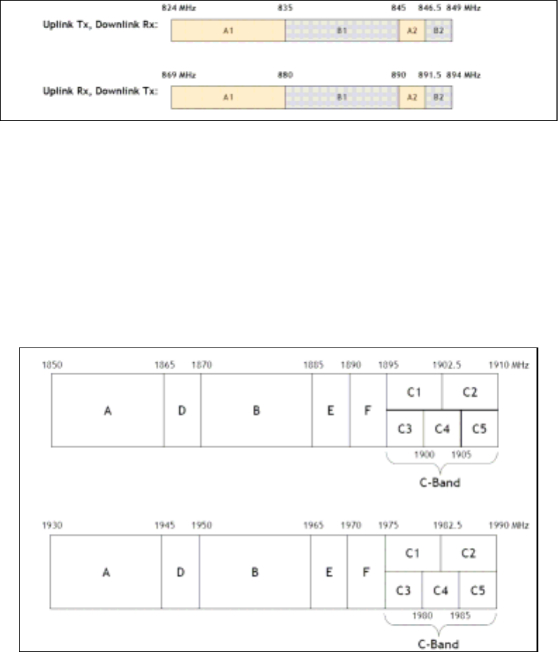
A.2 Supported Frequency Range
▶ Operator : Verizon Wireless
▶ Frequency Band in Use : CELLULAR or PCS
Î CELLULAR Frequency Range
Î Cellular Band: (B1 and B2) or (A1 and A2) depending on Verizon Wireless’ Cellular Band
license for the area where the repeater is to be installed.
Table 2 Cellular Frequency
Î PCS Frequency Range (1850-1990 MHz): 1 tunable, non-contiguous PCS band of 5, 10
or 15 MHz selected depending on Verizon Wireless’ PCS band license for the area where the
repeater is to be installed.
Table 3 PCS Frequency
35
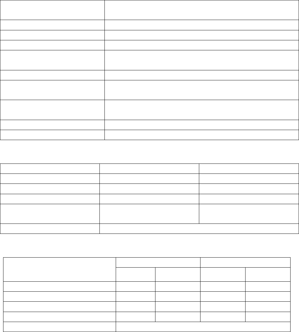
Appendix B. System Specifications
Frequency Bands PCS Uplink : 1850 – 1910MHz Downlink : 1930 – 1990MHz
CELL Uplink : 824 – 849MHz Downlink : 869-894 MHz
Sub-Bands Cell : A+A’, B+B’ PCS : 5 , 10 , 15 MHz
Formats Supported IS-95 / CDMA / 1X EVDO
Typical Coverage Area 2,5000 sq. ft(230 ㎡)
System Gain(Eirp) CEL Up link : 79dB , CEL Down link : 82dB
PCS Up link : 85dB , PCS Down link : 88dB
Downlink Operating Range ~ -40dBm (Receive isotropic power)
Output Level(MAX Eirp) CEL UPLINK : +20dBm, CEL DOWNLINK : +12dBm
PCS UPLINK : +20dBm, PCS DOWNLINK : +18dBm
Third Order Intercept(Eirp)
- typical
CEL DL : 36dBm , CEL UL : 43dBm
PCS DL :38dBm , PCS UL : 38dBm
Power Consumption < 60W
부가 기능 AGC FUCNTION, BRING DOWN, OVERDRIVE, OVERPOWER
Table 4 RF Specifications
DONOR UNIT COVERAGE UNIT
OPERATING TEMPERATURE -20 ℃ ~ 50 ℃ 0 ℃ ~ 40 ℃
SIZE 389(W) X 236(H) X 107(D) 144(W) X 190(H) X 38(D)
WEIGHT 2.7Kg 0.5Kg
RF CONNECTORS LINK : N TYPE
CU : TNC TYPE
DU ANT : SMA
COVERAGE ANT : TNC TYPE
POWER SUPPLY < 60W
Table 5 Physical Specifications
CELL PCS
DU ANT CU ANT DU ANT CU ANT
GAIN(dBi) 10 0 10 0
Elevation Beamwidth-typical(dg) 65° >90° 50° >90°
Azimuth Beamwidth-typical(dg) 40° NA 30° NA
Front-to-Back Ratio(dB) > 15dB NA > 15dB NA
Polarization Vertical
Table 6 Antenna Specifications
36
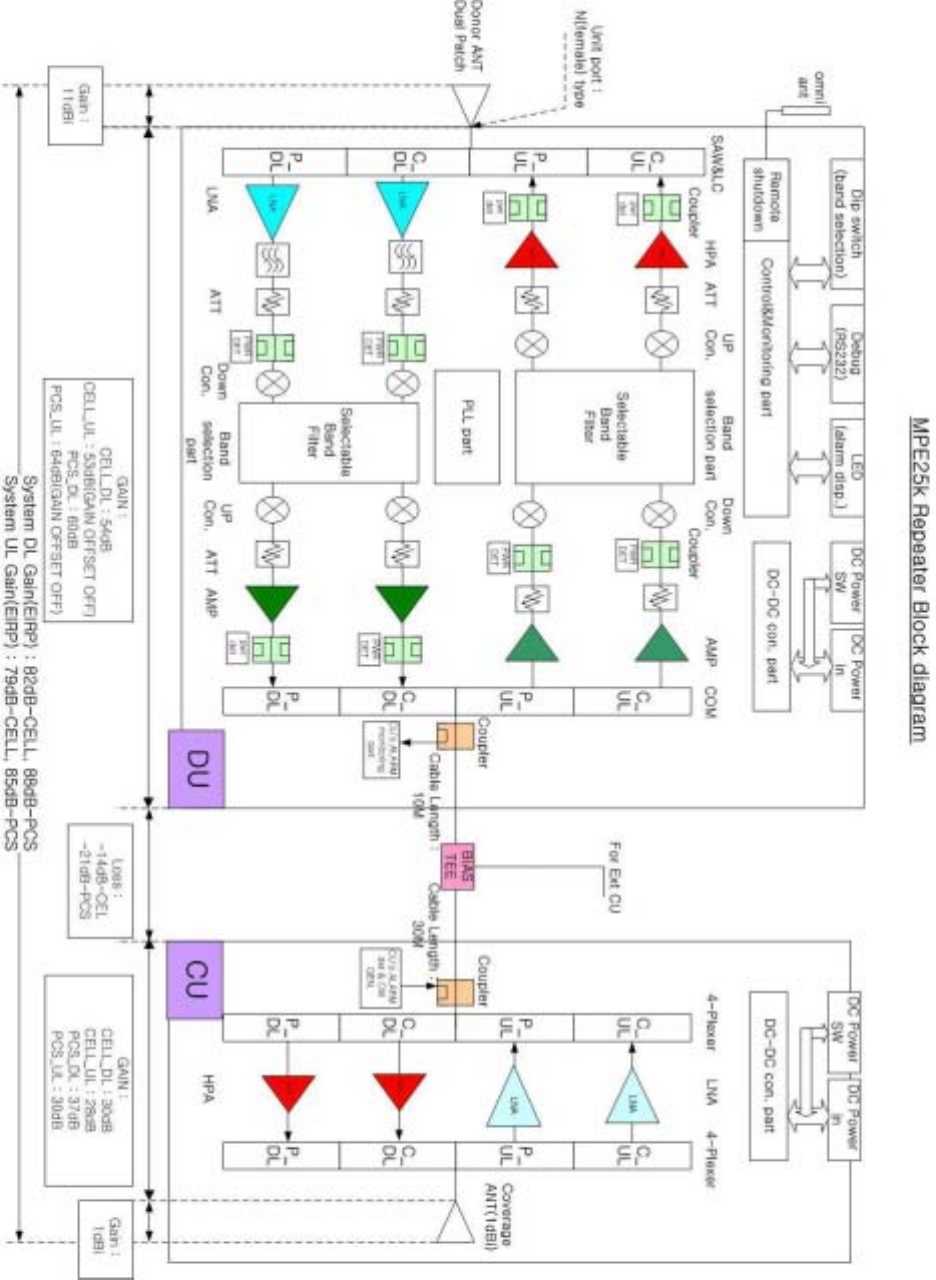
Appendix C. System Block

37
Appendix D. Troubleshooting for MPE25K
DU
Alarm LED Color Possible Reason Action Required Action
MANUAL
OFF
Green
-> Red
When service Provider
force the System OFF
Check Alarm
-> Call Juni Technical Support
RF Green
-> Red
Shutdown by
Excessive RF Output
Power or System
Oscillation
- Excessive Output Power:
Automatically Recovered. Call Juni
Technical Support if repeated
- Oscillation: Wrong Donor Unit
direction or Donora Unit and
Coverage Unit installed too close to
one another
Call Juni Technical Support if not
improved
PLL Green
-> Red Repeater Failure
Check Alarm
-> Power ON/OFF
Call Juni Technical Support if not
improved
CU Green
-> Red
COVERAGE UNIT- Out
of Service
Check Alarm
-> Check the Input AC/DC Power
Adaptor
-> Call Juni Technical Support if
not improved
Power Green
-> Red
Input Power – Out of
Range
Operating Current –
Out of Range
Check Alarm
-> Check the Input AC/DC Power
Adaptor
-> Call Juni Technical Support if
not improved
Contact
Juni
Technical
Support
1. Coverage Unit
Alarm LED Color Possible Reason Action Required Action
CU Green
-> Red
COVERAGE UNIT- Out
of Service
Check Alarm
-> Check input AC/DC Power
-> Call Juni Technical Support
Call Juni
Technical
Support
38