Inmarsat Solutions GLOBEI250BDE Martime Satellite Voice & Data Router User Manual
Inmarsat Solutions (US) Inc. Martime Satellite Voice & Data Router
User Manual

May 2010
IG266 Rev A
Issued by Globe Wireless, Inc.
1571 Robert J. Conlan Blvd. NE Palm Bay, FL 32905Printed in U.S.A.
Globe Wireless Installation
Guide IG 266
Installing a Globe i250
Every effort has been made to ensure that the information contained herein is complete and accurate;
however, information contained in this manual is subject to change without notice and Globe Wireless®
reserves the right to change specifications of hardware and software without prior notice. Globe
Wireless® obligations regarding the use or application of its products shall be limited to those
commitments to the purchaser set forth in its Standard Terms and Conditions of Sale for a delivered
product.
© Copyright 2008, Globe Wireless, Inc®. All rights reserved. This document contains information
Confidential and Proprietary to Globe Wireless®. No part of this publication may be reproduced or
transmitted by any means and disclosure or distribution of its contents for any purpose without written
consent from Globe Wireless® is strictly prohibited.
May 2010
IG266 Rev A
Issued by Globe Wireless, Inc.
1571 Robert J. Conlan Blvd. NE Palm Bay, FL 32905Printed in U.S.A.
Globe Wireless Installation Guide
IG 266 Revision Page
Rev By Description of Changes Date
A WD Initial Release of Installation Guide (ECO 1068) 5/27/2010
Document Approval
Title Name Date Doc. Rev.
Engineering A
Product Management A
Peer Review A
QUALITY Dan Thomasson A

May 2010
IG266 Rev A
Globe Wireless Installation Guide – IG266 Rev A iii
This page intentionally left blank.

May 2010
IG266 Rev A
Globe Wireless Installation Guide – IG266 Rev A iv
Table of Contents
1.0Regulatory Information ................................................................................................... 1-1
1.1Federal Communication Commission Notice ................................................................. 1-1
1.2Eu Declaration of Conformity: ........................................................................................ 1-2
2.0Warning Safety Information ............................................................................................ 2-1
2.1Observe marked areas ................................................................................................... 2-1
2.1.1Microwave radiation hazards .................................................................................. 2-1
2.1.2Distance to other equipment ................................................................................... 2-1
2.1.3Service .................................................................................................................... 2-2
2.1.4Do not service or adjust alone ................................................................................ 2-2
2.1.5Grounding, cables and connections ....................................................................... 2-2
2.1.6Power supply .......................................................................................................... 2-2
2.1.7Equipment ventilation .............................................................................................. 2-2
2.1.8Keep away from live circuits ................................................................................... 2-3
2.1.9Obtaining Licensing For Inmarsat Terminals .......................................................... 2-3
3.0General Information ......................................................................................................... 3-1
3.1Overview ........................................................................................................................ 3-1
3.2Installation Guide Organization ...................................................................................... 3-1
3.3Special Notations ........................................................................................................... 3-1
3.4Customer Comments and Quality .................................................................................. 3-2
3.5General Safety Reminders ............................................................................................. 3-2
3.6Additional Equipment Needed ....................................................................................... 3-3
3.7Available Services .......................................................................................................... 3-3
4.0Hardware and Software Requirements .......................................................................... 4-1
4.1Components ................................................................................................................... 4-1
4.2Equipment Configuration ................................................................................................ 4-1
4.2.1Globe i250 Front View ............................................................................................ 4-1

May 2010
IG266 Rev A
Globe Wireless Installation Guide – IG266 Rev A v
4.2.2Globe i250 Rear View ............................................................................................. 4-2
4.3Preparation ..................................................................................................................... 4-2
4.3.1Installing the Globe i250 into 19” High Profile Rack Cabinet.................................. 4-3
4.3.2Installing the Globe i250 onto Wall, Shelf or Table ................................................ 4-3
4.3.3Installing the ADE ................................................................................................... 4-4
4.3.4Installing the SIM Card............................................................................................ 4-6
5.0Setup Instructions ........................................................................................................... 5-1
5.1LAN setup for communication on Shipboard Network ................................................... 5-1
5.2Satellite Search .............................................................................................................. 5-2
5.3Initiating a Data Connection ........................................................................................... 5-3
5.4Making Voice Calls ......................................................................................................... 5-4
5.4.1Voice Connections using the Handset .................................................................... 5-4

May 2010
IG266 Rev A
Globe Wireless Installation Guide – IG266 Rev A 1-1
1.0 Regulatory Information
1.1 Federal Communication Commission Notice
FCC Identifier: YC6-GLOBEI250BDE
USE CONDITIONS:
This device complies with part 15 of the FCC Rules. Operation is subject to the following two
Conditions:
1. This device may not cause harmful interference.
2. This device must accept any interference received, including interference that may cause
undesired operation.
NOTE:
This equipment has been tested and found to comply with the limits for a Class B digital device,
pursuant to Part 15 of the FCC Rules. These limits are designed to provide reasonable protection
against harmful interference in a residential installation. This equipment generates uses and can
radiate radio frequency energy and, if not installed and used in accordance with the instructions,
may cause harmful interference to radio communications. However, there is no guarantee that
interference will not occur in a particular installation.
If this equipment does cause harmful interference to radio or television reception, which can be
determined by turning the equipment off and on, the user is encouraged to try to correct the
interference by one of the following measures:
Reorient or relocate the receiving antenna
Increase the separation between the equipment and receiver
Connect the equipment into an outlet on a circuit different from that to which the receiver is
connected
Consult the dealer or an experienced radio/TV technician for help
IMPORTANT NOTE: EXPOSURE TO RADIO FREQUENCY RADIATION
This Device complies with FCC & IC radiation exposure limits set forth for an uncontrolled
environment. The Antenna used for this transmitter must be installed to provide a separation
distance of at least 100cm from all persons and must not be co-located or operating in conjunction
with any other antenna or transmitter

May 2010
IG266 Rev A
Globe Wireless Installation Guide – IG266 Rev A 1-2
FCC CAUTION:
Any Changes or modifications not expressly approved by the manufacturer could void the user's
authority, which is granted by FCC, to operate this Maritime Satellite Voice and Data Router
1.2 Eu Declaration of Conformity:
Globe wireless LLC, 1571 Robert J. Conlan Blvd. Palm Bay, FL 32905 declares under our sole
responsibility that the Product, brand name as Globe wireless and model: Globe i250 Maritime
Satellite Voice and Data Router, to which this declaration relates, is in conformity with the following
standards and/or other normative documents:
ETSIEN301444V1.1.1:2000
ETSIEN301489‐1V1.8.1:2008
ETSIEN301489‐20V1.2.1:2002
EN61000‐3‐2:2006(CLASSA)
EN61000‐3‐3:1995+A1:2001+A2:2005
EN60945:2002
EN60950‐1:2001+A11:2004
We hereby declare that all essential radio test suites have been carried out and that the above
named product is in conformity to all the essential requirements of Directive 1999/5/EC.
The Conformity Assessment procedure referred to Article 10 and detailed in Annex [III] or [IV] of
Directive 1999/5/EC has been followed with involvement of the following notified body(ies):
TIMCO ENGINEERING, INC., P.O BOX 370, NEW BERRY, FLORIDA 32669.
Identification mark: 1177 (Notified Body number)
The technical documentation relevant to the above equipment is held at:
Addvalue Communications Pte Ltd, 28 Tai Seng Street , #06-02, Singapore 534106
Signed by Mr. Mark Witsaman, Chief Technical Officer
on 17th May 2010

May 2010
IG266 Rev A
Globe Wireless Installation Guide – IG266 Rev A 2-1
2.0 Warning Safety Information
WARNING! It is imperative that you read the following information in its entirety and
understand it fully prior to continuing.
For your safety and protection, read this entire user manual before you attempt to use the Globe
i250 System. In particular, read this safety section carefully. Keep this safety information where
you can refer to it if necessary.
The following general safety precautions must be observed during all phases of operation, service
and repair of this equipment. Failure to comply with these precautions or with specific warnings
elsewhere in this manual violates safety standards of design, manufacture and intended use of the
equipment.
Globe Wireless assumes no liability for the customer's failure to comply with these requirements.
2.1 Observe marked areas
Under extreme heat conditions do not touch areas of the terminal or antenna that are marked with
this symbol, as it may result in injury.
2.1.1 Microwave radiation hazards
During transmission the antenna in this system radiates Microwave Power. This radiation may be
hazardous to humans close to the antenna. During transmission, make sure that nobody gets
closer than the recommended minimum safety distance.
On the Globe i250 System, the minimum safety distance on the focal line to the antenna panel is
0.6 m, based on a radiation level of 10 W/m2. The radiation level is 100 W/m2 at a distance of 0.2
m from the antenna panel.
2.1.2 Distance to other equipment
Do not move the antenna closer to radars than the minimum safe distance specified in the
installation manual - it may cause damage to the antenna. The equipment must be installed with
the following minimum safe distances to magnetic steering compass:
i250 FleetBroadband antenna: min. 1.1 m
i250 FleetBroadband terminal: min. 0.3 m.

May 2010
IG266 Rev A
Globe Wireless Installation Guide – IG266 Rev A 2-2
2.1.3 Service
User access to the interior of the terminal is prohibited. Only a technician authorized by Globe
Wireless may perform service - failure to comply with this rule will void the warranty. Access to the
interior of the antenna is allowed, but only for replacement of certain modules - as described in the
Installation manual. General service must be performed only by an authorized technician.
2.1.4 Do not service or adjust alone
Do not attempt internal service or adjustments unless another person, capable of rendering first aid
resuscitation, is present.
2.1.5 Grounding, cables and connections
To minimize shock hazard, the equipment chassis and cabinet must be connected to an electrical
ground. Both terminal and antenna must be grounded to the ship. For further grounding information
refer to the Installation manual.
Do not extend the cables beyond the lengths specified for the equipment.
The cable between the terminal and antenna can be extended if it complies with the specified data
concerning cable losses etc.
All cables for the Globe i250 system are shielded and should not be affected by magnetic fields.
However, try to avoid running cables parallel to AC wiring as it might cause malfunction of the
equipment.
2.1.6 Power supply
The voltage range is 85-264 VAC. Two sets of fuses are provided with the i250. If using 110V
nominal voltage use the 6.3 A fuse. If the nominal voltage is 220V use the 3.6 A fuse. Globe
Wireless recommends the use of a UPS system for improved reliability.
2.1.7 Equipment ventilation
To ensure adequate cooling of the terminal, make sure that the side ventilation areas are
free of obstruction
The ambient temperature range of the terminal is: -25° to +55°C
Do not operate in an explosive atmosphere
Do not operate the equipment in the presence of flammable gases or fumes
Operation of any electrical equipment in such an environment constitutes a definite safety
hazard

May 2010
IG266 Rev A
Globe Wireless Installation Guide – IG266 Rev A 2-3
2.1.8 Keep away from live circuits
Operating personnel must not remove equipment covers. Component replacement and internal
adjustment must be made by qualified maintenance personnel. Do not replace components with
the power cable connected. Under certain conditions, dangerous voltages may exist even with the
power cable removed. To avoid injuries, always disconnect power and discharge circuits before
touching them.
2.1.9 Obtaining Licensing For Inmarsat Terminals
Under rights given under ITU Radio Regulations, local telecommunications administrations
establish and enforce national rules and regulations governing types of emissions, power levels,
and other parameters that affect the purity of signal, which may be radiated in the various
frequency bands of the radio spectrum.
To legally operate Inmarsat equipment, it is necessary to obtain permission from the local
telecommunications regulatory authorities of the country you are operating from. Using your
equipment in any country without permission causes you to run the risk of confiscation of the
equipment by the local authorities. The normal procedure to bring such equipment into another
country is to apply for a license before travel. If a license has not been obtained before travel, the
equipment may be put in to storage by local authorities until such time license is obtained.
WARNING! Failure to comply with the rules above will void the warranty!
Release date: May 2010
Information in this document is subject to change without notice and does not represent a
commitment on the part of Globe Wireless.
Copyright © 2010 Globe Wireless. All rights reserved.
For further assistance, contact the Globe Wireless Customer Service Center at:
Within the United States or Canada: 1-(877)-535-0653
Overseas: 1-(321)-308-0112
customerservice@globewireless.com
www.globewireless.com

May 2010
IG266 Rev A
Globe Wireless Installation Guide – IG266 Rev A 2-4
This page intentionally left blank

May 2010
IG266 Rev A
Globe Wireless Installation Guide – IG266 Rev A 3-1
3.0 General Information
3.1 Overview
The purpose of this document is to provide the procedures for installing a Globe i250 system.
3.2 Installation Guide Organization
This installation guide is divided into several sections providing specific information needed to
install and verify operation of the Globe i250 System:
Section 1: Regulatory Information – Contains all regulatory usage information,
FCC Identifier, and important notifications, warnings and cautions.
Section 2: Warning Safety Information – Safety warning which must be read prior
to proceeding with handling or installation of the Globe i250.
Section 3: General Information - Contains a general overview and description of
special notations used throughout this guide. Discusses necessary
components and additional equipment, as well as, available services and
reference documentation.
Section 4: Hardware and Software Requirements - Contains information on
HW/SW requirements necessary for installation, and provides a
configuration drawing. Discusses how the installer is to prepare for the
installation, and walks the installer through the SIM card installation.
Section 5: Setup Instructions - Setting up the connections for Internet Browsing,
SMS messaging, Fax, etc. Shows the installer how to ascertain the
system is set up properly.
3.3 Special Notations
This installation guide uses the following levels of special notation to alert the installer to important
information concerning safety, proper equipment handling, or useful tips for easier operation.
These notations are shown below in descending order of importance:
DANGER! Indicates that personal injury can result if there is a failure to comply with the given
instructions. A DANGER! statement will describe the potential hazard, its possible
consequences, and the steps to avoid personal injury.
WARNING! Indicates that serious damage to the equipment can result if there is a failure to
comply with the given instructions. A WARNING! statement will describe the
potential hazard, its possible consequences, and the steps to avoid serious
equipment damage.

May 2010
IG266 Rev A
Globe Wireless Installation Guide – IG266 Rev A 3-2
CAUTION! Indicates that equipment damage and/or process failure can result if there is a
failure to comply with the given instructions. A CAUTION! statement will describe
the potential hazard, its possible consequences, and the steps to avoid equipment
damage and/or process failure.
NOTE: Provides supplementary information to emphasize a point or procedure, or gives a
tip for easier operation.
3.4 Customer Comments and Quality
Globe Wireless is ISO Certified, and committed to quality and total customer satisfaction.
Comments are important to us and help us to provide quality products and services. We invite
emails from satisfied customers as well as comments and recommendations for improvement.
Email comments and suggestions to: quality@globewireless.com
3.5 General Safety Reminders
To prevent possible personal injury or equipment damage, always observe the following rules:
Installation personnel should be familiar with the safety requirements before attempting
installation of the equipment covered in this installation guide. Failure to follow the
requirements could result in death or injury to personnel and/or damage to the equipment.
Always examine the general area for potential hazards before beginning installation.
Observe all DANGER notations. Dangerously high voltages are present within the
equipment when in operation. Lethal line voltages may be present unless the power has
been disconnected.
Observe grounding precautions. Verify the unit being installed and all measurement
equipment is properly grounded.
May 2010
IG266 Rev A
Globe Wireless Installation Guide – IG266 Rev A 3-3
3.6 Additional Equipment Needed
Refer to the following table for additional equipment that will be needed for installation:
Equipment Type Globe Wireless Part Number
Broadband SIM Card 73-02337-0014
Side Mount Antenna Clamp 54-01954-0002
Pole Mount 51-03557-0004
Ground Strap 01-02156-0002
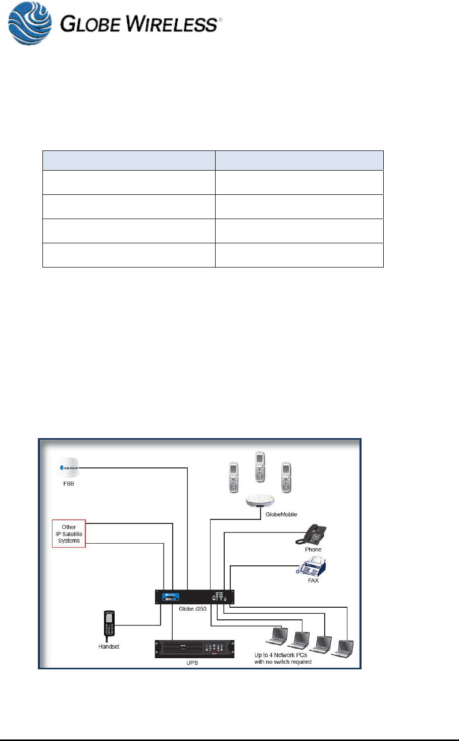
3.7 Available Services
This unit supports the following services:
Simultaneous voice and data over FleetBroadband
Full duplex, single or multi-user, up to 284kbps
Support for streaming IP at: 32, 64, 128 kbps
Standard Voice (AMBE+2, 4.0 kbps)
Fax/High Quality Voice (64kbps, A-law PCM)

May 2010
IG266 Rev A
Globe Wireless Installation Guide – IG266 Rev A 3-4
This page intentionally left blank.
May 2010
IG266 Rev A
Globe Wireless Installation Guide – IG266 Rev A 4-1
4.0 Hardware and Software Requirements
4.1 Components
The following equipment, software and tools are required prior to installation:
IBM compatible 1GB or faster PC
Globe i250
FleetBroadband Class 9 ADE
FleetBroadband SIM Card
Miscellaneous Cables
4.2 Equipment Configuration
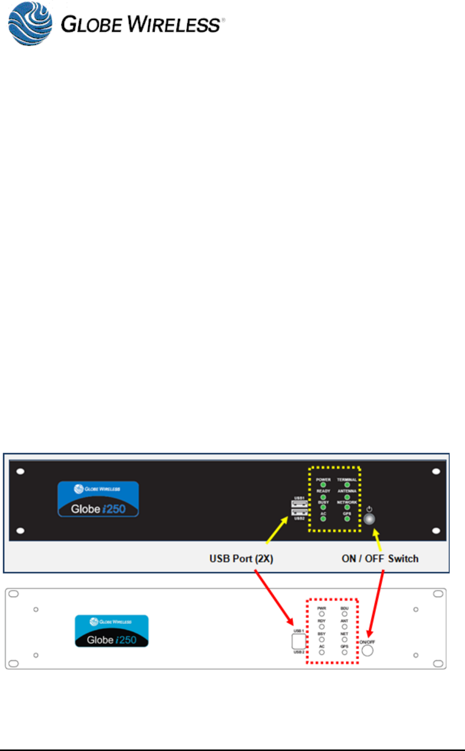
4.2.1 Globe i250 Front View
The front view (two views shown below) of the Globe i250 consists of two USB Ports, and On/Off
Switch, and the following led’s:
Power
Ready
Busy
AC
Terminal
Antenna
Network
GPS
May 2010
IG266 Rev A
Globe Wireless Installation Guide – IG266 Rev A 4-2
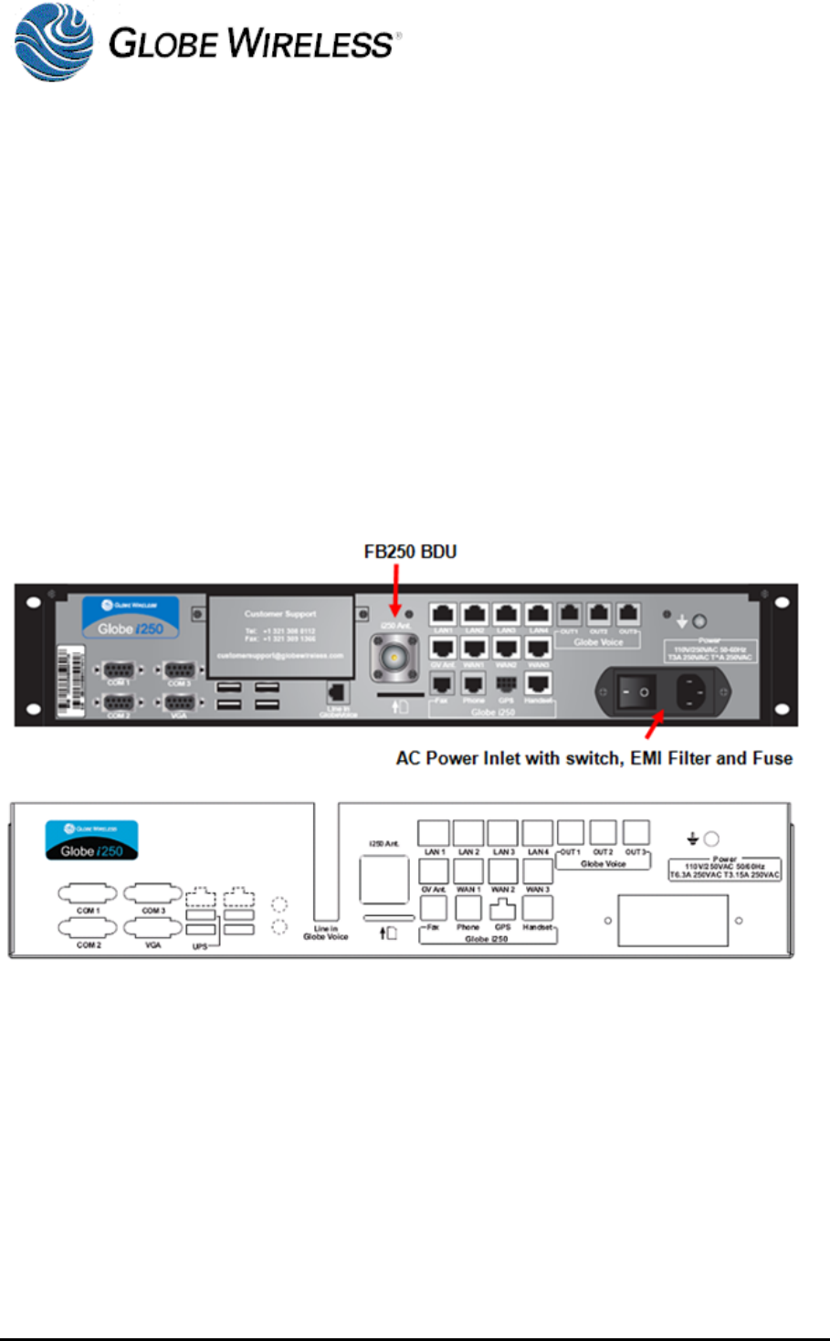
4.2.2 Globe i250 Rear View
The rear view (two views shown below) of the Globe i250 consists of the following:
1 X IEC AC power input 100-240 VAC
1 X Type N Antenna connection
2 X RJ11 POTS handset and FAX
3 X RJ11 Voice Out connections
3 X RJ45 WAN Ethernet connections
1 X RJ45 PoE BTS connection
4 X RJ45 LAN Ethernet connections
4 X USB ports
3 X 9 pin D RS-232
4.3 Preparation
The Globe i250 is to be installed onboard ship in a control room into a Rack Cabinet or by
mounting on the wall, shelf, or table as described below.
May 2010
IG266 Rev A
Globe Wireless Installation Guide – IG266 Rev A 4-3
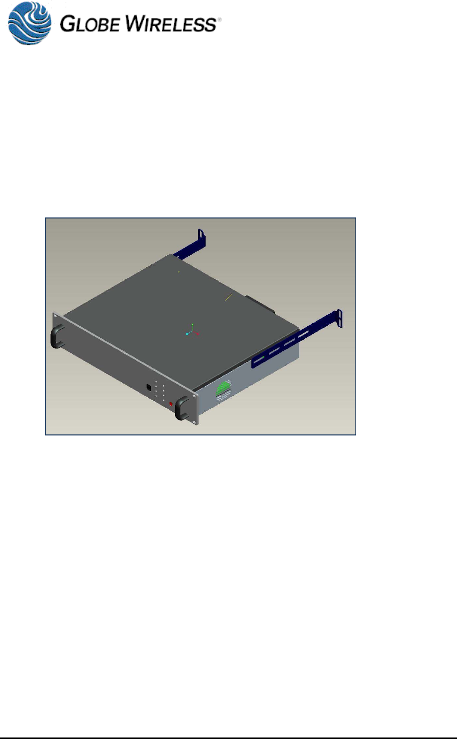
4.3.1 Installing the Globe i250 into 19” High Profile Rack Cabinet
The Globe i250 is designed to be inserted into a 19” Rack Cabinet. The 2U front panel has four
holes, used to secure the enclosure case into the cabinet by means of four M5x20mm screws.
Additionally, two handles are included on the front panel so that the case can be carried with ease.
Two long mounting brackets are mounted on each side of the enclosure case so that the end of
each bracket can be secured to the rear rails of the cabinet. Additional slots along the mounting
bracket are for the different depth cabinets.
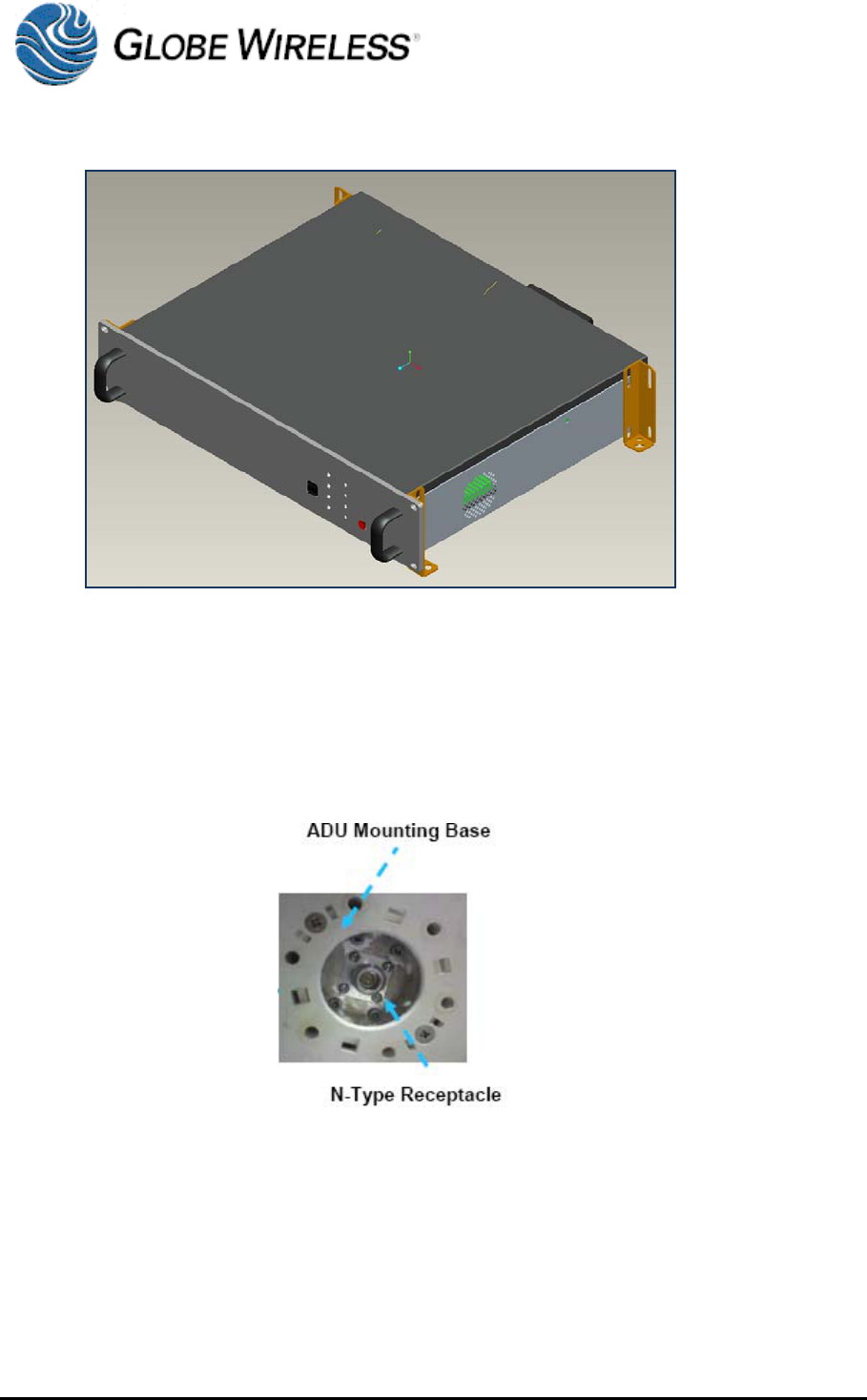
4.3.2 Installing the Globe i250 onto Wall, Shelf or Table
Four small mounting adaptors are attached at each corner of the enclosure case so they can be
mounted onto a wall, shelf or table with four M5x12mm self-tapping screws.
May 2010
IG266 Rev A
Globe Wireless Installation Guide – IG266 Rev A 4-4
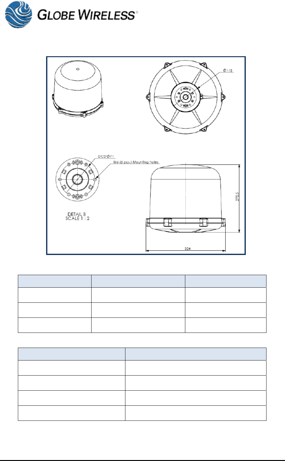
4.3.3 Installing the ADE
The antenna system is a FleetBroadband Class 9 system, based on 3 axes. Communication
between BDE and ADE is through a simple coaxial cable. There is an N-type coaxial connector at
the center of the ADE base. The antenna cable should be inserted here first before proceeding to
the installation of the ADE. The ADE contains a GPS antenna, RF unit, and circuit cards for
communication and antenna stabilization.
May 2010
IG266 Rev A
Globe Wireless Installation Guide – IG266 Rev A 4-5
The location of the ADE must be kept away from the beam width of any search/tracking radars.
Radar Power Operation Damage
0-10kW Distance=5m Distance=2m
10-30kW Distance=9m Distance=4m
30-50kW Distance=12m Distance=5m
The ADE line of sight shall not be obstructed by any large obstacles such as funnels or antennas.
Size (Diameter) Distance (Minimum)
16cm 3m
26cm 5m
52cm 10m
104cm 20m
The ADE must be installed as far away as possible from the ship’s radio antennas
For safety, all personnel should be kept at least 1 meter away from the ADE
May 2010
IG266 Rev A
Globe Wireless Installation Guide – IG266 Rev A 4-6
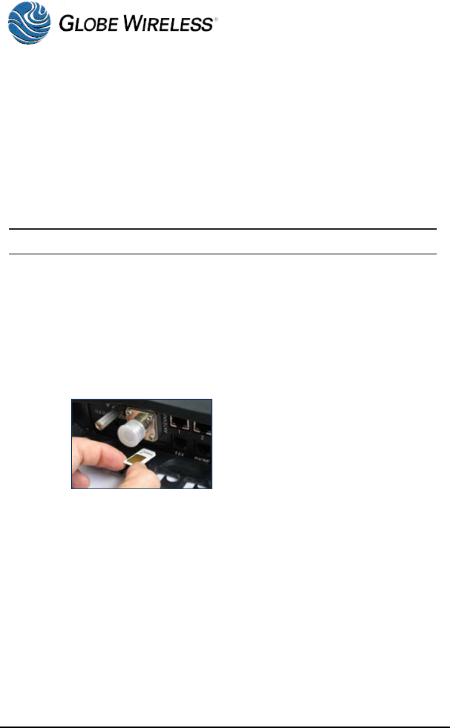
4.3.4 Installing the SIM Card
Prior to installing the SIM card, the following must be accomplished:
Connect the ADE to the BDE using the supplied coaxial cable
Connect the IP handset to the Primary handset Port
Connect the interface computer to LAN1 and ensure the computer IP configuration is set to
Configure Local Area Network (LAN) settings on the test PC to IP Address 192.168.1.34
with a subnet mask of 255.255.255.0 and the default gateway will be set to 192.168.1.35
CAUTION! Never insert or remove the SIM Card when the unit is powered on.
Perform the following steps to install the SIM card:
Step 1 Ensure the terminal is powered down.
Step 2 Remove the screw securing the SIM card protection cover.
Step 3 Remove the SIM card protection cover.
Step 4 Insert the SIM card into the cardholder.
Step 5 Install the SIM card protection cover.
May 2010
IG266 Rev A
Globe Wireless Installation Guide – IG266 Rev A 5-1
5.0 Setup Instructions
5.1 LAN setup for communication on Shipboard Network
If the terminal will be connected to a shipboard network and the IP Address and DHCP settings
must be changed, perform the following steps to configure the terminal:
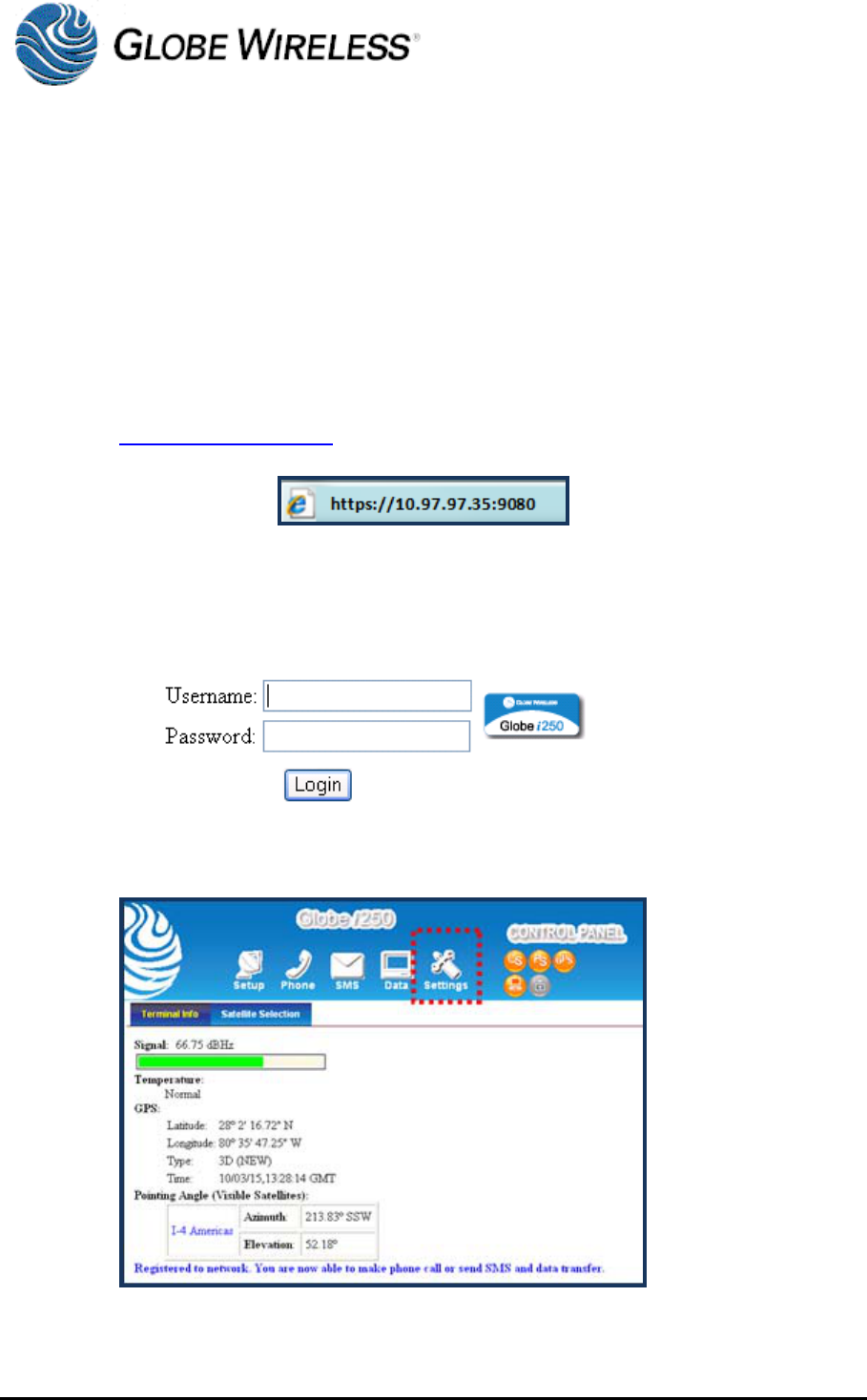
Step 1 On a computer connected to the terminal, open your web browser and type
https://10.97.97.35:9080 in the address field.
Step 2 Press Enter to display the login screen.
Step 3 Type in the Username and Password. Click the Login button.
Step 4 Click on the Settings button at the top of the web interface page.
May 2010
IG266 Rev A
Globe Wireless Installation Guide – IG266 Rev A 5-2
5.2 Satellite Search
Once all the connections have been made and the SIM card has been installed, power on the
terminal. The system will automatically detect the satellite position based on GPS data from the
antenna’s built-in GPS.
The LCD screen on the handset will display READY once the terminal is ready to communicate. In
some instances an APN must be entered in order for a satellite terminal to successfully make a
data connection. Use the following instructions to enter the APN information in this terminal:
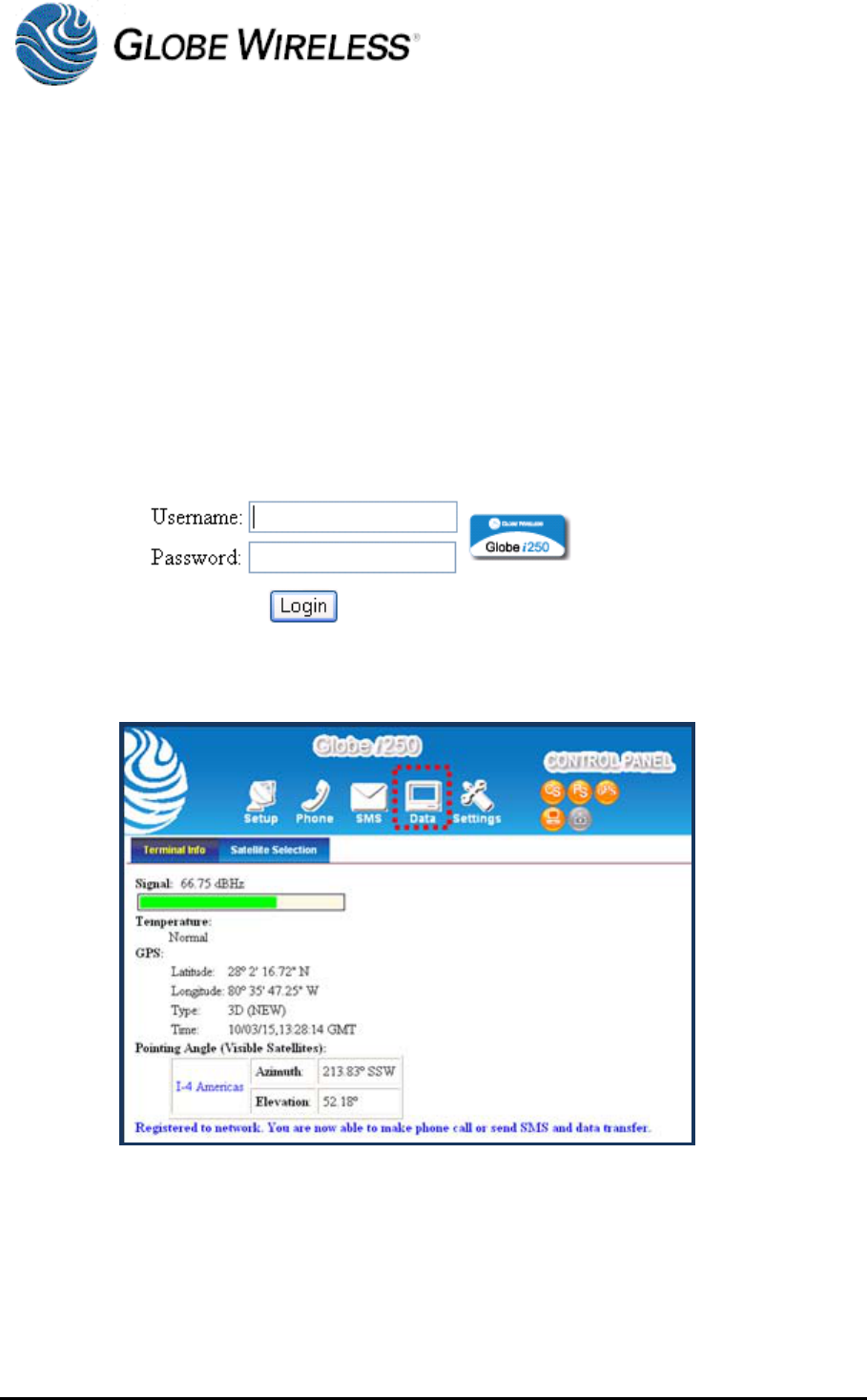
Step 1 Open a web browser and enter the Terminal IP Address in the address bar to access
the web interface. Enter Username and Password.
Step 2 Click on the Data button and then the Primary Connections tab.
Step 3 Enter the specific APN configuration as well as the Login and Password information
if applicable.
May 2010
IG266 Rev A
Globe Wireless Installation Guide – IG266 Rev A 5-3
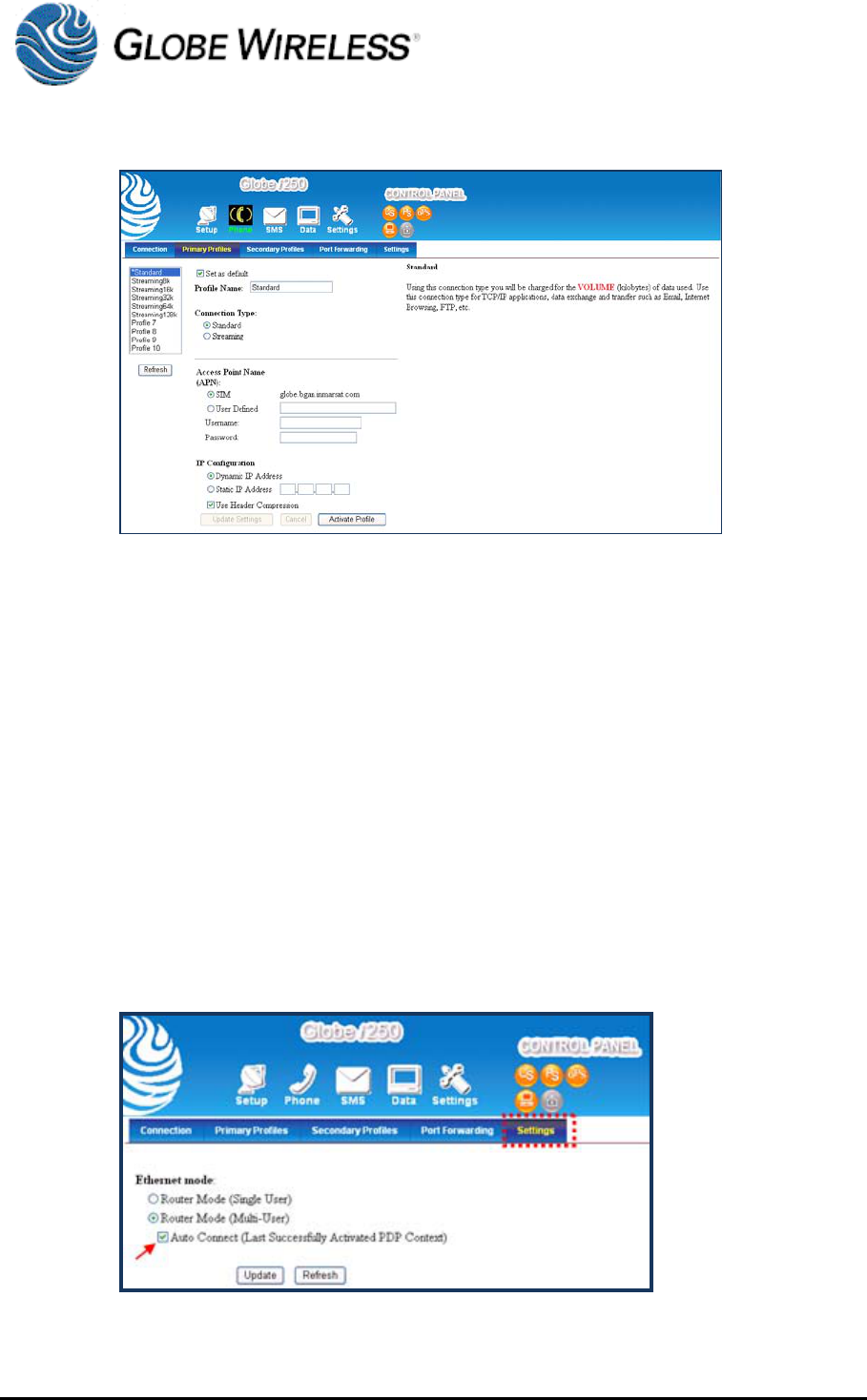
Step 4 Click the Update Settings button located at the bottom of the page for the settings to
be implemented.
5.3 Initiating a Data Connection
To utilize the data packet features, a data connection must be initiated through the Web Interface
or the IP handset.
Step 1 Open the Web Interface at address http://192.168.1.35 and enter the login and
password. Once logged into the web interface, click the Data button located at the
top of the web interface page and then click the Primary tab. Enter appropriate
information as needed and at the bottom of the page click the Activate Profile
button.
Step 2 After updating the profile click on the Settings tab and select the Auto Connect
option to ensure the terminal will reconnect to the BGAN network in the event of
service interruption.
May 2010
IG266 Rev A
Globe Wireless Installation Guide – IG266 Rev A 5-4
5.4 Making Voice Calls
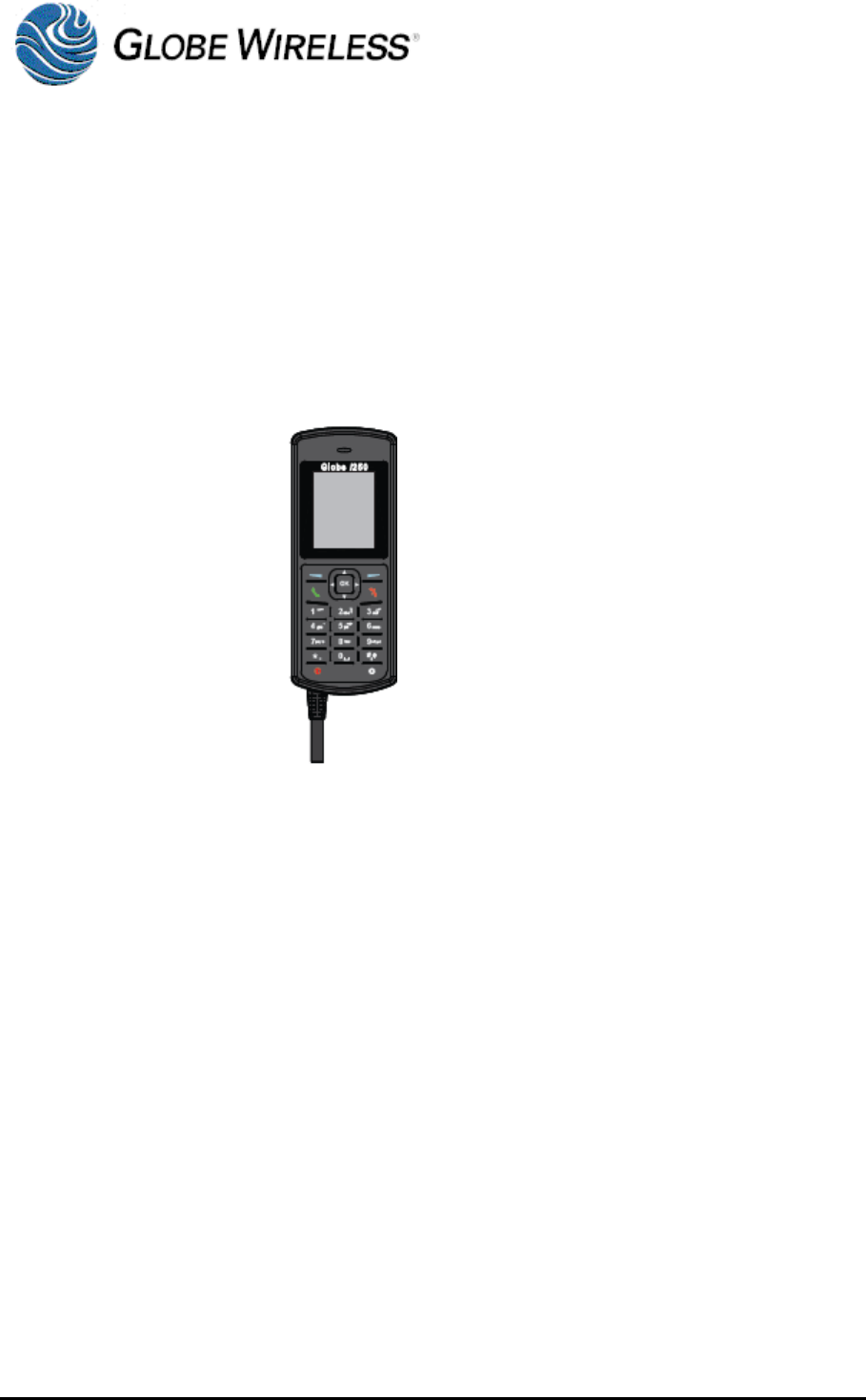
5.4.1 Voice Connections using the Handset
It is not necessary for a data connection to be present in order to make voice calls. When making
voice calls from the handset, perform the following:
Step 1 Verify there is good signal strength and the handset displays READY.
Step 2 Remove the handset from the hook and dial the desired phone number followed by
the # sign in the following format:
00+Country Code+Area Code+Subscriber’s Number+#
Example: 0013213080112#