InnerWireless IWAPINTERFACEG Access Point System User Manual Installation Guidelines
InnerWireless, Inc. Access Point System Installation Guidelines
Contents
- 1. OEM Installation Instruction
- 2. User Manual
- 3. Users Manual
Users Manual

InnerWireless, Inc.
Richardson, Texas
InnerWireless Access Point Interface
COPYRIGHT© 2003 InnerWireless
ALL RIGHTS RESERVED
All information set forth in this document and all rights in and to intellectual property
disclosed herein are the exclusive property of InnerWireless. No disclosure of this
document and/or the information contained herein shall be made to any other person
or organization without the prior written consent of InnerWireless.
Table of Contents
Table of Contents........................................................................................................- 2 -
1 FRONT CHAPTER...............................................................................................- 3 -
1.1 POLICY FOR INNERMOBILE® SYSTEM WARRANTY AND SUPPORT
SERVICES ..............................................................................................................- 3 -
1.2 TO RETURN EQUIPMENT FOR REPAIR:...................................................- 4 -
1.3 CONVENTIONS............................................................................................- 4 -
1.4 RF EXPOSURE COMPLIANCE....................................................................- 4 -
1.5 PRECAUTIONS ............................................................................................- 5 -
2 PURPOSE AND SCOPE .....................................................................................- 5 -
3 802.11 ACCESS POINT CONNECTION TO WDS SYSTEM ..............................- 6 -
- 2 -
1 FRONT CHAPTER
1.1 POLICY for InnerMobile® System Warranty and Support Services
1.1.1 INNERMOBILE® SYSTEM STANDARD WARRANTY
InnerWireless, Inc. warrants, for a period of one (1) year beginning upon the sign off of the
InnerWireless Acceptance Test Procedure (ATP) for the identified InnerMobile® System
provided herein, to be free from defects in materials and workmanship, and will operate and
conform according to the product specifications. Warranty provided does not assure
uninterrupted operation of the equipment, nor does it include any repairs necessitated by
Customer’s, or third party’s, improper or unauthorized use or modification of the System.
Customer accepts all responsibility for the physical security of the System.
Warranty includes all parts and materials, with exceptions (see below), to meet the engineered
specification contained in the contract. Customer will approve the engineered specifications per
the InnerWireless acceptance and signoff procedure.
InnerMobile® Equipment included in warranty:
In the event that service is disabled or degraded from it’s original design, InnerWireless
warrants all original equipment installed as part of the InnerMobile® System. The original
equipment as it relates to the specific installation may include the following.
• Coax cable required to deliver the RF signal through out each floor of the building
• Jumper cables and connectors required to assemble the InnerMobile® System
• Access Point Interface (API) utilized as part of the InnerMobile® System
• Any antenna required to radiate the RF signal to the intended areas
InnerWireless, Inc., at its sole discretion, will repair or replace any components of the
InnerMobile® System that are found to be faulty. Any replacements will be shipped from
InnerWireless Inc. via next day delivery from the time the parts are available. InnerWireless will
not maintain, or allow for the storage of spare components at the customer site.
All warranty work shall be performed after notification by Customer that the system, or portion of
the system, is inoperative, and Customer has followed the published procedures to troubleshoot
and repair the failure without success.
This warranty is expressly in lieu of any other warranties, express or implied, including any
implied warranty of merchantability or warranty of fitness for a particular purpose, and of any
other obligation or liability on the part of InnerWireless: InnerWireless neither assumes nor
authorizes any other person to assume for it any liability in connection with its products. In no
event shall InnerWireless be liable for any indirect, incidental, special or consequential damages
arising out of the sale, manufacture or use of any of its products. In any event, the total liability
of InnerWireless arising from any cause of action or claim whatsoever, whether (1) in contract,
(2) in tort (including negligence, whether sole, joint, contributory, concurrent or otherwise), (3)
under strict liability, (4) under any environmental or antipollution law or regulation, (5) connected
with any toxic or hazardous substance or constituent, (6) arising out of any representation or
instruction, or under any warranty, (7) or otherwise, arising out of, connected with, or resulting
from the design, manufacture, sale, resale, delivery, repair, replacement or use of products or
the furnishing of any service shall in no event exceed the price allocable to and paid to
- 3 -

InnerWireless for the individual unit of products or service or part thereof which gives rise to the
cause of action or claim.
1.2 TO RETURN EQUIPMENT FOR REPAIR:
• Be able to communicate to InnerWireless the nature of the problem with the equipment
• Provide to InnerWireless your specific company name, ship to address, contact name
and phone number.
• Call the customer service center to set up appropriate return address, per the
component being returned for repair.
• InnerWireless return address:
InnerWireless, Inc. Repair Services
1155 Kas Drive, Suite 200
Richardson, TX, 75081
1-866-472-9898
1.3 CONVENTIONS
In this manual the following special formats are used:
! Warning
WARNINGS CONTAIN INFORMATION REGARDING DANGEROUS FUNCTIONS.
1.4 RF EXPOSURE COMPLIANCE
! Warning
TO COMPLY WITH FCC RF EXPOSURE COMPLIANCE REQUIREMENTS, ANTENNAS
USED FOR THIS PRODUCT MUST BE FIXED MOUNTED ON INDOOR PERMANENT
STRUCTURES, PROVIDING A SEPARATION DISTANCE OF AT LEAST 20 CM FROM ALL
PERSONS DURING NORMAL OPERATION.
- 4 -

1.5 PRECAUTIONS
PERSONAL AND EQUIPMENT SAFETY
• Changes or modifications to this device not expressly approved by the manufacturer could void
the user’s authority to operate the equipment.
• Refer to the User’s Manual supplied by Cisco Systems, Inc. for information on the Access Point
usage and installation.
• Disconnect both power sources before servicing any equipment.
! Warning
THE USE OF CONTROLS OR ADJUSTMENTS OR PERFORMANCE PROCEDURES OTHER
THAN THOSE SPECIFIED HEREIN MAY RESULT IN HAZARDOUS RADIATION EXPOSURE.
2 PURPOSE AND SCOPE
This manual provides InnerWireless’ certified installers with guidelines for successful
deployment of the InnerWireless Access Point Interface.
- 5 -
3 802.11 ACCESS POINT CONNECTION TO WDS SYSTEM
802.11 access points (AP) will be interconnected to the InnerWireless WDS system via a
custom Access Point Interface.
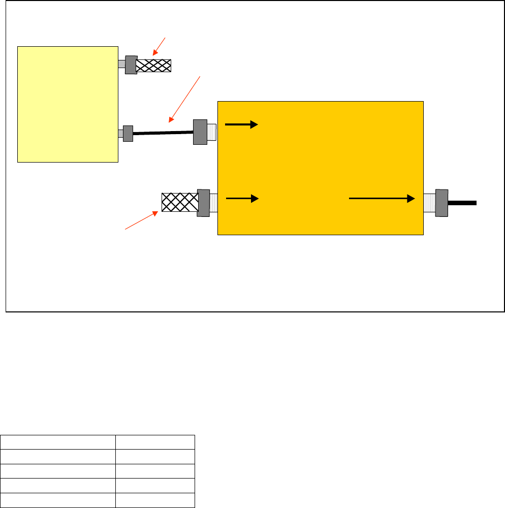
The installation requires no special tools or installation techniques. The most important item to
remember is interconnecting the access point via the correct port of the Access Point Interface
(labeled 2.4GHz port). Figure 1 depicts an interconnection diagram. Also note that a Reverse
Polarity TNC to N-Male jumper cable is used to interconnect the access point to the Access
Point Interface.
50 OHM
TERMINATION
REVERSE POLARITY TNC
802.11 MALE TO N MALE JUMPER
ACCESS
POINT Access Point Interface
-
2400 – 2485 MHz
400 – 2170 MHz OUT
To
50 OHM
TERMINATION Antenna
Network
Figure 1 - 802.11 Access Point to Interconnection to WDS
The InnerMobile® System supports 4 types of antenna elements;
• Log Periodic Antenna
• Thin (PCB) Log Periodic Antenna
• Discone Antenna
• ½” Radiating cable
Antenna Type Gain (dBi)
LPA 7.1
PCB LPA 7.1
Discone 5.8
½” Radiating cable <0.0
- 6 -
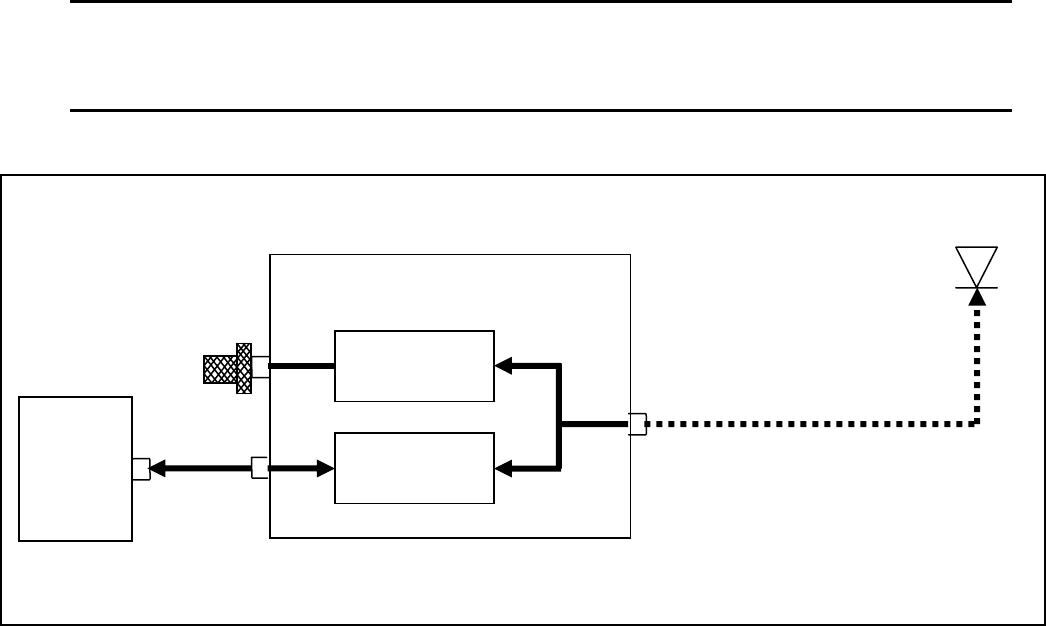
The 3 basic network configurations are;
! Warning
TO COMPLY WITH FCC RF EXPOSURE COMPLIANCE REQUIREMENTS, ANTENNAS
USED FOR THIS PRODUCT MUST BE FIXED MOUNTED ON INDOOR PERMANENT
STRUCTURES, PROVIDING A SEPARATION DISTANCE OF AT LEAST 20 CM FROM ALL
PERSONS DURING NORMAL OPERATION.
Cisco
1200
Access
Point
le
Discone
RP-TNC
to N cab
½” Radiating cable, 10 ft.
Bandpass filter
2400 – 2485MHz
Bandpass filter
400 – 2170MHz
Access Point Interface
50 Ohm Term.
Basic configuration with ½” Radiating cable and Discone antenna
- 7 -
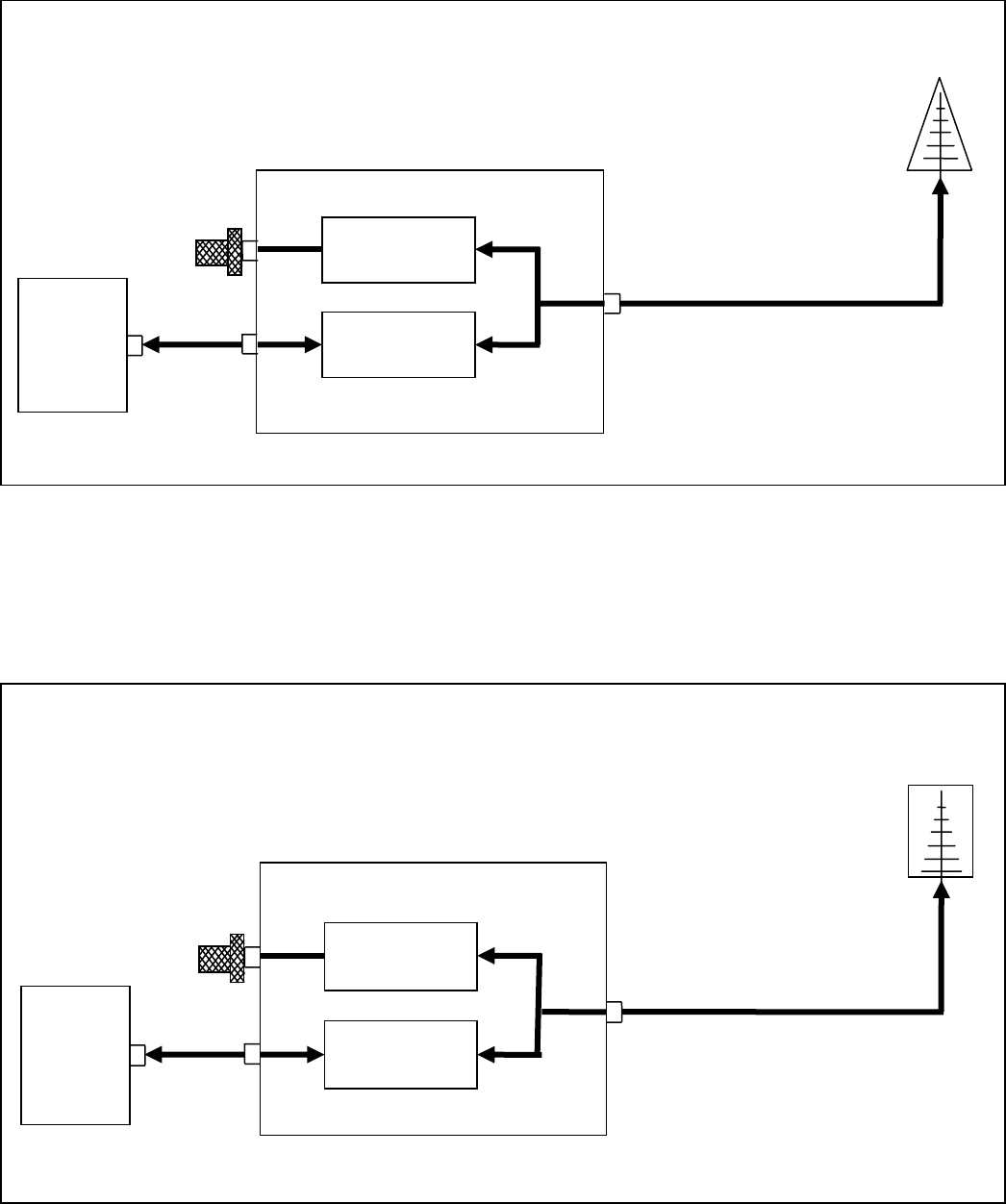
Cisco
1200
Access
Point
Access Point Interface
Bandpass filter
400 – 2170MHz
Bandpass filter
2400 – 2485MHz
50 Ohm Term.
le
RP-TNC
to N cab
4 meter
j
um
p
er cable
LPA
Basic configuration with a 4 meter jumper cable and LPA antenna
Cisco
1200
Access
Point
Access Point Interface
Bandpass filter
400 – 2170MHz
Bandpass filter
2400 – 2485MHz
50 Ohm Term.
4 meter
j
um
p
er cable
le
RP-TNC
to N cab
PCB LPA
Basic configuration with 4 meter jumper cable and PCB LPA antenna
- 8 -