InnoComm Mobile Technology SN10-22 SigFox module User Manual
InnoComm Mobile Technology Corporation SigFox module
UserManual.wiki
>
InnoComm Mobile Technology
>
SN10 22 User Manual
User Manual
Navigation menu
Upload a User Manual
Namespaces
Wiki Guide
HTML
PDF
Info
Views
User Manual
Discussion / Help
Navigation


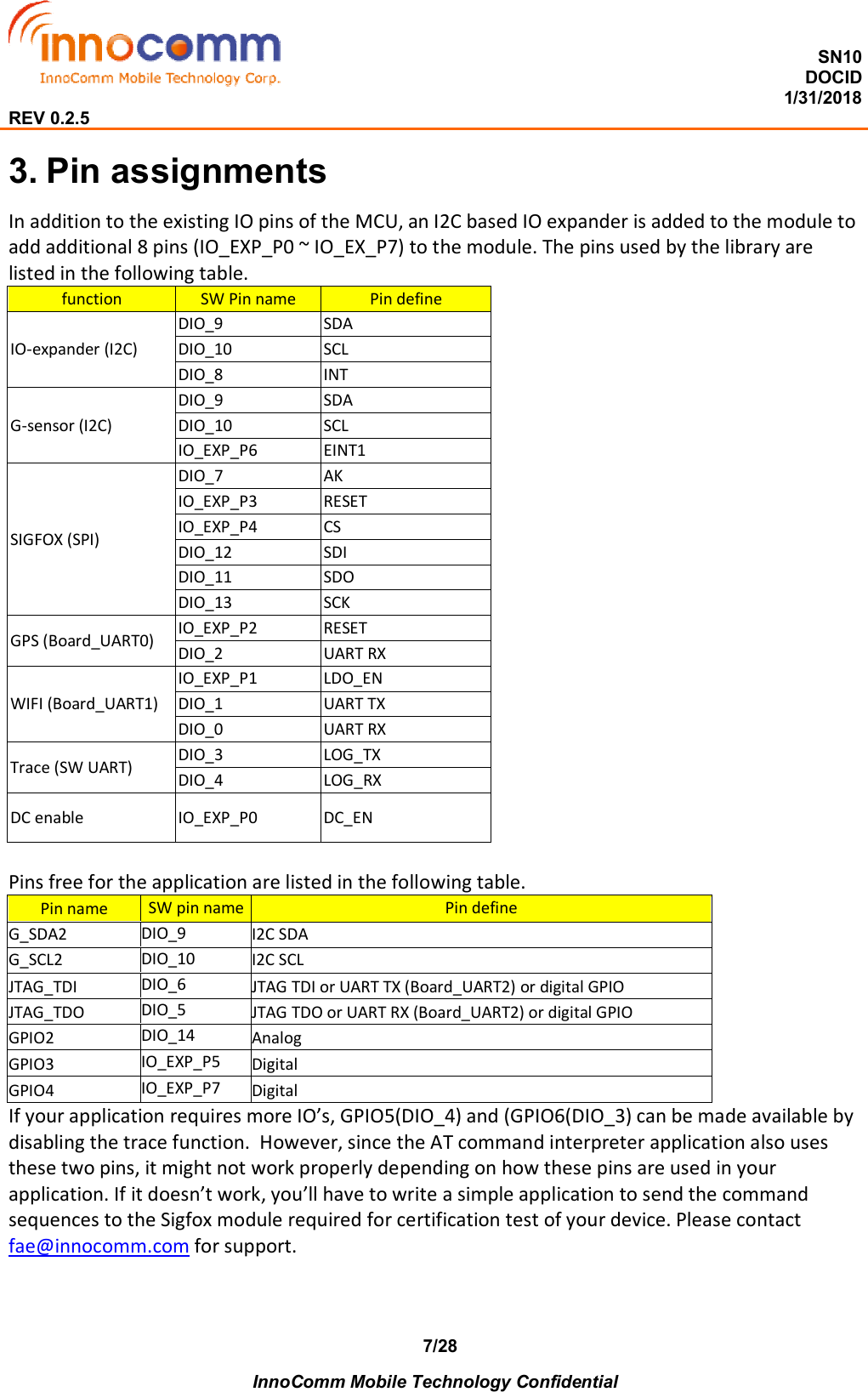

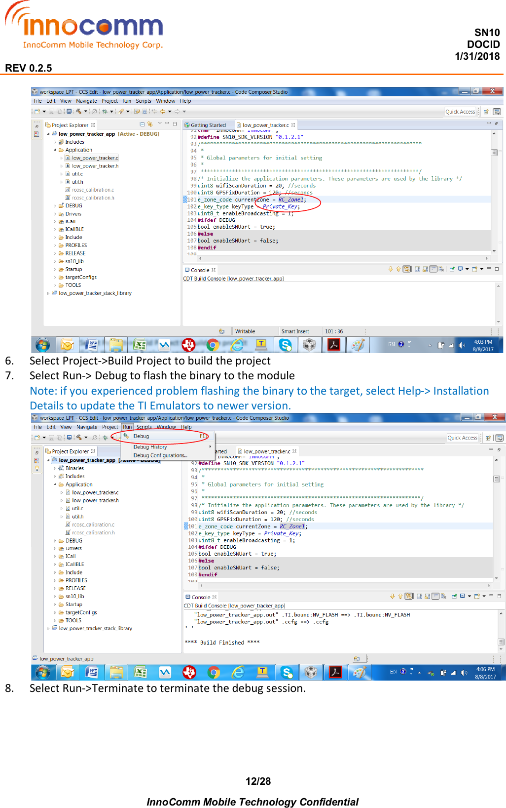
![SN10 DOCID 1/31/2018 REV 0.2.5 InnoComm Mobile Technology Confidential 15/28 FX_TEST_MODE_RX_PROTOCOL = 2, FX_TEST_MODE_RX_GFSK = 3, SFX_TEST_MODE_RX_SENSI = 4, SFX_TEST_MODE_TX_SYNTH = 5, } sfx_test_mode_t; Used in sendTestMode() function to select the test mode. typedef struct { uint8 devId[BSSID_LEN]; int16 rssi; } wifiAPRec_t; Used in scanWifiAPs() function to hold the information of the returned Wifi APs. typedef struct { float latitude; float longitude; } gpsRec_t; Used in fixGPSLocation() function to hold the latitude and longitude of the fix. typedef union { int8 s; uint8 us; int16 i; uint16 ui; int32 l; uint32 ul; float f; char *p; } data_t; Used in trace() function to indicate the type of data to be print out.](https://usermanual.wiki/InnoComm-Mobile-Technology/SN10-22/User-Guide-3770001-Page-15.png)
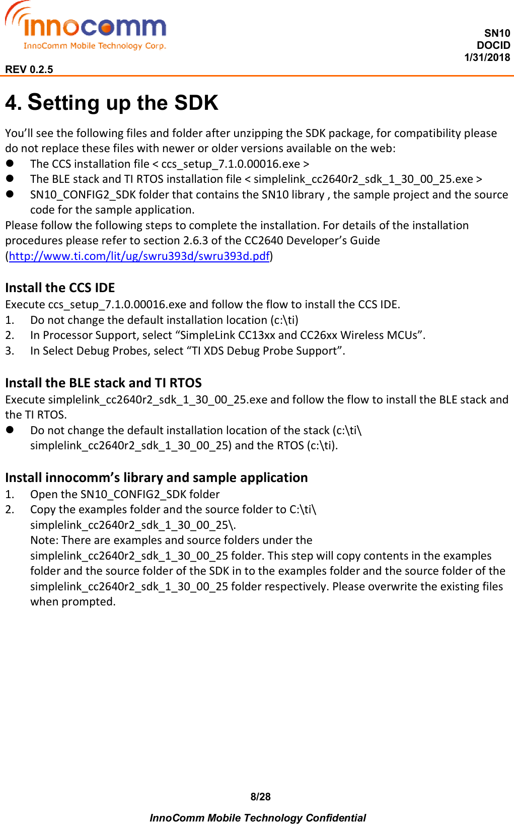
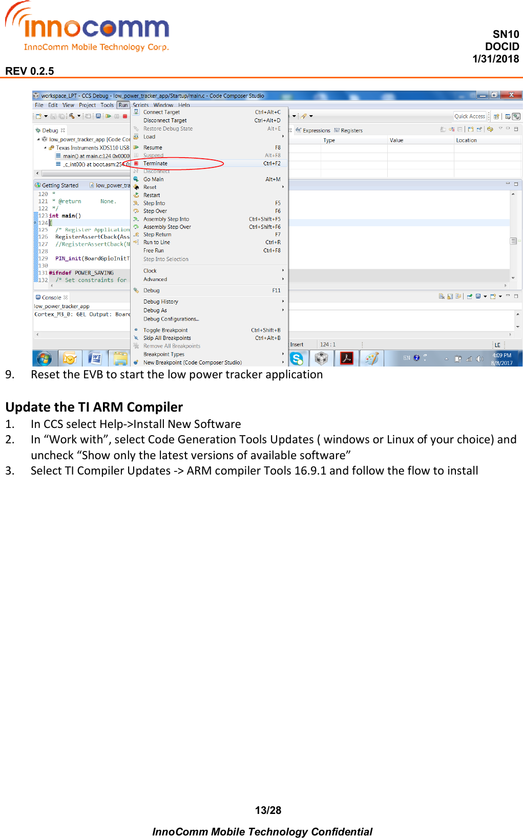
![SN10 DOCID 1/31/2018 REV 0.2.5 InnoComm Mobile Technology Confidential 16/28 6. Functions 6.1 Module void initiateModule(void (*IOexpanderCB)(), void (*GAPEvtCB)()) Function to initiate the module. Parameters: [in] void (*IOexpanderCB)() Pointer to the call back function for the IOexpander interrupts [in] void(*GAPEvtCB)() Pointer to the call back function for the GAP events Return: None 6.2 SIGFOX e_sfx_ret sendData(uint8 *payload, uint8 payloadLen, uint8 *rcvBuf, uint8 *pLen) Function to send data to the SIGFOX network. This function will wake up the SIGFOX module, switch to the designated RCZ, send the payload and at the end, send the SIGFOX module to sleep. Parameters: [in] payload The payload to be sent to the network. [in] payloadLen, up to 12. Size of the payload in bytes. [out] rcvBuf The feedback from the network. Should pass NULL if not expecting feedback. [out] pLen Size of the feedback in bytes. Return: SIGFOX_OK or SIGFOX_NOK e_sfx_ret sendBitStatus(uint8 bitValue, uint8 *rcvBuf, uint8 *pLen) Function to send bit status to the SIGFOX network. This function will wake up the SIGFOX module, switch to the designated RCZ, send the bit status and at the end, send the SIGFOX module to sleep. Parameters: [in] bitValue The status, should be 0 or 1. [out] rcvBuf The feedback from the network. Should pass NULL if not expecting feedback. [out] pLen Size of the feedback in bytes Return:](https://usermanual.wiki/InnoComm-Mobile-Technology/SN10-22/User-Guide-3770001-Page-16.png)
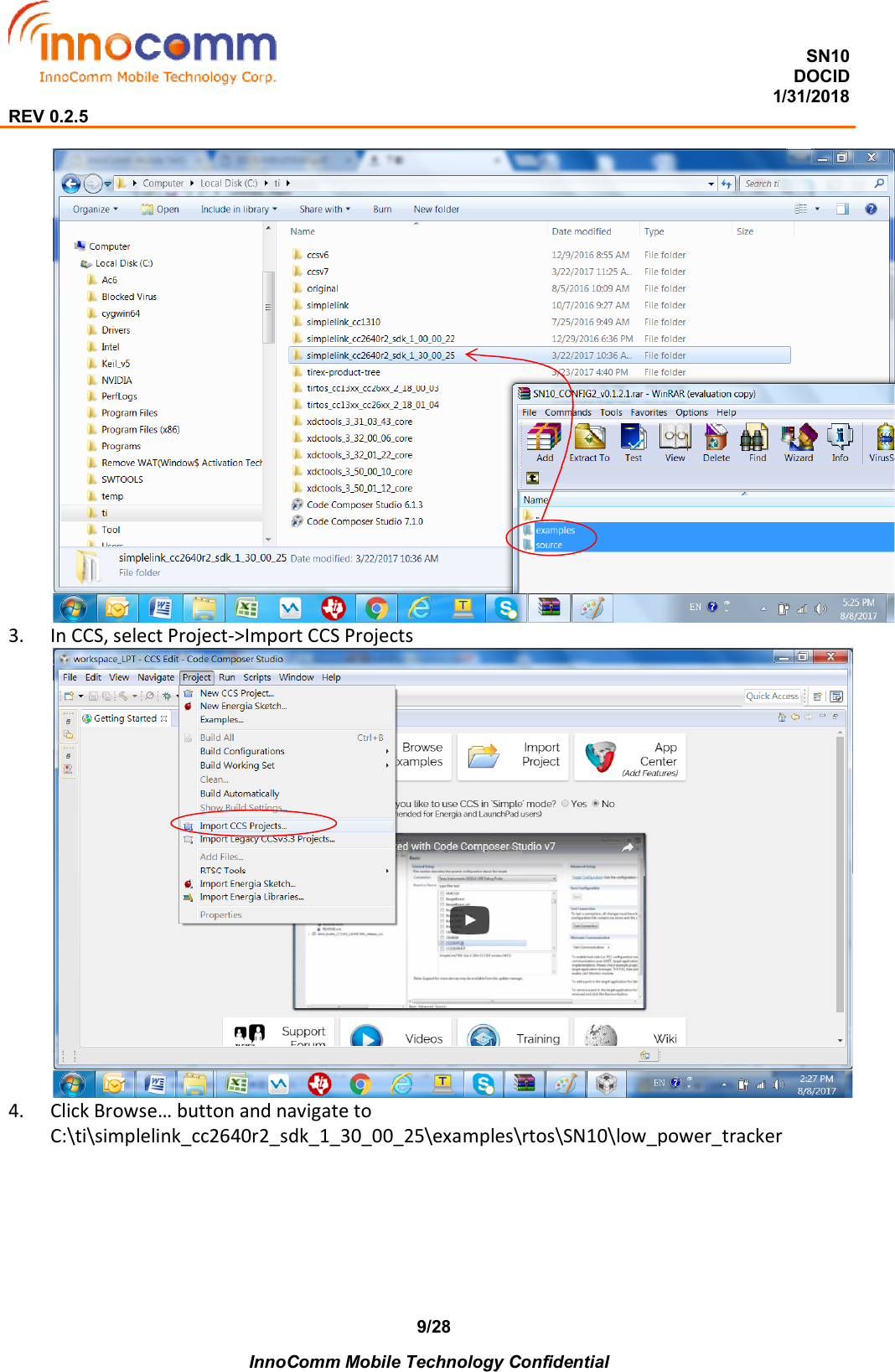
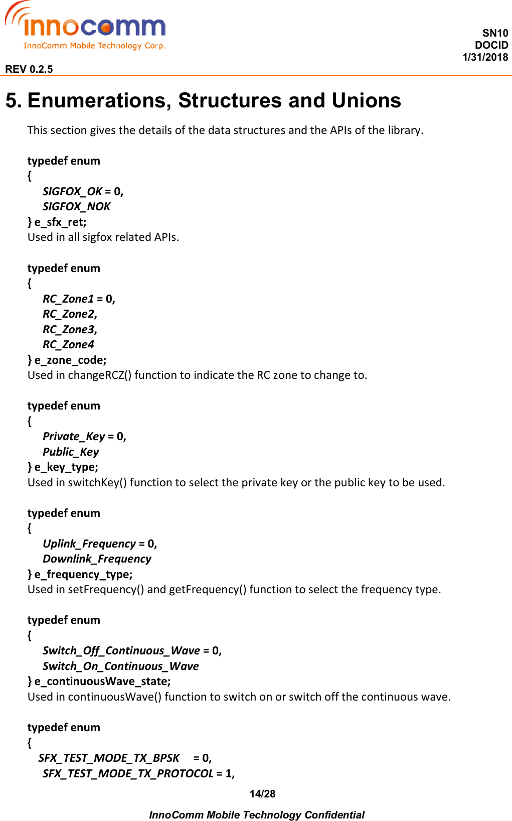
![SN10 DOCID 1/31/2018 REV 0.2.5 InnoComm Mobile Technology Confidential 17/28 SIGFOX_OK or SIGFOX_NOK (The aforementioned two APIs should be sufficient for most of the applications. The following APIs are only needed only if finer control of the SIGFOX module is required) e_sfx_ret sendWakeup() Function to wakeup the SIGFOX module. Parameters: None Return: SIGFOX_OK or SIGFOX_NOK e_sfx_ret sendToSleep() Function to send the SIGFOX module to sleep. Parameters: None Return: SIGFOX_OK or SIGFOX_NOK. e_sfx_ret sendPayload(uint8 *payload, uint8 payloadLen, uint8 *rcvBuf, uint8 *pLen) Function to send payload to the network and optionally receive feedback from it. Parameters: [in] payload The payload to be sent to the network. [in] payloadLen, up to 12. Size of the payload in bytes. [out] rcvBuf The feedback from the network. Should pass NULL if not expecting feedback. [out] pLen Size of the feedback in bytes. Return: SIGFOX_OK or SIGFOX_NOK. e_sfx_ret sendBit(uint8 bitValue, uint8 *rcvBuf, uint8 *pLen) Function to send a bit status to the network and optionally receive feedback from it. Parameters: [in] bitValue The status, should be 0 or 1. [out] rcvBuf The feedback from the network. Should pass NULL if not expecting feedback. [out] pLen Size of the feedback in bytes Return: SIGFOX_OK or SIGFOX_NOK.](https://usermanual.wiki/InnoComm-Mobile-Technology/SN10-22/User-Guide-3770001-Page-17.png)
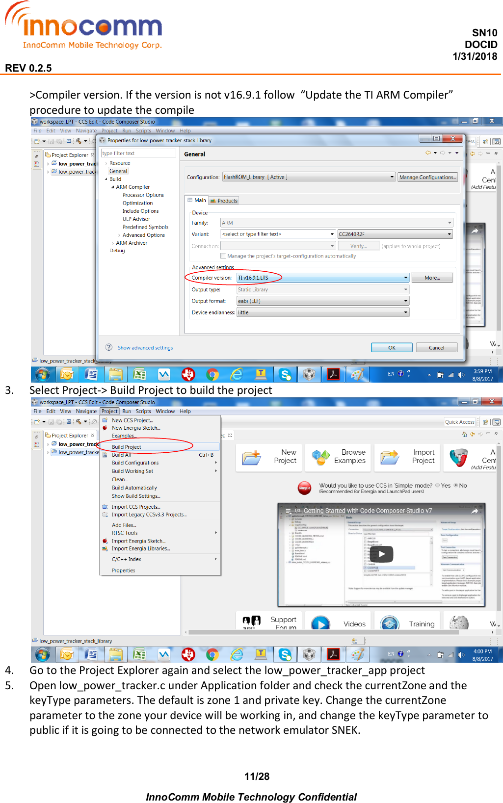
![SN10 DOCID 1/31/2018 REV 0.2.5 InnoComm Mobile Technology Confidential 18/28 e_sfx_ret sendOutOfBand() Function to have SIGFOX module send out of band message. Parameters: None. Return: SIGFOX_OK or SIGFOX_NOK. e_sfx_ret getInfo(uint8 *deviceId, uint8 *pac, char *libVersion) Function to get the information of the SIGFOX module. Parameters: [out] deviceId The 4 bytes SIGFOX ID of the SIGFOX module [out] pac The 8 bytes PAC of the SIGFOX module [out] libVersion The library version, 11 bytes. Return: SIGFOX_OK or SIGFOX_NOK. e_sfx_ret setFrequency (e_frequecny_type fType, uint32 freq) Function to set the frequency of the SIGFOX module Parameters: [in] fType Uplink_Frequency or Downlink_Frequency. [in] freq The frequency to set to. Return: SIGFOX_OK or SIGFOX_NOK. e_sfx_ret getFrequency (e_frequecny_type fType, uint32* freq) Function to get the frequency of the SIGFOX module Parameters: [in] fType Uplink_Frequency or DownLInk_Frequency [in] freq The returned frequency. Return: SIGFOX_OK or SIGFOX_NOK. e_sfx_ret continuousWave (e_continuousWave_state state) Function to have the SIGFOX module send continuous wave Parameters: [in] state Switch_On_Continuous_Wave or Switch_Off_Continuous_Wave [in] freq](https://usermanual.wiki/InnoComm-Mobile-Technology/SN10-22/User-Guide-3770001-Page-18.png)
![SN10 DOCID 1/31/2018 REV 0.2.5 InnoComm Mobile Technology Confidential 19/28 The returned frequency. Return: SIGFOX_OK or SIGFOX_NOK. e_sfx_ret getDeviceVersion (char *hwVersion, char *devVersion) Function to get the hardware version and the device version of the SIGFOX module Parameters: [out] hwVersion 8 bytes hardware version [out] devVersion 7 bytes device version. Return: SIGFOX_OK or SIGFOX_NOK. e_sfx_ret triggerWatchdog () Function to reset the SIGFOX module Parameters: None Return: SIGFOX_OK or SIGFOX_NOK e_sfx_ret sendTestMode(sfx_test_mode_t txTestMode, uint8 txTestConfig) Function to have the SIGFOX module send signals for RF testing. Parameters: [in] txTestMode [in] txTestConfig Return: SIGFOX_OK or SIGFOX_NOK. e_sfx_ret changeRCZ (e_zone_code zone) Function to switch to the selected zone. Parameters: [in] zone RC_Zone1, ETSI Europe (863~870MHz) RC_Zone2, FCC US (902~928MHz) RC_Zone3, ARIB Japan, Korea (915~930MHz) RC_Zone4, FCC Latin America, Australia, New Zealand (902~915MHz) Return: SIGFOX_OK or SIGFOX_NOK. e_sfx_ret switchKey (e_key_type keyType) Function to switch to selected key type. Parameters: [in] keyType Public_Key, use public key](https://usermanual.wiki/InnoComm-Mobile-Technology/SN10-22/User-Guide-3770001-Page-19.png)
![SN10 DOCID 1/31/2018 REV 0.2.5 InnoComm Mobile Technology Confidential 20/28 Private_Key, use private key Return: SIGFOX_OK or SIGFOX_NOK. e_sfx_ret setFCCMacroChannel(char *configString, uint8 defaultChannel) Function to configure the enabled channels for FCC Parameters: [in] configString Configuration (disabled or enabled) of the Macro channels. [in] defaultChannel The default SIGFOX macro channel. Return: SIGFOX_OK or SIGFOX_NOK. void toZone(e_zone_code zone) Function to set the zone code of the module. Parameters: [in] zone Zone to set to Return: None void useKeyType (e_key_type type) Function to set the module to use private key or public key when sending data to the network. Parameters: [in] type Private key or public key Return: None uint8 getErrCode() Function to the error code of a sigfox API. Parameters: None Return: uint8 errCode 6.3 WIFI & GPS uint8 scanWifiAPs(wifiAPRec_t *APList) Function to scan the surrounding for the top two Wifi APs of strongest signal. Parameters: [out] APList Records of the Wifi APs found.](https://usermanual.wiki/InnoComm-Mobile-Technology/SN10-22/User-Guide-3770001-Page-20.png)
![SN10 DOCID 1/31/2018 REV 0.2.5 InnoComm Mobile Technology Confidential 21/28 Return: Number of the APs found: 0, 1, or 2. bool fixGPSLocation (gpsRec_t *GPSInfo) Function to get the fix of the GPS location. Parameters: [out] GPSInfo Latitude and longitude of the fix. Return: true if a fix is attained, false otherwise. 6.4 Bluetooth void BLEBroadcaster_processStackMsg(ICall_Hdr *pMsg) Function to process the BLE stack message. Parameters: [in] pMsg Return: None. void BLEBroadcaster_processStateChangeEvt(gaprole_States_t newState) Function to process the state change events from GAP. Parameters: [in] newState Return: None. void setBroadcastInterval(uint16 interval) Function to set the interval of the beacon broadcast. Parameters: [in] interval Time interval in ms. Return: None. void setBroadcastData(uint8* data) Function to set the beacon broadcast data. Parameters: [in] data Broadcast data. Return: None. void getBroadcastData(uint8* data)](https://usermanual.wiki/InnoComm-Mobile-Technology/SN10-22/User-Guide-3770001-Page-21.png)
![SN10 DOCID 1/31/2018 REV 0.2.5 InnoComm Mobile Technology Confidential 22/28 Function to get the beacon broadcast data. Parameters: [out] data Broadcast data. Return: None. void enableBroadcast() Function to enable beacon broadcast Parameters: None Return: None. void disableBroadcast() Function to disable beacon broadcast Parameters: None Return: None. 6.5 G-Sensor void setGsensor_Slope_Threshold(Slope_Threshold_Level Slope_Level) Function to set the G sensor slope threshold. Parameters: [in] Slope_Threshold_Level Slope_Level G sensor slope level. Return: None void setGsensor_HighG_Threshold(HigG_Threshold_Level HighG_Level) Function to set the G sensor slope threshold. Parameters: [in] HighG_Threshold_Level HighG_Level G sensor high G level. Return: None 6.6 Utilities void trace (char *str, data_t d) Function to print a trace line. Parameters:](https://usermanual.wiki/InnoComm-Mobile-Technology/SN10-22/User-Guide-3770001-Page-22.png)
![SN10 DOCID 1/31/2018 REV 0.2.5 InnoComm Mobile Technology Confidential 23/28 [in] str The format string. %ds for int8, %d for int16, %u for uint16, %l for int32, %ul for uint32, %s for char* [in] d Data to be print out Return: None. (Note: this function only takes one parameter, as follows: Int16 rssi = -109; trace (“RSSI = %d\r\n”, (data_t)rssi); ) 6.7 IO expander Void IOEXP_setPinConfig(uint8 pin, bool enable_int) Function to configure input pin. Parameters: [in] pin Pin ID, can be either IO_EXP_P4, IO_EXP_P5 or IO_EXP_P7 [in] enable_int, true or false. Uint8 IOEXP_getInputValue(uint8 pin) Function to get the input value of the input pin. Parameters: [in] pin Pin ID, can be either IO_EXP_P4, IO_EXP_P5 or IO_EXP_P7 Return: 0 or 1. void IOEXP_setOutputValue(uint8 pin, unit8 value) Function to set the value of the output pin. Parameters: [in] pin Pin ID, can be either IO_EXP_P4, IO_EXP_P5 or IO_EXP_P7 [in] value, 0 or 1](https://usermanual.wiki/InnoComm-Mobile-Technology/SN10-22/User-Guide-3770001-Page-23.png)