Innovation First VEXCAM-TX2 Color Camera User Manual
Innovation First, Inc. Color Camera
User Manual

Auxiliary Accessories
Inventor’s Guide insert Color Camera Kit • 1
accessories
Auxiliary
Color Camera Kit
For More Information, and additional Parts & Pieces refer to:
www.VEXRobotics.com
The Color Camera Kit can give you a new perspective. Use this wireless color camera to see
through your robot’s eyes. Connect the Camera Receiver to any television to see and hear from
your robot’s point-of-view via the camera link.
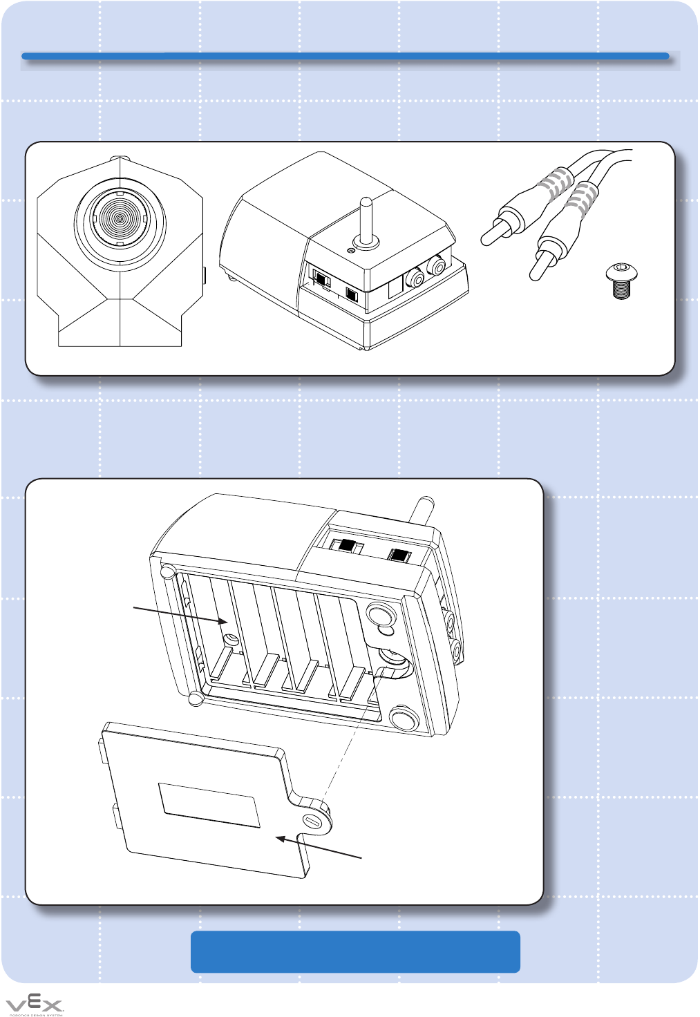
The rst step is to insert the batteries into the Camera Receiver. Using a Phillips head screw
driver, remove the screw and open the battery door on the bottom of the Camera Receiver.
Install (4x) AA-batteries, not included. Insert the batteries in the correct orientation by
following the polarity diagram inside the battery compartment. Reinstall battery door and screw.
(1x) Camera Unit
Battery
Compartment
Compartment
Door
(1x) Camera Receiver
(1x) RCA Cable
(2x) 8-32 X 1/4”
Mounting Screws
Limited 90-day Warranty
This product is warranted by
VEX Robotics, Inc. against
manufacturing defects in
material and workmanship
under normal use for ninety
(90) days from the date of
purchase from authorized
VEX Robotics dealers. For
complete warranty details
and exclusions, check with
your dealer.
VEX Robotics, Inc.
1519 IH 30 W
Greenville, TX 75402
1111

Auxiliary Accessories
Inventor’s Guide insertColor Camera Kit • 2
accessories
Color Camera Kit, continued
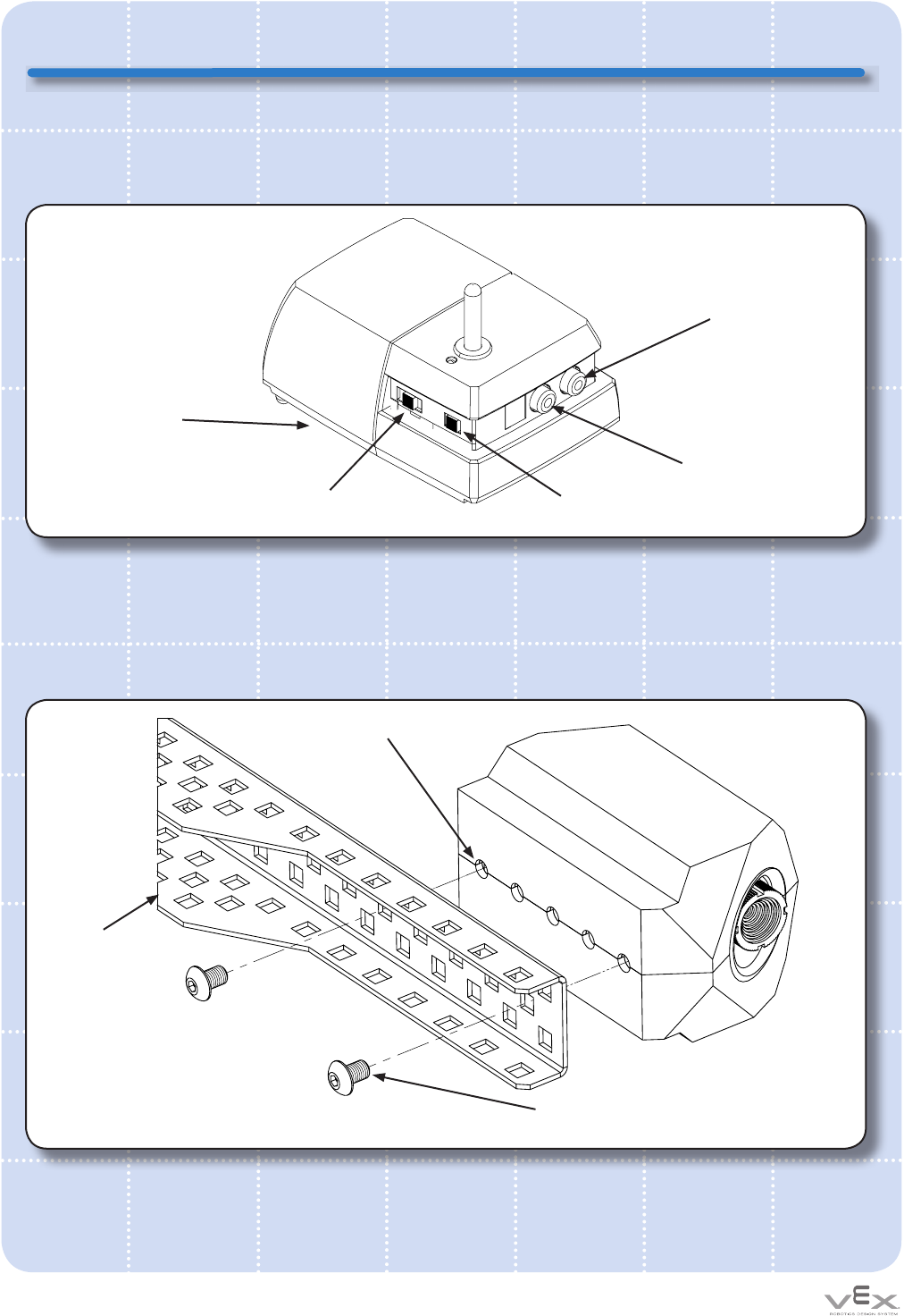
Connect the Camera Receiver to a Television (not included) using the RCA Cable provided in
the kit. Make sure the yellow connector is connected to the “Video” port on the Receiver, and
the television, and the white connector is connected to the “Audio” port on the Receiver and the
television.
Once the Receiver has batteries installed and is connected to the TV, it is time to mount the
Camera to your robot. The Camera has a row of (5x) threaded mounting holes on its bottom.
These holes can be used to attach to Camera unit to any VEX structural component. The
image below shows an example of camera mounting using the 2 Mounting Screws provided in
this kit.
Mounting
Holes
Battery Case
(underneath unit)
Channel Selector
Switch
Robot
Structure
Mounting
Screws
White Audio
Port
Yellow Video
Port
On/Off
Switch

Auxiliary Accessories
Inventor’s Guide insert Color Camera Kit • 3
accessories
Color Camera Kit, continued
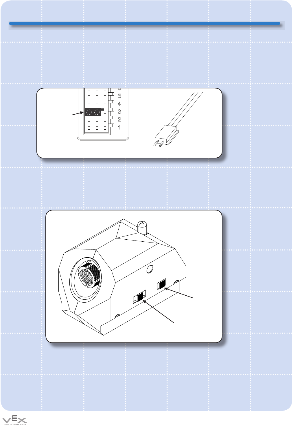
The Camera draws power from a motor port on a VEX Microcontroller plug the 2-prong
connector into a 3-pin socket so that the connector is against the at edge (not the keyed edge)
as shown. The key on the connector should NOT be inserted into the key of the socket.
Note: The robot must be turned “on” for the Camera to receive power. You cannot have the
robot turned “off” and still operate the camera.
Once the Camera is mounted and connected to power, it is time to turn the system on. Ensure
that both the Camera unit and the Receiver are set to the same channel. (Each of these units
has a “Channel Selector Switch”, set these to the same number). Turn both units “on”, and
set the TV to the correct video input channel (this will vary, depending on the TV).
VEX Microcontroller
Motor Parts
Camera 2-prong
connector
Connector sits
against this
“at edge”
8
7
6
5
4
3
2
1
Channel Selector
Switch
On/Off
Switch

Auxiliary Accessories
Inventor’s Guide insertColor Camera Kit • 4
accessories
Color Camera Kit, continued
Camera Troubleshooting Guide:
Problem:
The LED light on the Camera Receiver is not “on”.
Solutions:
1. Check your batteries to see if they have been installed correctly.
2. Check that batteries are charged.
3. Check that the power switch is in the “on” position.
Problem:
The LED light on the Camera Unit is not “on”.
Solutions:
1. Check that the power switch on the Camera is in the “on” position.
2. Check that the Camera 2-prong connector is correctly connected.
3. Check that the robot is turned “on” and has fresh batteries.
Problem:
The LED light is activated on both the Camera Receiver and the Camera Unit, but I get no
video.
Solutions:
1. Check that the RCA Video Cable is correctly attached to your television and to the
Camera Receiver.
2. Check that your television is on the correct input channel (refer to your TV manual).
3. Check that the “Channel Selector Switch” on the Camera Unit and Receiver are set to
the same number.
Problem:
The video quality is poor.
Solutions:
1. Check that the Camera is not too far away from the Receiver. The Camera will only
work within a certain distance from the Receiver.
2. There may be interference from outside sources. Try changing the channel on the
Camera and the Receiver to a different number, and see if the video quality improves.
Note, the Camera and Receiver must both be set to the same channel.
3. The RCA Video Cable may be slightly disconnected, try disconnecting and reinstalling
the cable for a better connection.
4. The RCA Cable may be damaged or broken. Try an alternate RCA cable.
5. The battery level on your robot or Camera Receiver is low, replace the batteries.

Auxiliary Accessories
Inventor’s Guide insert Color Camera Kit • 5
accessories
Color Camera Kit, continued
Warning:
Changes or modications to this unit not expressly approved by the party responsible for
compliance could void the user’s authority to operate the equipment.
Note
This equipment has been tested and found to comply with the limits for a Class B digital
device, pursuant to Part 15 of the FCC Rules. These limits are designed to provide
reasonable protection against harmful interference in a residential installation. This
equipment generates, uses and can radiate radio frequency energy and, if not installed
and used in accordance with the instructions, may cause harmful interference to radio
communications.
However, there is no guarantee that interference will not occur in a particular installation.
If this equipment does cause harmful interference to radio or television reception, which
can be determined by turning the equipment off and on, the user is encouraged to try to
correct the interference by one or more of the following measures:
• Reorient or relocate the receiving antenna.
• Increase the separation between the equipment and receiver.
• Connect the equipment into an outlet on a circuit different from that to which the
receiver is connected.
• Consult the dealer or an experienced radio/TV technician for help.