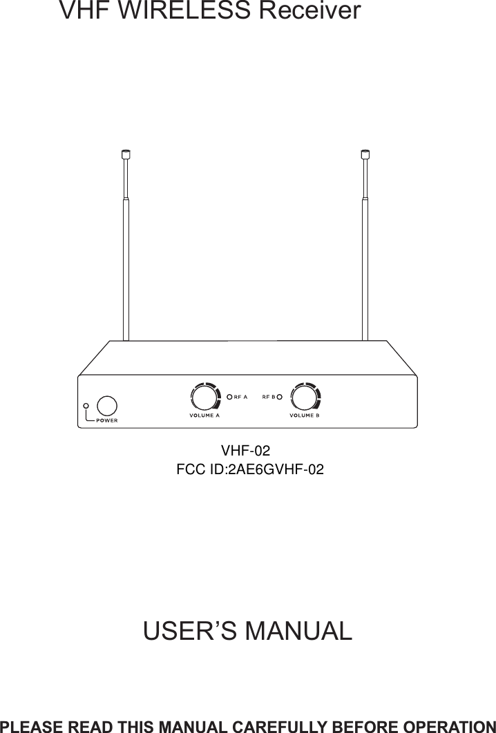
Innovative Concepts and Design VHF-02 Wireless Receiver User Manual

INNOVATIVE CONCEPTS AND DESIGN LLC Wireless Receiver

User Manual

USER’S MANUALPLEASE READ THIS MANUAL CAREFULLY BEFORE OPERATIONVHF   WIRELESS ReceiverVHF-02FCC ID:2AE6GVHF-02
1. Power Indicator2. ON/OFF Switch3. Volume Control4. RF Indicator1. Connect one end of supplied 6.35mm to 6.35mm plug audio cable  into AF OUT jack on rear panel of the receiver. Connect the other end of the audio cable into "MIC IN" or "AUX IN" of amplifier or mixer.2. Connect DC plug of supplied AC/DC adapter to DC INPUT jack on rear panel of the receiver. Connect AC plug of AC/DC adapter to mains power socket.  3. Press ON/OFF button on front panel to turn on the receiver.4. Extend antenna fully. 5. Turn on the transmitter. RF indicator on receiver will light. 6. Adjust receiver volume and your amplifier or mixer volume to suitable level.RECEIVERParts DescriptionDualChannel FrontRearOperation1423 345 67SPECIFICATIONS ReceiverFrequency Range:        177.6MHz186.6MHz or 198.6MHz204.6MHzFrequency Stability:      10PPMSensitivity:                     -92dBmFrequency Response:  80Hz~12KHzAudio Output Level:      150mV(RMS)S/N:                               >75dBDistortion:                      <1%Power Supply:               DC 9V 200mACurrent Consumption:   150mATransmitterFrequency Stability:       10ppmRF Output:                     <10mWModulation:                    FMMax Deviation:               ±75KHzHarmonic Suppression : >45dBPower Supply:               3V(2xAA batteries)Current Consumption:   100mA5. 1/4" unbalanced output jack6. DC input jack7. Antenna7Frequency Range:        177.6MHz186.6MHz or 198.6MHz204.6MHz
14OperationParts DescriptionBELT PACK TRANSMITTER23Parts DescriptionHANDHELD MIC1. Grille(Capsule inside)2. Power/low battery Indicator3. Power ON/OFF/MUTE Switch4. Battery Compartment/Cover14Operation231. Open battery cover. Install the provided 2pcs 1.5V AA batteries and then close the cover. Pay attention to the correct polarity.Push power switch to ON position, power indicator should flash once briefly indicating that the transmitter has sufficient power. If the power LED indicator stays on, it indicates that the battery has insufficient power and should be changed. If the power LED indicator does not light at all and the transmitter does not work, it indicates the battery is dead and you should change the battery.If the microphone is not going to be used for any length of time, push power switch to OFF position and remove the battery.2. 3. Now receiver RF indicator should light(Please confirm frequency of microphone same as that of receiver before operation).4. Push power switch to MUTE position to mute the sound.5. During operation if power indicator lights red, this indicates the battery is Iow. Please replace new battery.6. 1. Open battery cover. Install the provided 2pcs 1.5V AA batteries and then close the cover. Pay attention to the correct polarity.2. Insert headset MIC or clip-on MIC plug into MIC IN jack. And turn plug clockwise to lock the headset MIC.3. Slide power switch to ON position, power indicator should flash once briefly indicating that the transmitter has sufficient power. If the power LED indicator stays on, it indicates that the battery has insufficient power and should be changed. If the power LED indicator does not light at all and the transmitter does not work, it indicates the battery is dead and you should change the battery.5. Slide power switch to MUTE position to mute the sound.6. If the transmitter is not going to be used for any length of time, push the power switch to OFF position and remove the battery.4. Now receiver RF indicator should light. Please confirm frequency of transmitter is same as receiver before operation.1. Power ON/OFF/MUTE Switch2. Power/low battery Indicator3. MIC in jack4. Battery Compartment/Cover
NOTE: This equipment has been tested and found to comply with the limits for a Class B digital device, pursuant to part 15 of the FCC Rules. These limits are designed to provide reasonable protection against harmful interference in a residential installation. This equipment generates, uses and can radiate radio frequency energy and, if not installed and used in accordance with the instructions, may cause harmful interference to radio communications. However, there is no guarantee that interference will not occur in a particular installation. If this equipment does cause harmful interference to radio or television reception, which can be determined by turning the equipment off and on, the user is encouraged to try to correct the interference by one or more of the following measures: —Reorient or relocate the receiving antenna. —Increase the separation between the equipment and receiver. —Connect the equipment into an outlet on a circuit different from that to which the receiver is connected. —Consult the dealer or an experienced radio/TV technician for help. Thisdevicecomplieswithpart15oftheFCCrules.Operationissubjecttothefollowingtwoconditions:(1)thisdevicemaynotcauseharmfulinterference,and(2)thisdevicemustacceptanyinterferencereceived,includinginterferencethatmaycauseundesiredoperation.Changesormodificationstothisunitnotexpresslyapprovedbythepartyresponsibleforcompliancecouldvoidtheuser'sauthoritytooperatetheequipment.

Navigation menu