Innovative Control Systems HWHY-660017 RFID Controller activates LF RFID Tags at Portals of egress and responds as per customer needs User Manual 1 UM25 outsidecover
Innovative Control Systems Inc RFID Controller activates LF RFID Tags at Portals of egress and responds as per customer needs 1 UM25 outsidecover
Exhibit D Users Manual per 2 1033 b3
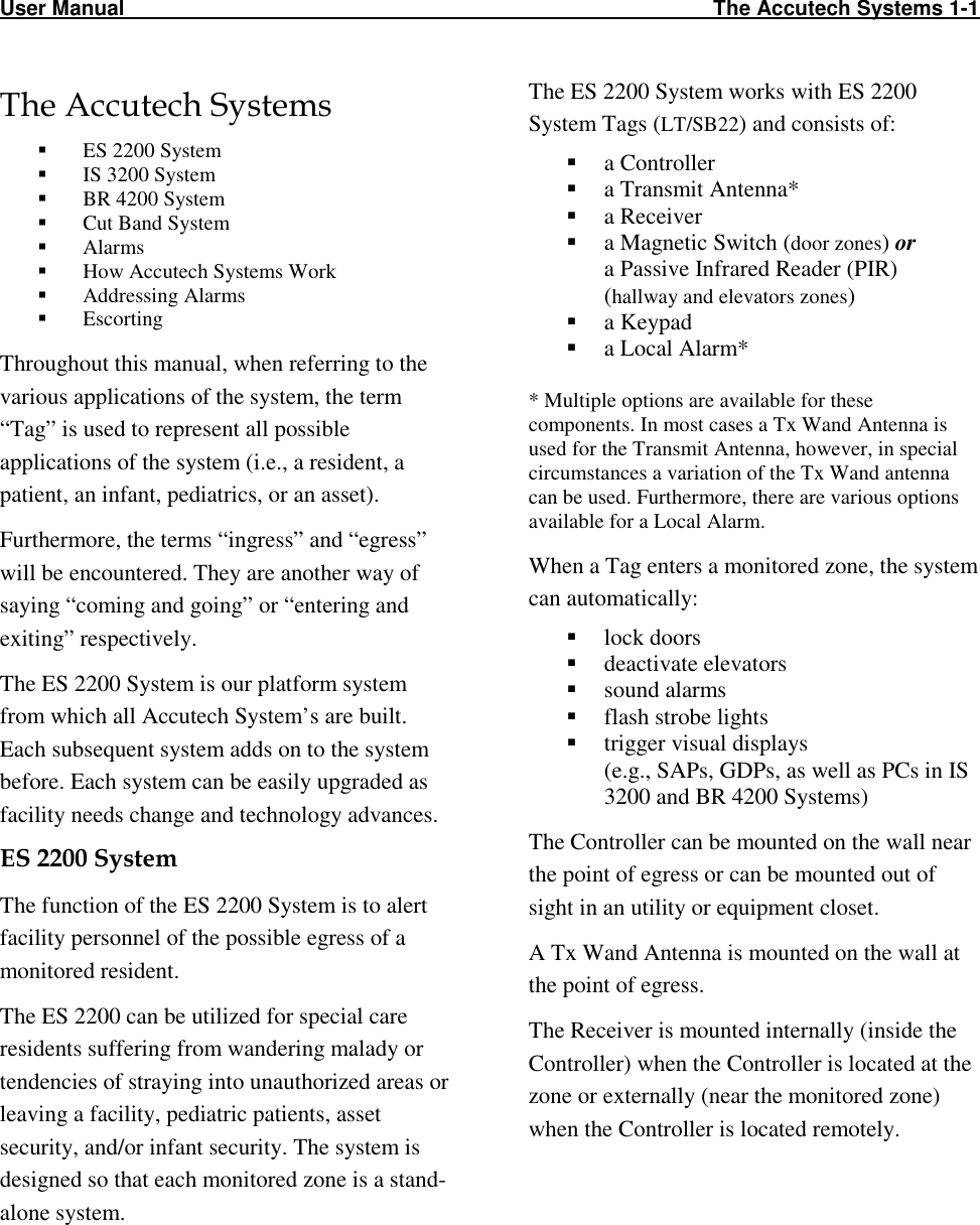
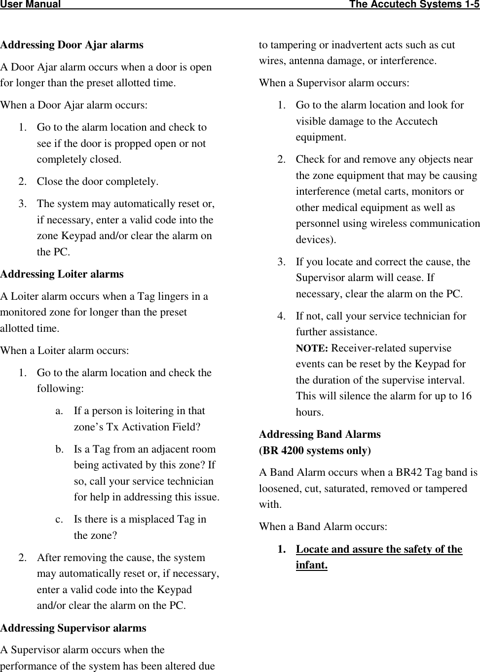

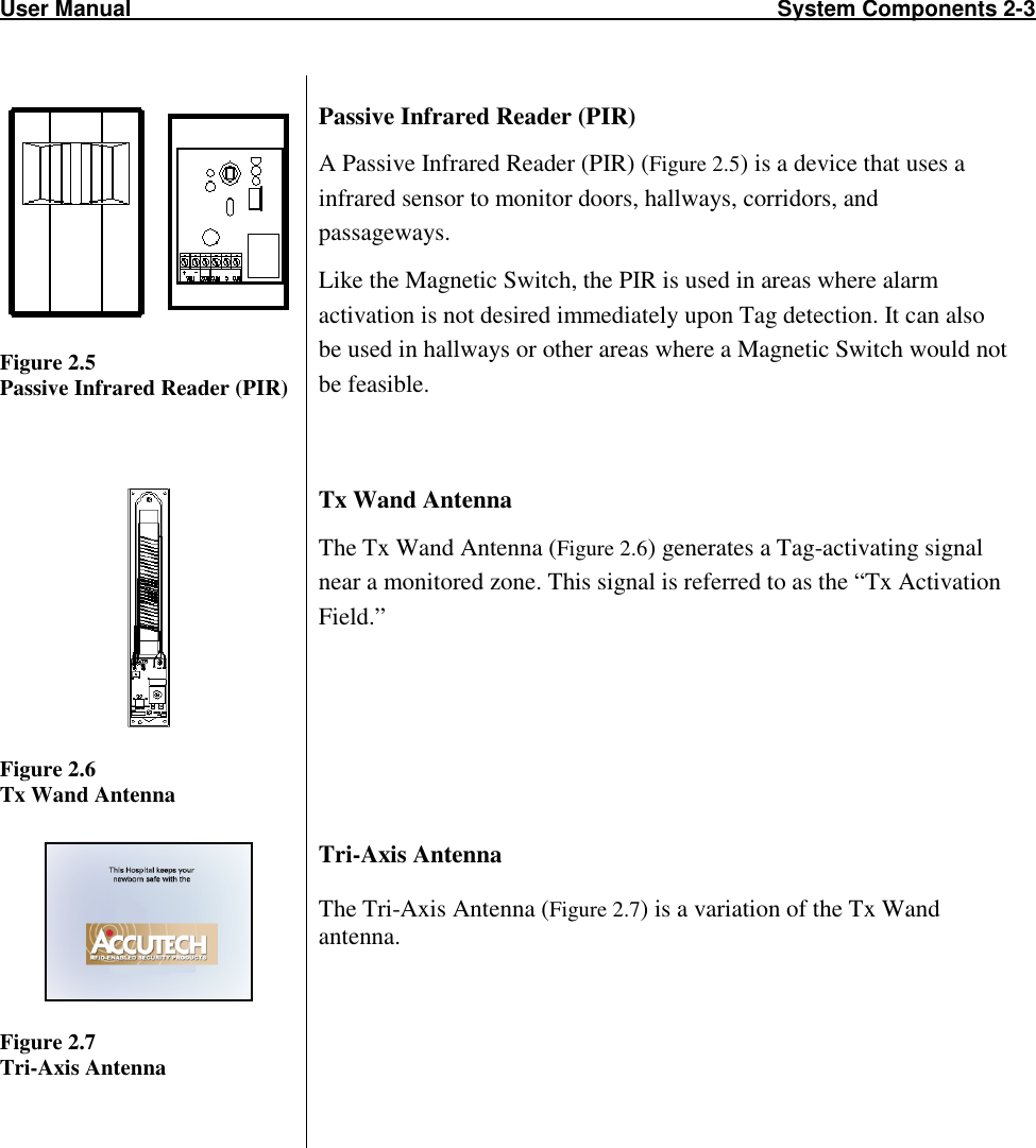
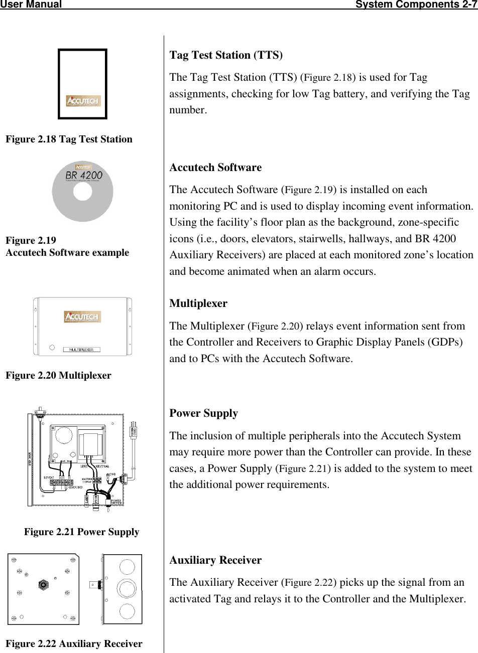

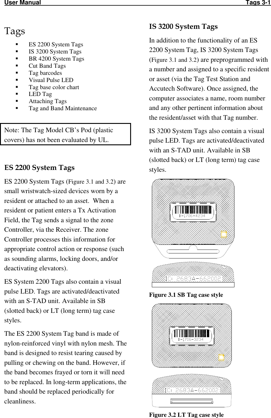


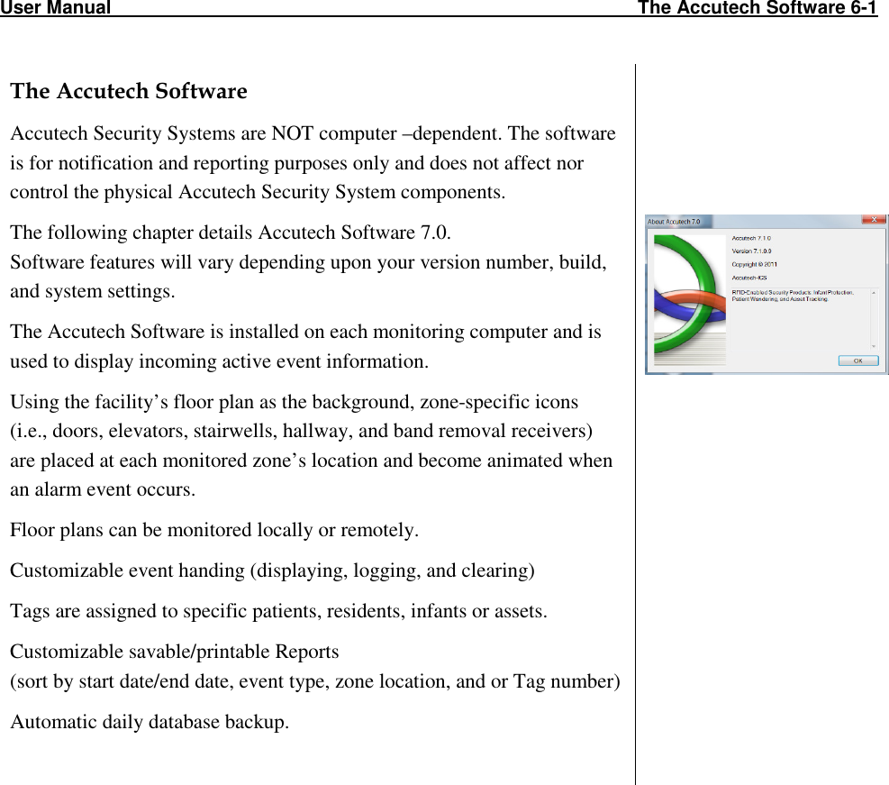
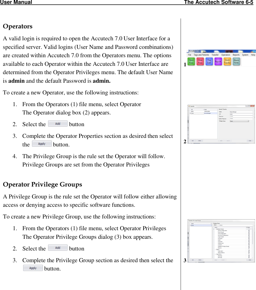
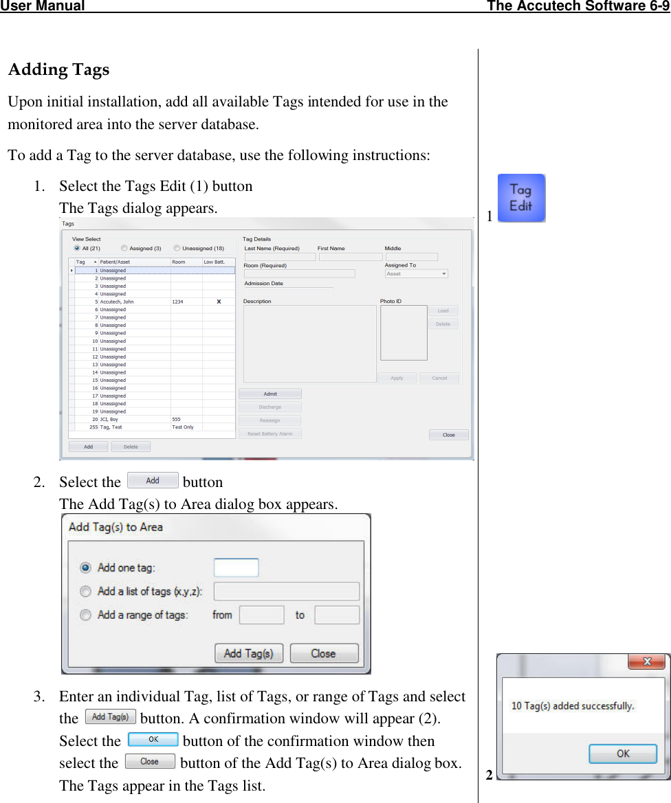
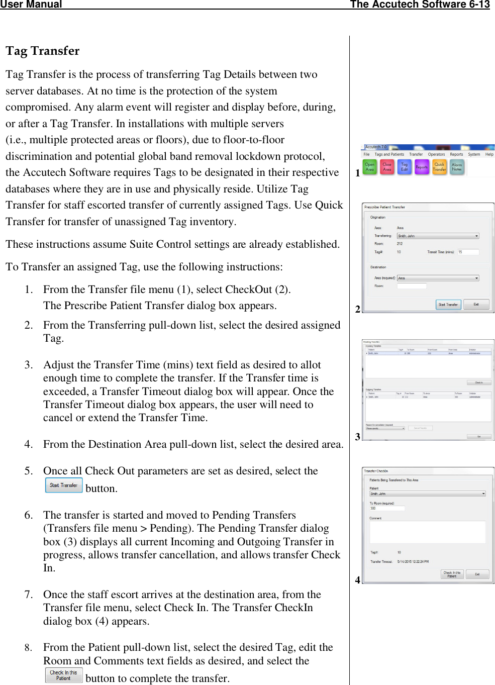
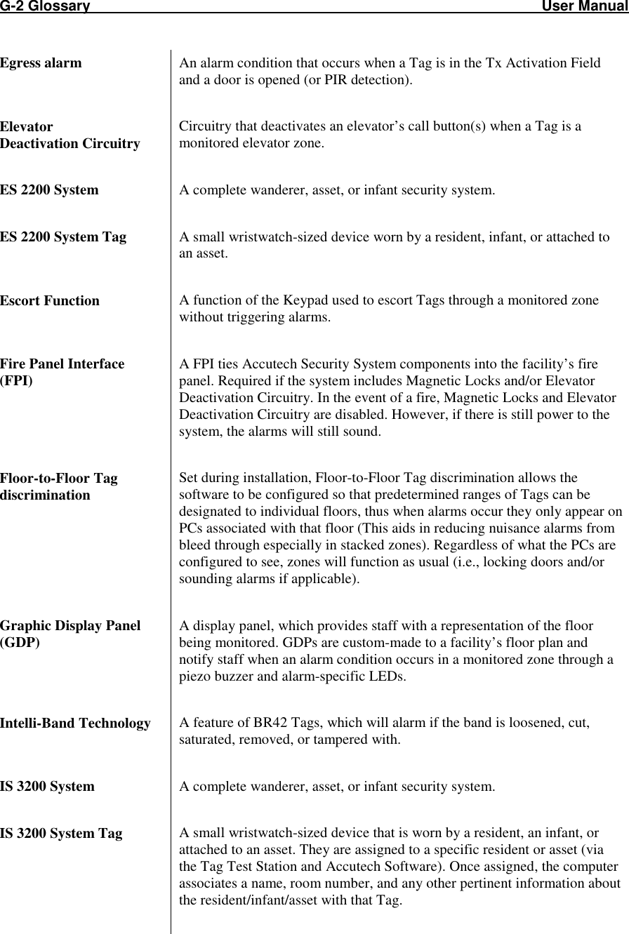
![User Manual The Keypad 5-1 The Keypad (KP-103) Programming Programming Initiating a Keypad Reset/Escort Programming How to enter user codes How to delete user codes How to set the relay time How to set the installer code The Keypad (Part # 650209) provided by Accutech (the KP-103) is used to escort residents through a monitored zone and to reset zone equipment once an alarm has occurred. The Keypad (KP-103) Programming the Keypad is, in simple terms, providing it with a set of instructions on how to react in various contingencies. The Keypad must be programmed as soon as all installation and wiring have been completed. Later on, as changes take place, partial or full reprogramming may be carried out as many times as necessary. The Keypad has three LED indicators. See Table 5.1 for their functions during normal operation. Table 5.1 Keypad LED Indicators LED Status Function Green On Output relay is active Yellow On Monitors power input Red On LC Unit is in alarm * During programming, the green LED functions differently. Initiating the First Relay (Reset/Escort) To initiate the first relay, enter a valid user code and press the [#] key. The green LED will light. Accutech Default is . Keypad Resets are used to reset zone equipment after an alarm has been addressed. When you initiate a Keypad Reset, all zone equipment and alarms will be reset. However, if the alarm condition is not properly corrected, the alarm will resume. The Keypad’s Escort function is used to escort Tags through a monitored zone without triggering alarms. When you initiate the Escort function, for the duration of the Escort time, you will be able to escort the Tag through the door, hallway, or use an elevator without triggering alarms. Initiating the Second Relay (Anti-Tailgate) To initiate the second relay, enter a valid user code and press the [#] key. The green LED will light. Accutech Default is . The second relay is an anti-tailgate feature that will allow unimpeded passage through the exit point without triggering an alarm; however, any banded tailgater attempting to subsequently pass-through will trigger an alarm event.](https://usermanual.wiki/Innovative-Control-Systems/HWHY-660017/User-Guide-3930142-Page-51.png)
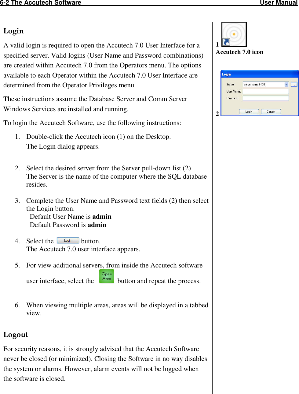
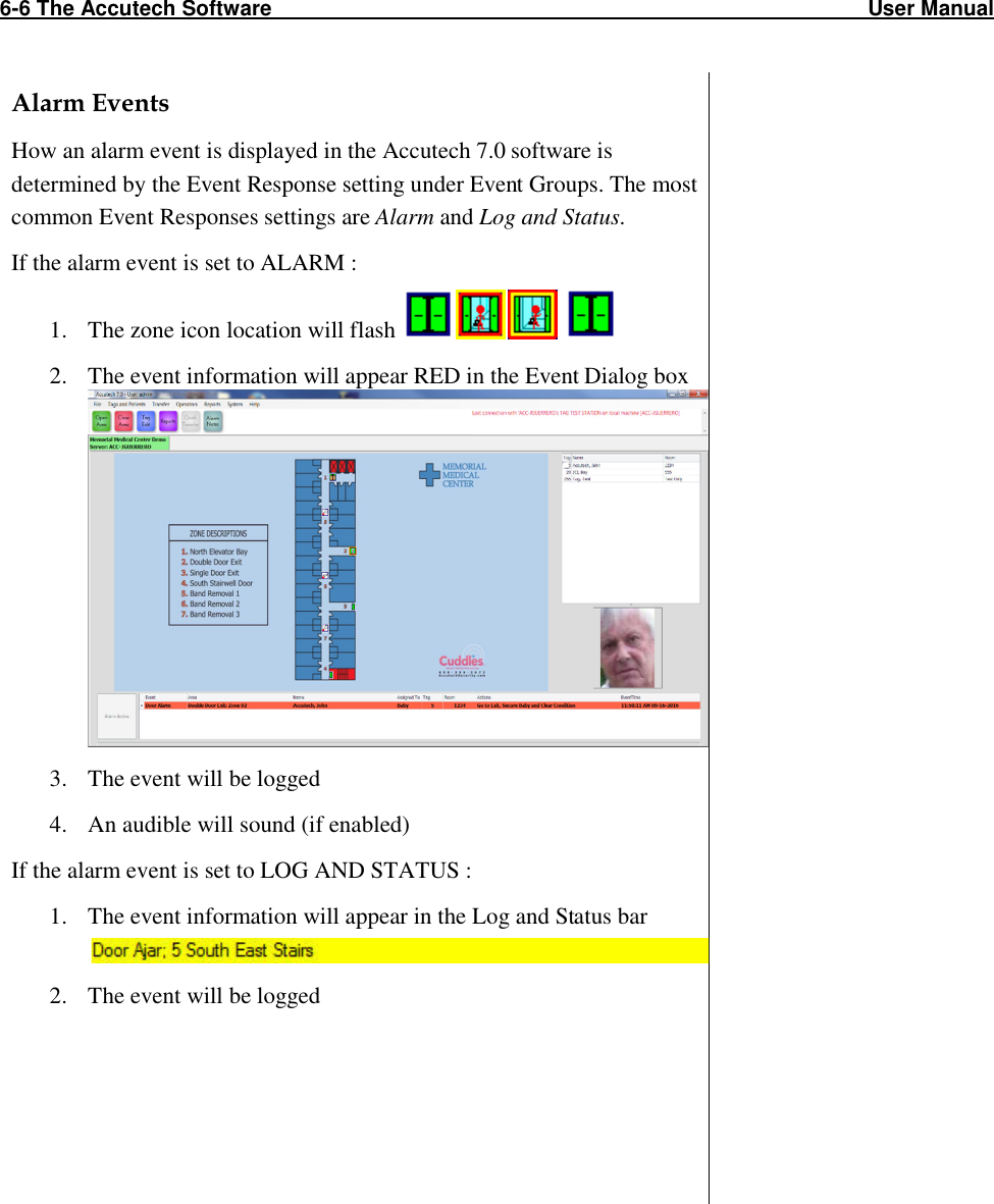
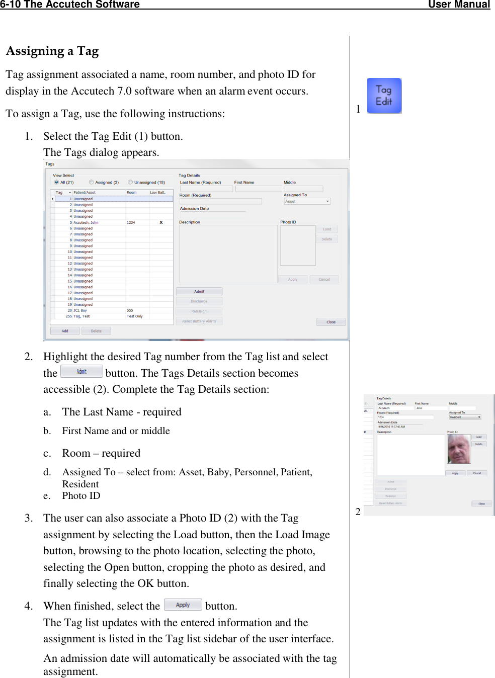
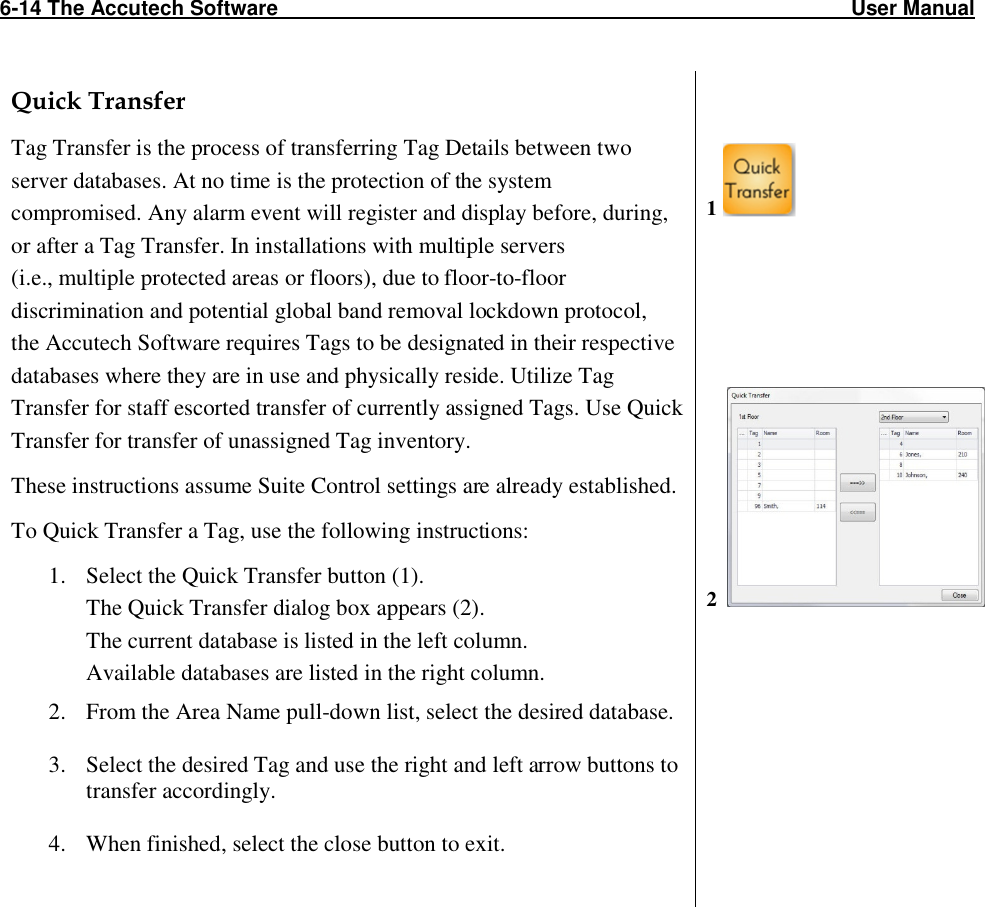
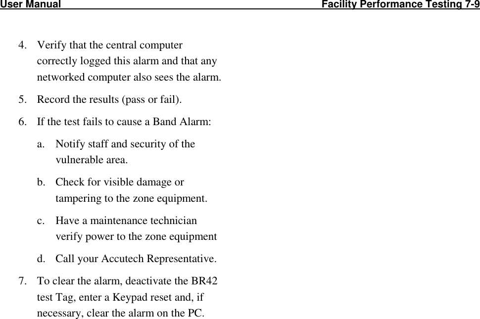
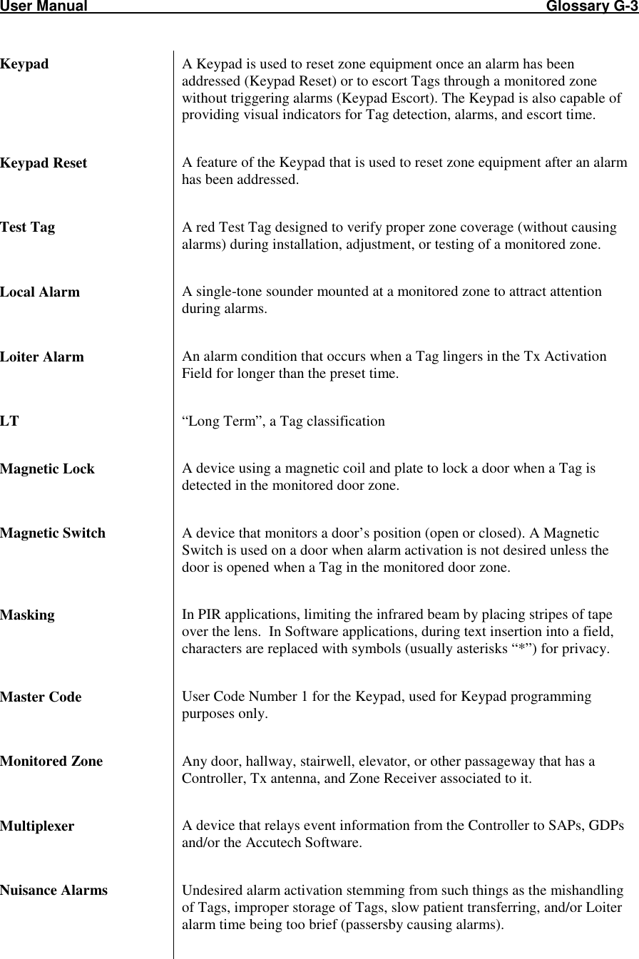
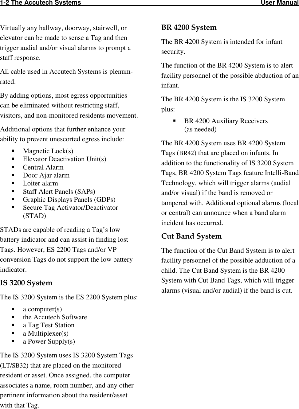
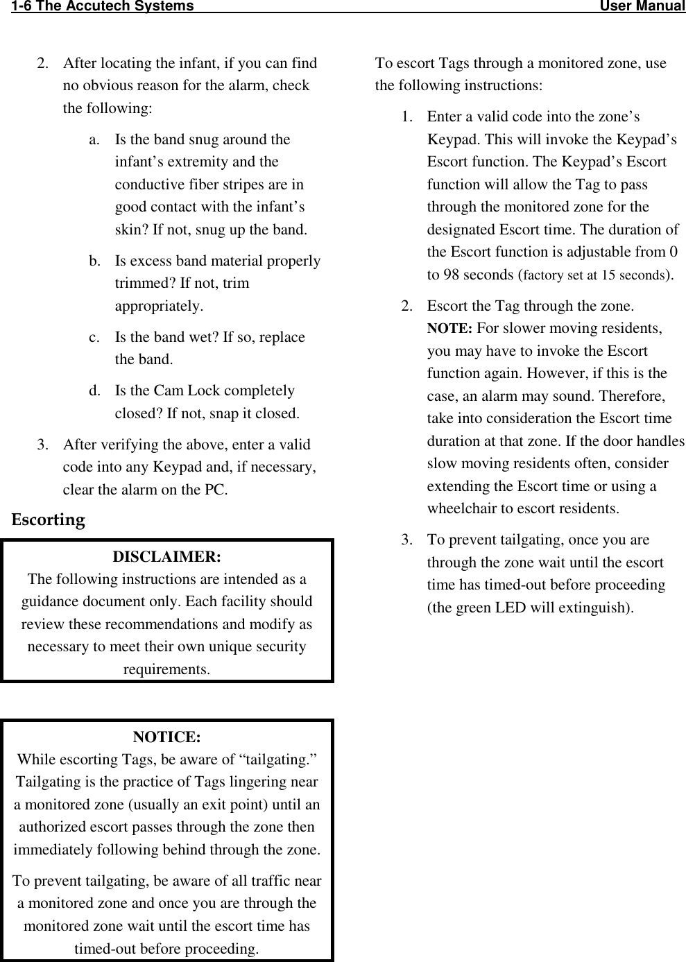
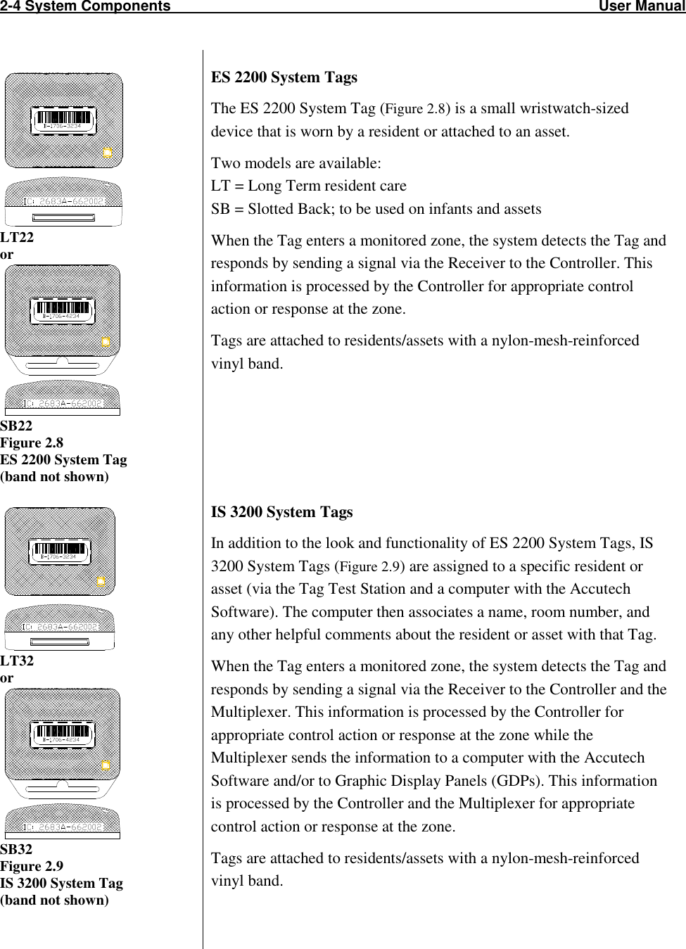
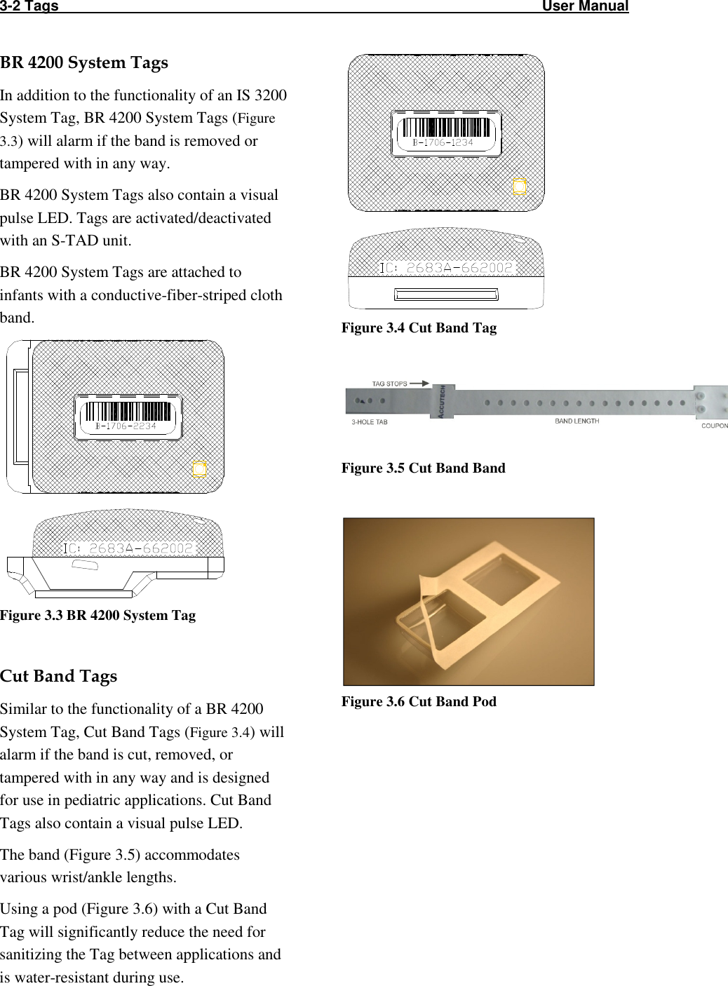
![5-2 The Keypad User Manual How to enter user codes (First Relay) Note: First Relay user numbers are two digits and range from 01-99. 1. Enter the installer code [1][1][1][1][*] to enter program mode. You will hear two beeps. 2. Enter [1] to select relay 1 3. Then enter the desired user number (for example 02) then enter the new user code (for example 5555) followed by the [#] key. You will hear two beeps. 4. Continue programming for additional user codes as desired (for example 03, 9999, #). 5. When finished, enter [*] to exit program mode and return the Keypad normal operation mode. How to delete user codes (First Relay) 1. Enter the installer code [1][1][1][1][*] to enter program mode. You will hear two beeps. 2. Enter [1] to select relay 1 3. Then enter the desired user number (for example 02) then the [#] key. You will hear two beeps. 4. Continue deleting additional user codes as desired (for example 03, #). 5. When finished, enter [*] to exit program mode and return the Keypad normal operation mode. (enter programming mode) (selects relay 1) (selects user code 02) (selects 5555 as the code) (exits programming mode) (enter programming mode) (selects relay 1) (selects user code 02) (deletes user code 02) (exits programming mode)](https://usermanual.wiki/Innovative-Control-Systems/HWHY-660017/User-Guide-3930142-Page-52.png)
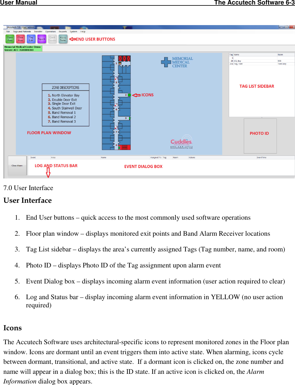
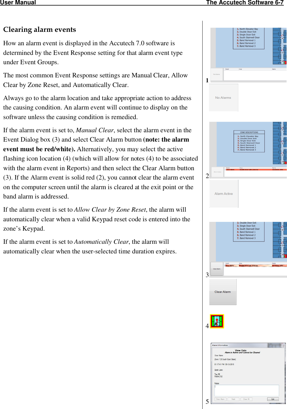
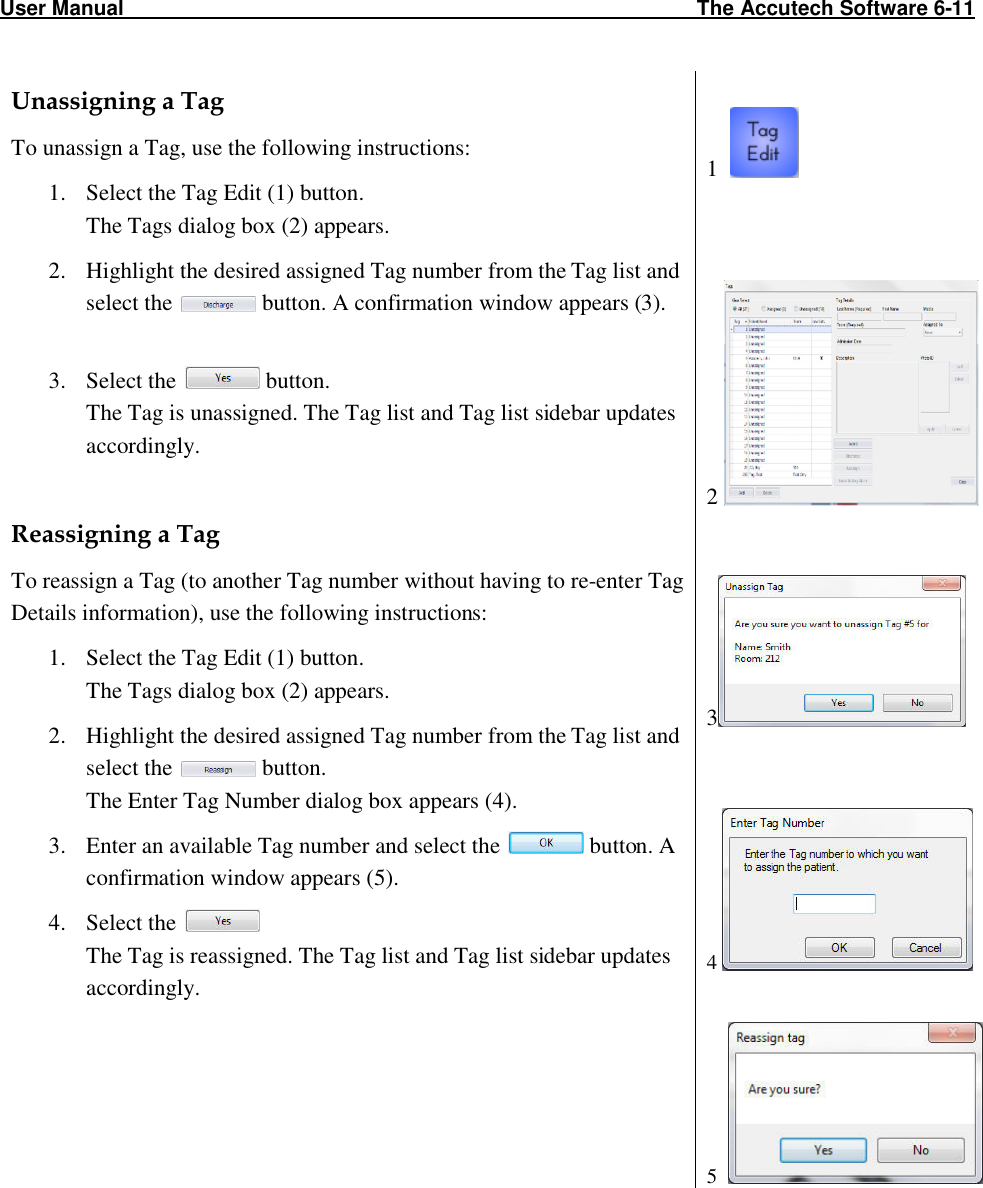
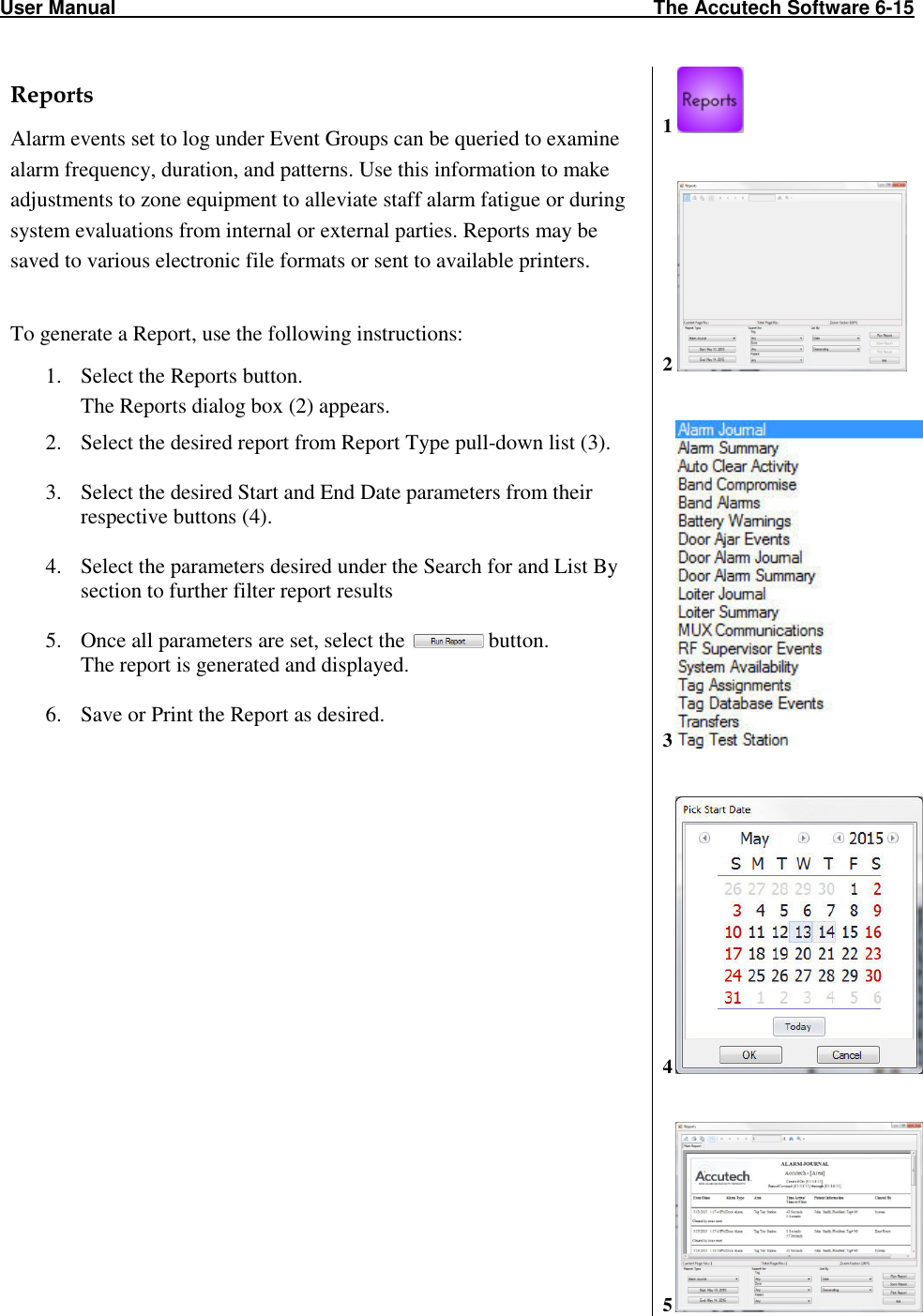
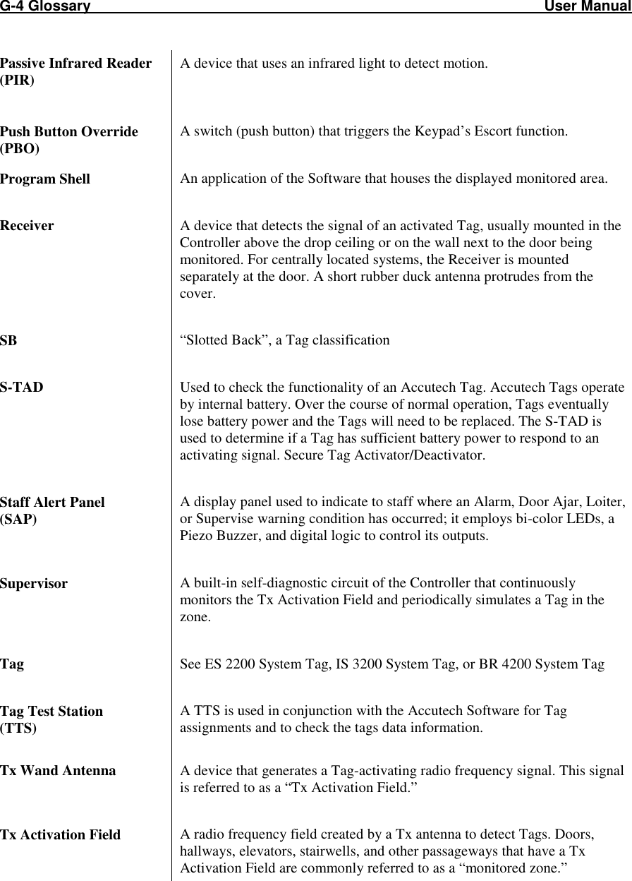
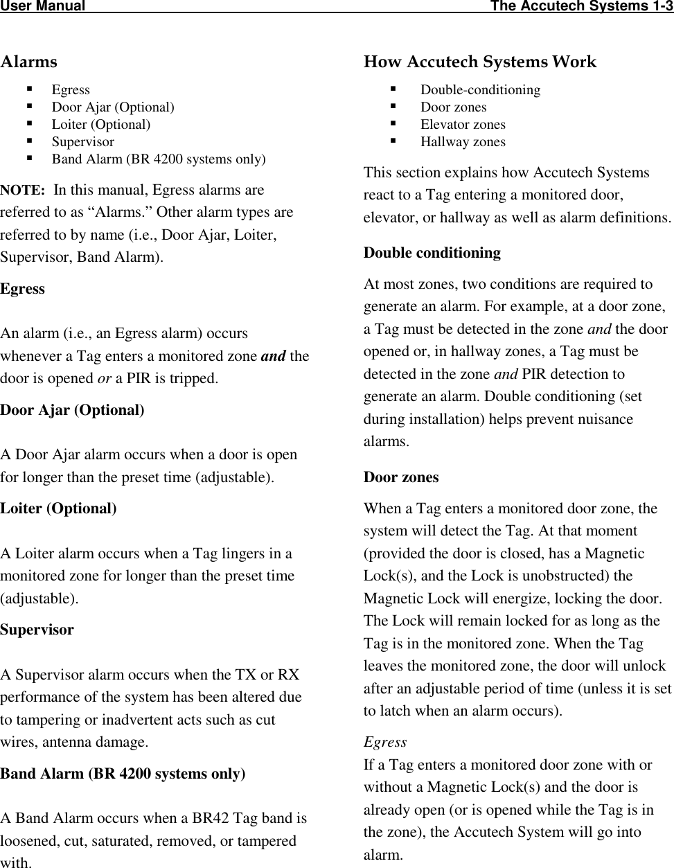
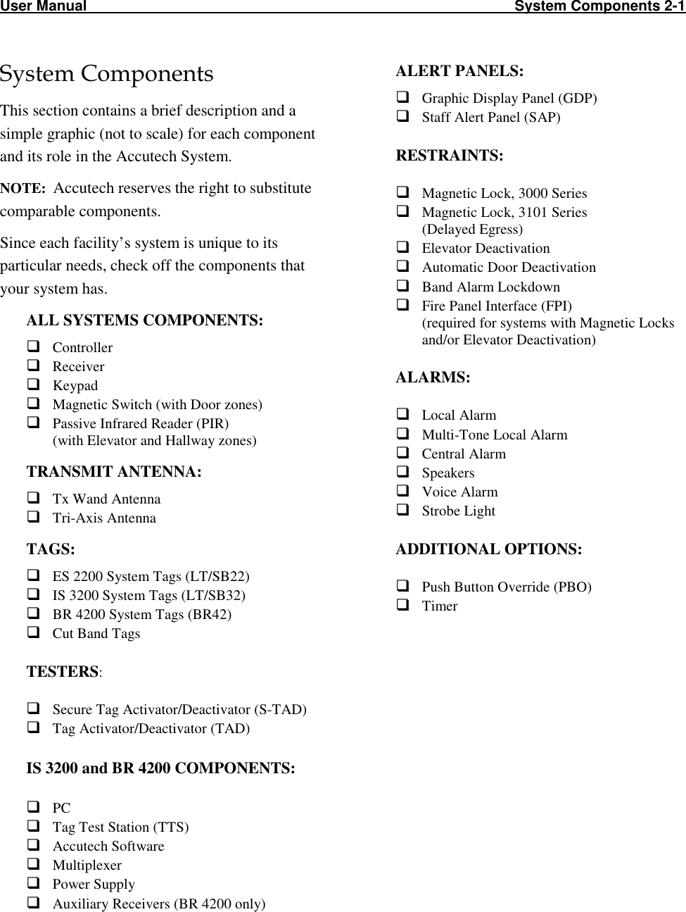
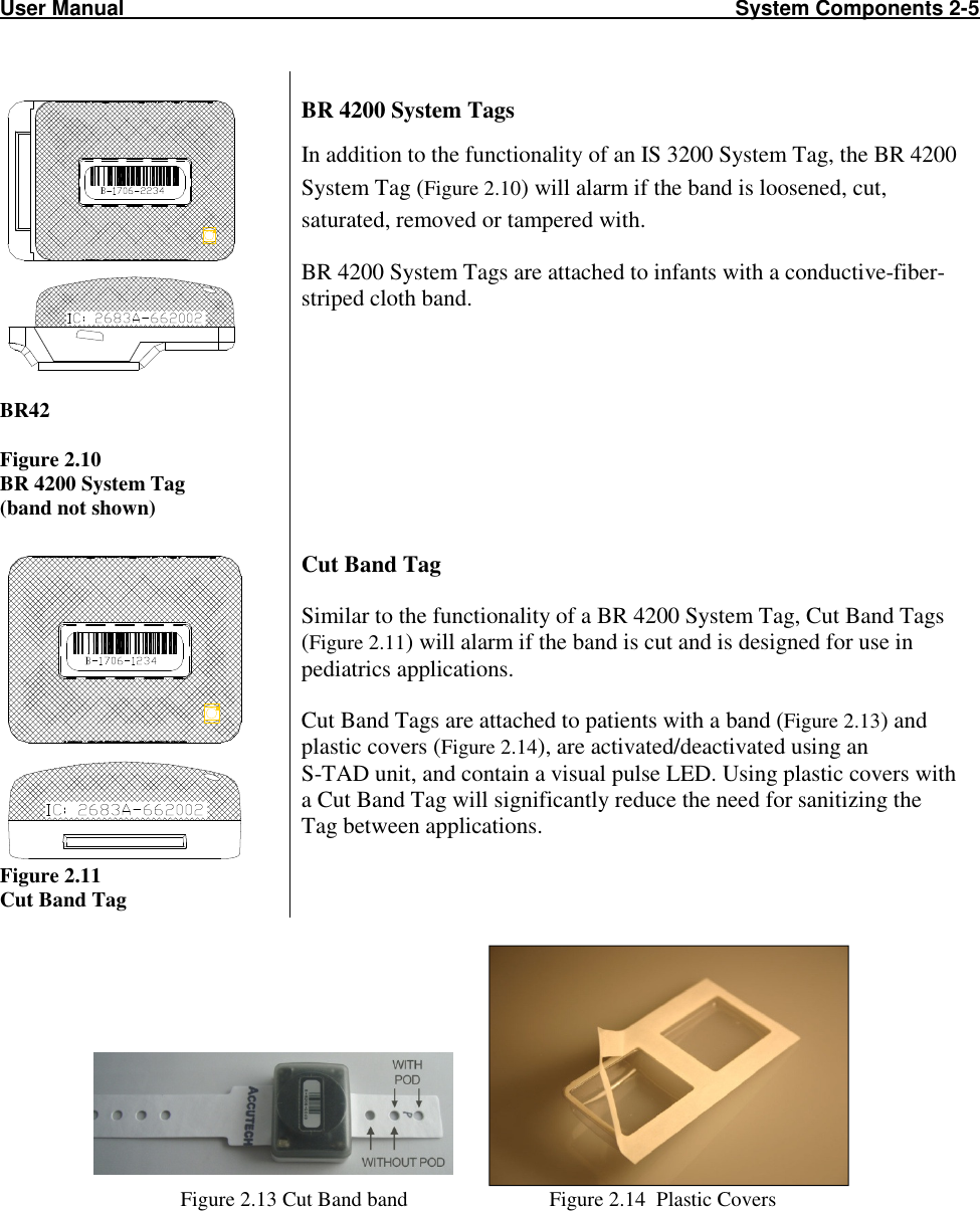
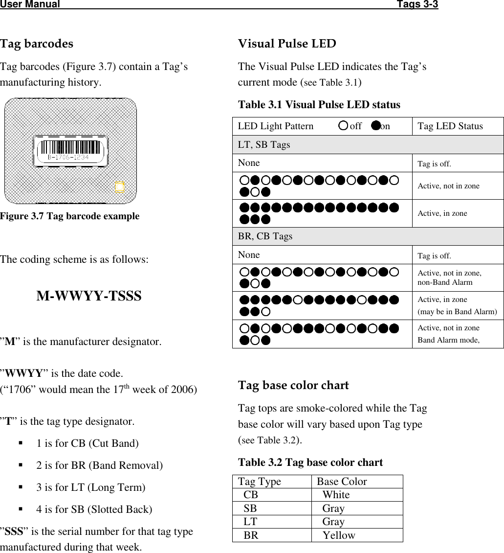
![User Manual The Keypad 5-3 How to set the relay time (First Relay) Note: The relay time is factory set to 15 seconds by Accutech. To change the relay time: 1. Enter the installer code [1][1][1][1][*] to enter program mode. You will hear two beeps. 2. Enter [4][0] then the desired relay time (1-999 seconds), then the [#] key. You will hear two beeps. 3. Enter [*] to exit program mode and return the Keypad normal operation mode. (enter programming mode) (selects timer for relay 1) (sets timer to 15 seconds) (exits programming mode)](https://usermanual.wiki/Innovative-Control-Systems/HWHY-660017/User-Guide-3930142-Page-53.png)
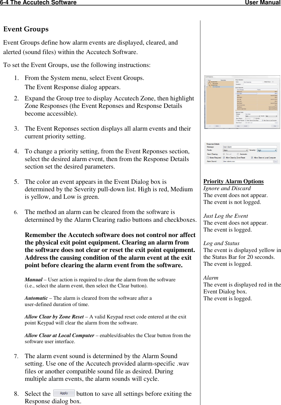
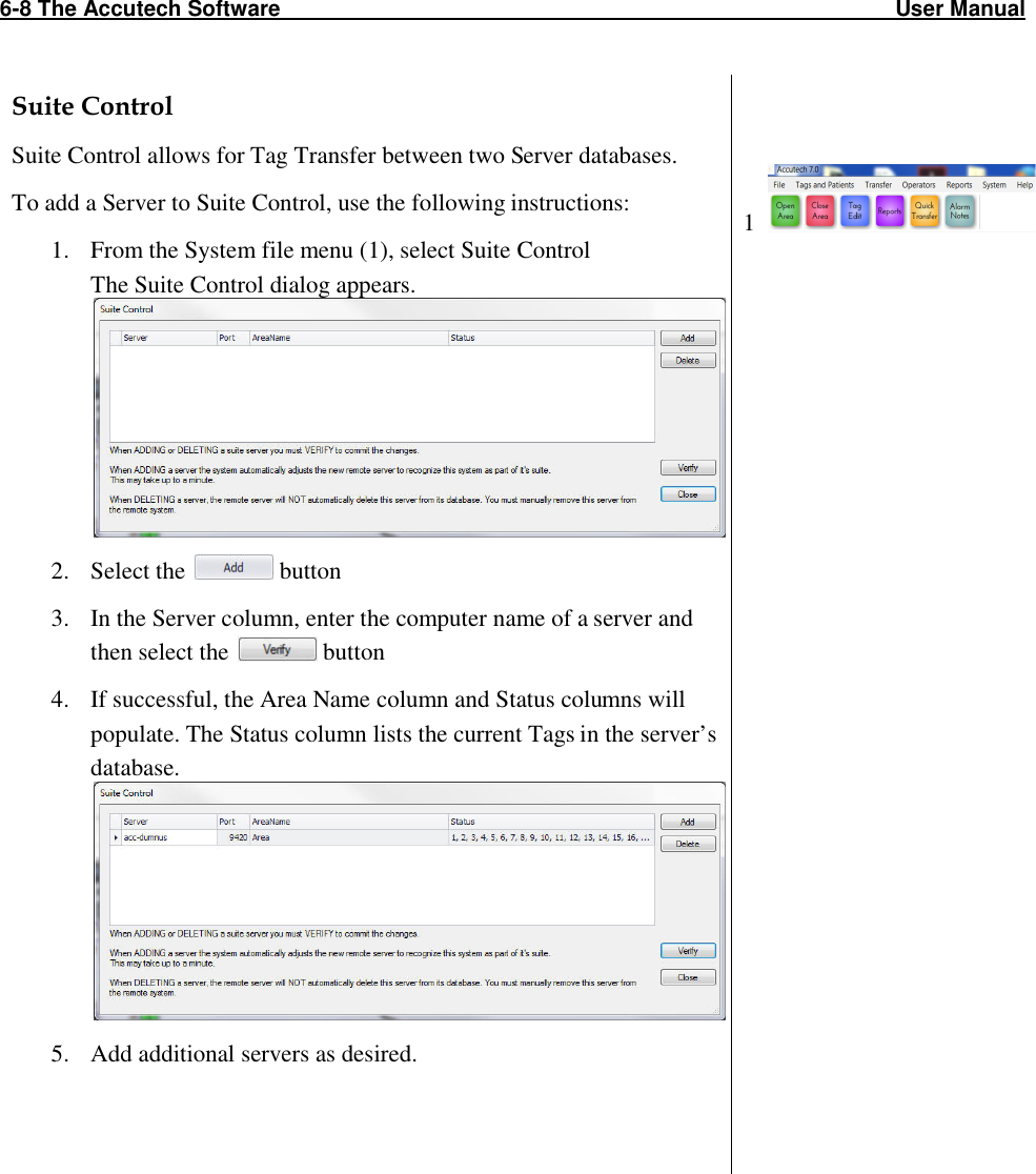
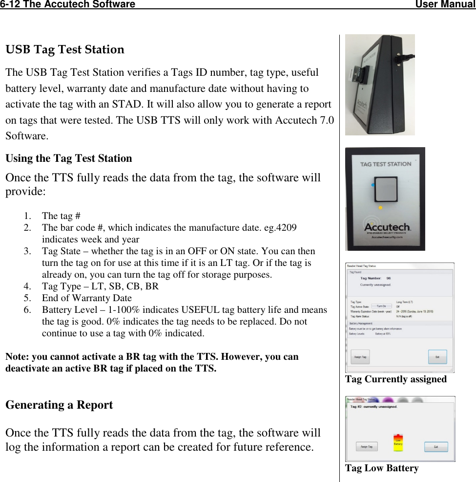
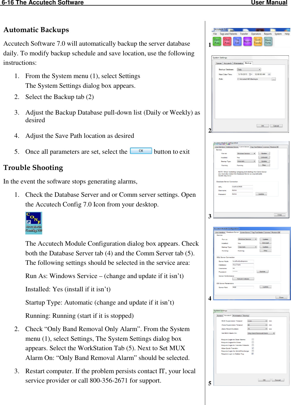
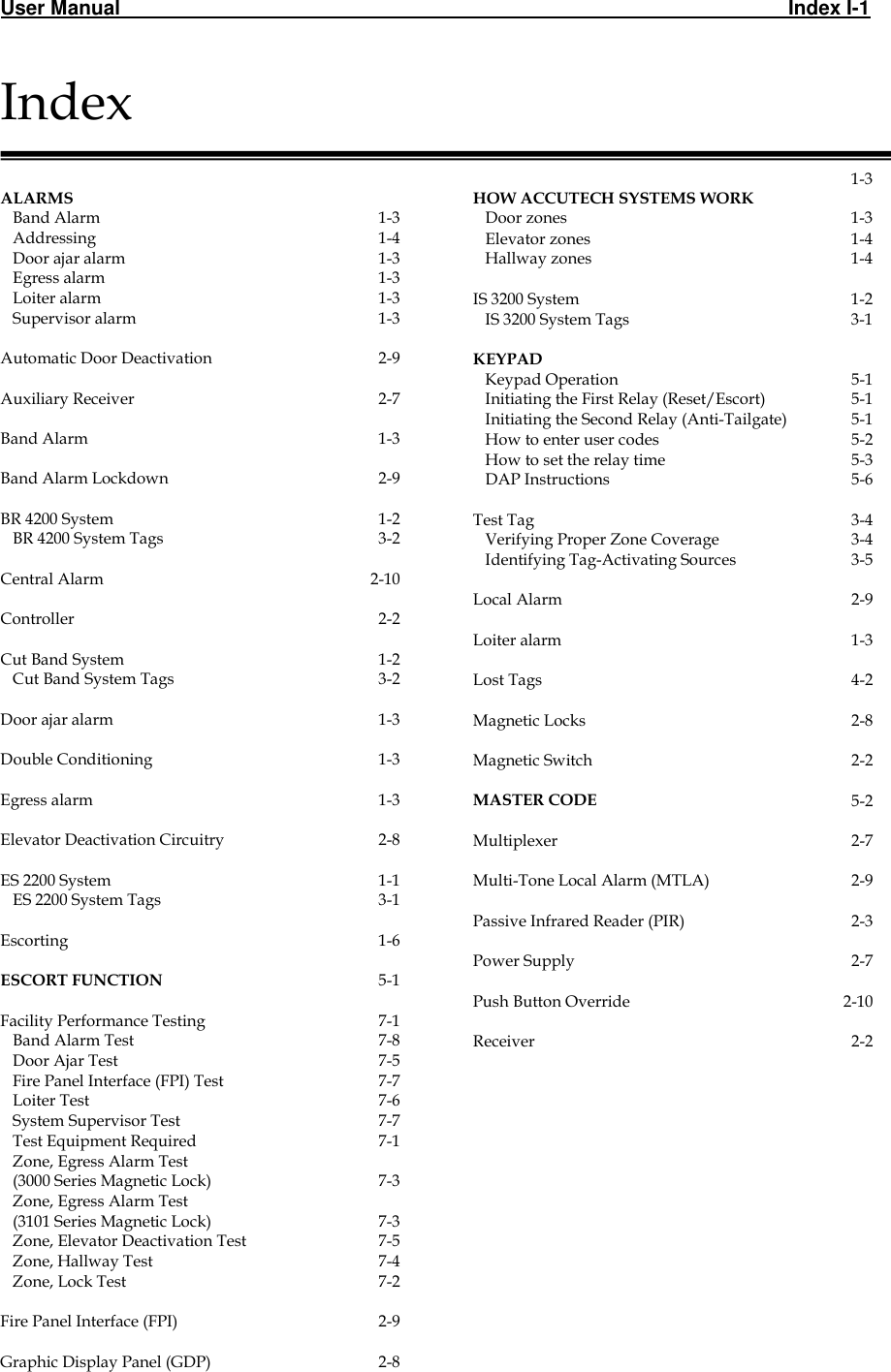
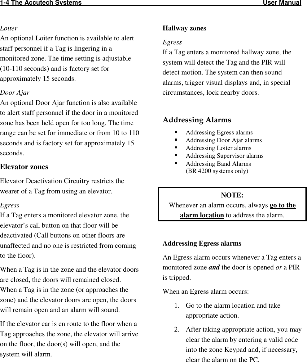
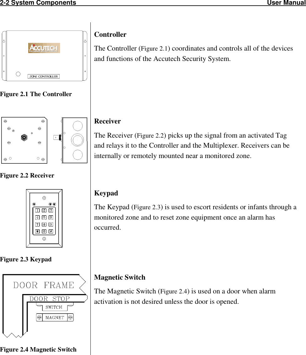
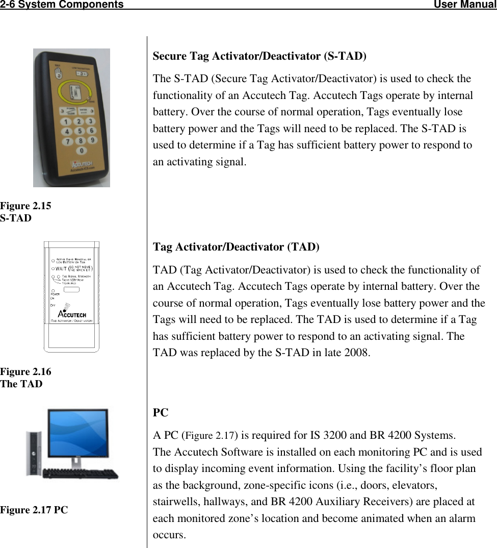
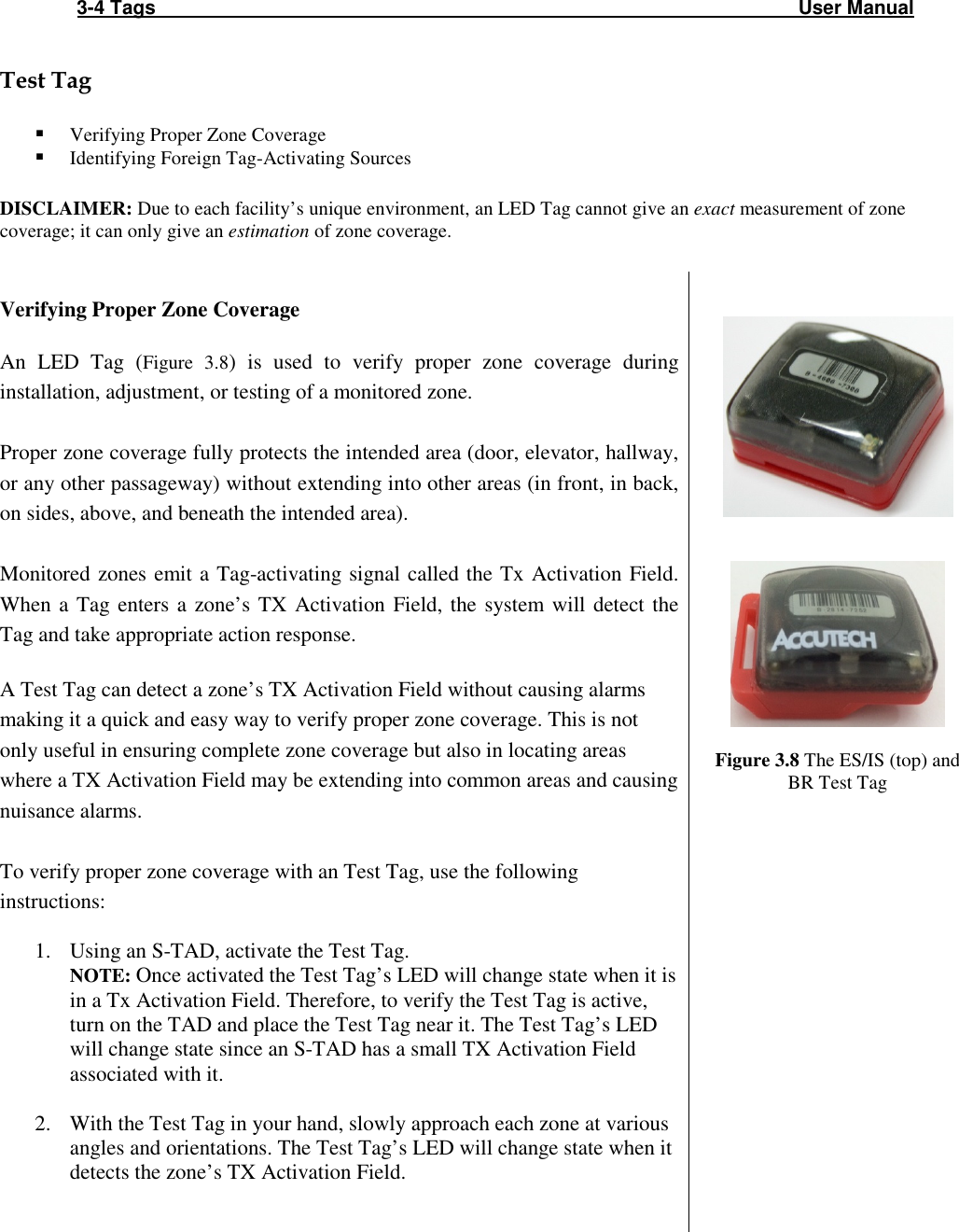
![5-4 The Keypad User Manual How to enter user codes (Second Relay) Note: Second Relay user numbers are one digit and range from 1 to 9. 1. Enter the installer code [1][1][1][1][*] to enter program mode. You will hear two beeps. 2. Enter [2] to select relay 2 3. Then enter the desired user number (for example 2) then enter the new user code (for example 5555) followed by the [#] key. You will hear two beeps. 4. Continue programming for additional user codes as desired (for example 03, 9999, #). 5. When finished, enter [*] to exit program mode and return the Keypad normal operation mode. How to delete user codes (Second Relay) 1. Enter the installer code [1][1][1][1][*] to enter program mode. You will hear two beeps. 2. Enter [2] to select relay 2 3. Then enter the desired user number (for example 2) then the [#] key. You will hear two beeps. 4. Continue deleting additional user codes as desired (for example 03, #). 5. When finished, enter [*] to exit program mode and return the Keypad normal operation mode. (enter programming mode) (selects relay 2) (selects user code 2) (selects 5555 as the code) (exits programming mode) (enter programming mode) (selects relay 2) (selects user code02) (deletes user code 2) (exits programming mode)](https://usermanual.wiki/Innovative-Control-Systems/HWHY-660017/User-Guide-3930142-Page-54.png)
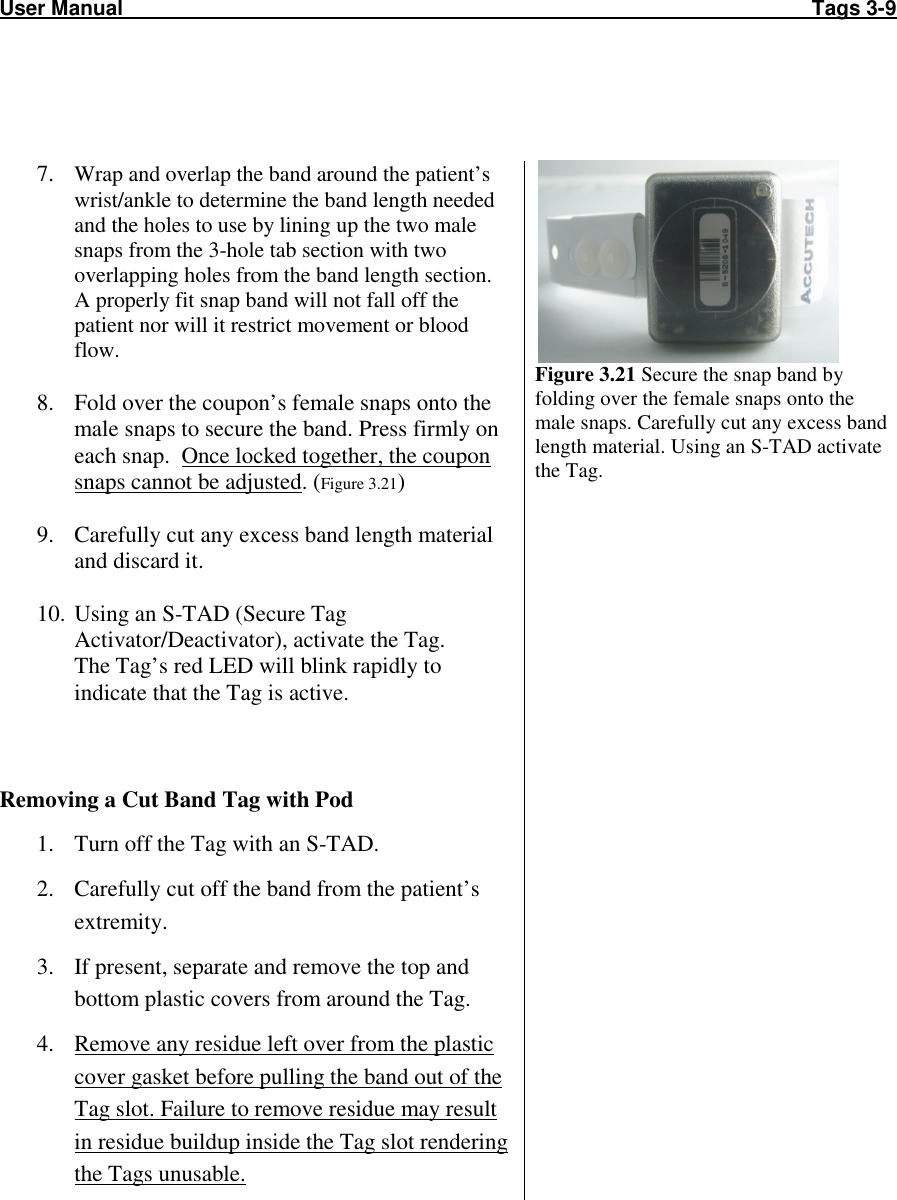
![User Manual The Keypad 5-5 How to set the relay time (Second Relay) Note: The relay time is factory set to 15 seconds by Accutech. To change the relay time: 1. Enter the installer code [1][1][1][1][*] to enter program mode. You will hear two beeps. 2. Enter [5][0] then the desired relay time (1-999 seconds), then the [#] key. You will hear two beeps. 3. Enter [*] to exit program mode and return the Keypad normal operation mode. (enter programming mode) (selects timer for relay 2) (sets timer to 15 seconds) (exits programming mode)](https://usermanual.wiki/Innovative-Control-Systems/HWHY-660017/User-Guide-3930142-Page-55.png)
![5-6 The Keypad User Manual DAP Instructions Note: DAP (Direct Access Programming) should only be used if the Keypad programming has become unstable (that is, if during programming steps you continually receive 5 beeps between steps). DAP programming will reset the KP-103 keypad to Accutech factory settings. 1. Remove power and keypad faceplate from back box. 2. Move DAP jumper from OFF position to ON position. 3. Apply power to keypad. 4. Move DAP jumper back to OFF position. 5. Enter [8][9][0][1][#] to Initialize (2 beeps) 6. Enter [0] (to select User Code 0) 7. Enter [1][1][1][1][#] to designate the new Installer Code (2 beeps) 8. Enter [4][0] then [1][5] (to set to 15 seconds), then [#] (2 beeps) 9. Enter [5][0] then [1][5] (to set to 15 seconds), then [#] (2 beeps) 10. Enter [1], then [0][1] (to select User Code 01), then [1][2][3][4][#] (2 beeps) 11. Enter [2], then [1], then [7][1][3][9][#] (2 beeps) 12. Enter [*] to exit (2 beeps) How to change the installer code Note: The original installer code is 0000. If the installer code is unknown (or differs from the Accutech preprogrammed 1111) and you need to revert back to this code, go to the DAP instructions section. 1. Enter the installer code [1][1][1][1][*] to enter program mode. You will hear two beeps. 2. Enter [0] then the new desired installer code number (4-8 digits) then the [#] key. You will hear two beeps. 3. When finished, enter [*] to exit program mode and return the Keypad normal operation mode. Changing the Installer Code: (enter programming mode) (selects user code 0) (sets 5555 to be the new code) (exits programming mode)](https://usermanual.wiki/Innovative-Control-Systems/HWHY-660017/User-Guide-3930142-Page-56.png)