Innovative Wireless Technologies ASM100001 Miner Mesh Radio User Manual Title of this
Innovative Wireless Technologies, Inc Miner Mesh Radio Title of this
User Manual

L-3 SERVICES
Global Security & Engineering Solutions (GS&ES)
ACCOLADE Wireless Mesh
Mine Communications System
Miner Mesh Radio (MMR)
Operator Manual
Manual 100001 Rev 7
L-3 Services Incorporated
Global Security & Engineering Solutions
Mine Safety Office
9302 Lee Highway • Suite 800
Fairfax, VA 22031
Phone 703.934.7800 • Fax 703.383.5773

- 1 -
TABLE OF CONTENTS
Page
Terms of Use……………………………………………………………………………………. 2
Handset Controls and Features…………………………………………………………………... 4
Handset Operations………………………………………………………………………………10
Other Handset Features and Functions…………………………………………………………..20
Handset Maintenance……………………………………………………………………………26
Radio and Environmental Specifications………………………………………………………...26
Quick Reference Charts………………………………………………………………………….27

Terms of Use
IMPORTANT: Any person using the Handset agrees to abide by the terms of operation and use
given below:
WARNING:
1. The battery pack is to be charged according to the manufacturer’s instructions in fresh air
locations only.
2. The MMR handset is used in locations greater than 5 feet from blasting circuits.
3. The MMR handset is only approved for use with external speaker / microphone Part No.
26832 and Headset Part No. SCD10010.
4. The MMR Handset, external speaker / microphone Part No. 26832 and Headset Part No.
SCD10010 must be built according to drawing number ASM100001.
5. MSHA approved for use with the Part No. 70007, 3.65 V, 4.8 Ah, 5 A Max Lithium Ion
rechargeable battery.
6. The battery shall not be replaced by the user.
7. This device complies with part 15 of the FCC Rules. Operation is subject to the following two
conditions: (1) This device may not cause harmful interference, and (2) this device must
accept any interference received, including interference that may cause undesired operation.
8. This equipment is in compliance for localized specific absorption rate (SAR) for uncontrolled
environmental / general population exposure limits specified in ANSI/IEEE Std. C95.1-1999.
9. Changes or modifications not expressly approved by L-3 Communications could void the
user’s authority to operate the equipment.
10. To comply with RF safety requirements use the specific belt clip. All other belt clips should
be avoided and may not comply with RF safety requirements (for fair-trade do not exclude
3rd party accessories).
11. NOTE: This equipment has been tested and found to comply with the limits for a Class A
digital device, pursuant to part 15 of the FCC Rules. These limits are designed to pro-vide
reasonable protection against harmful interference when the equipment is operated in a
commercial environment. This equipment generates, uses, and can radiate radio frequency
energy and, if not installed and used in accordance with the instruction manual, may cause
harmful interference to radio communications. Operation of this equipment in a residential
area is likely to cause harmful interference in which case the user will be required to correct
the interference at hi own expense.

- 3 -
Proximity to Blasting Components
The transmitted waveform characteristics are short duration (milliseconds/second) pulses, with a
power level of one (1) watt or less. For this reason the energy density is very low such that the
handset is classified as a low Power RF source as defined by the Institute of Makers of
Explosives, Safety Library Publication No. 20. Therefore, the Handset shall not be turned on
or operated within five (5) feet with respect to explosives or blasting components.
- 4 -
Handset Controls and Features
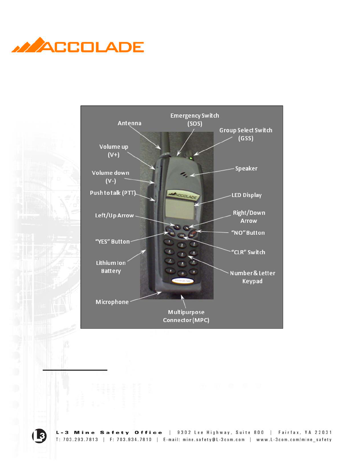
Figure 1 shows the handset and identifies some of the key user controls and features.
Figure 1: Handset and Location of Primary Features and Controls
Handset Controls
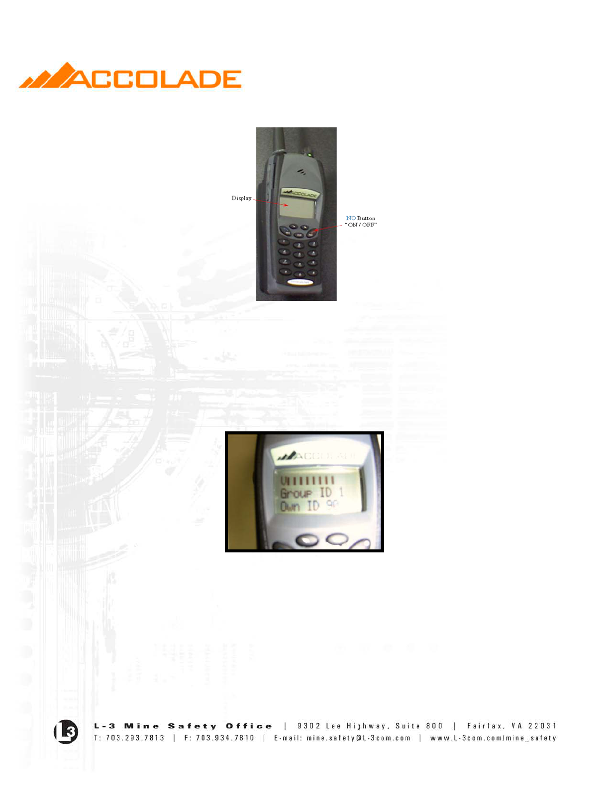
On-Off Switch
• Turns handset on and off.
• If the handset is ON and in Group Mode, holding down the NO button for four (4) seconds
will turn the handset OFF.
- 5 -
• The handset must be in Group Mode in order to turn it OFF.
Fig.2 On/Off Switch
Volume Control Switches (V+/V-)
• Control the volume of received voice at the speaker output.
o V+ increases the volume.
o V- decreases the volume.
• The volume level is indicated by a bar graph on the LCD screen for a few seconds
following adjustment. See Fig 2.
Fig 3 – Volume Control Bars
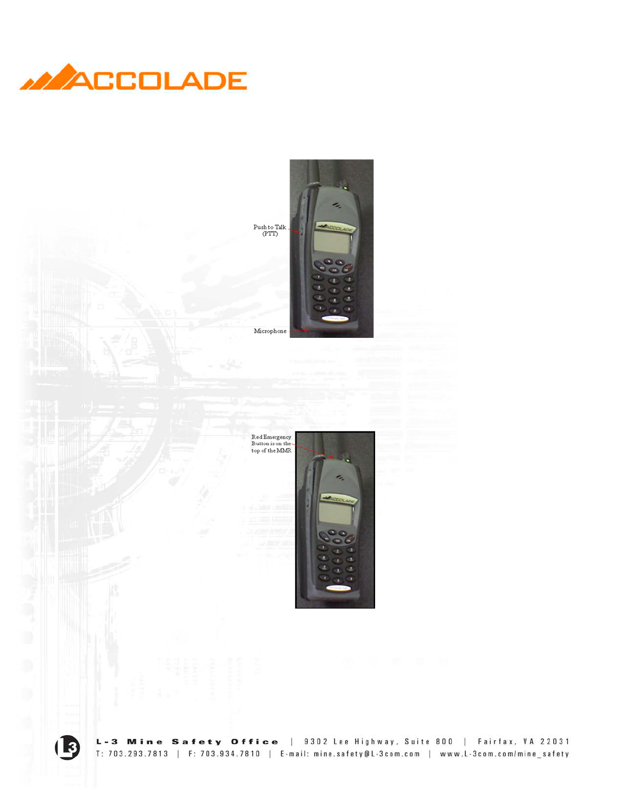
Push-to-Talk Switch
• Used to send voice messages.
• An asterisk symbol (*) will appear next to the Group ID # to indicate the handset is in the
voice transmit mode.
• The speaker is disabled during transmission (except for Emergency information).
• If the PTT button is depressed continuously for more than 2 minutes the Handset will stop
transmissions and sound an audible chirp. The handset will then not transmit again until the
PTT button has been released and then pressed again.
- 6 -
• In Orphan Mode (i.e., when the handset is outside network coverage) the handset will not
attempt to transmit but will sound an audible chirp when PTT is pressed.
Fig. 4 Push-To-Talk and Microphone
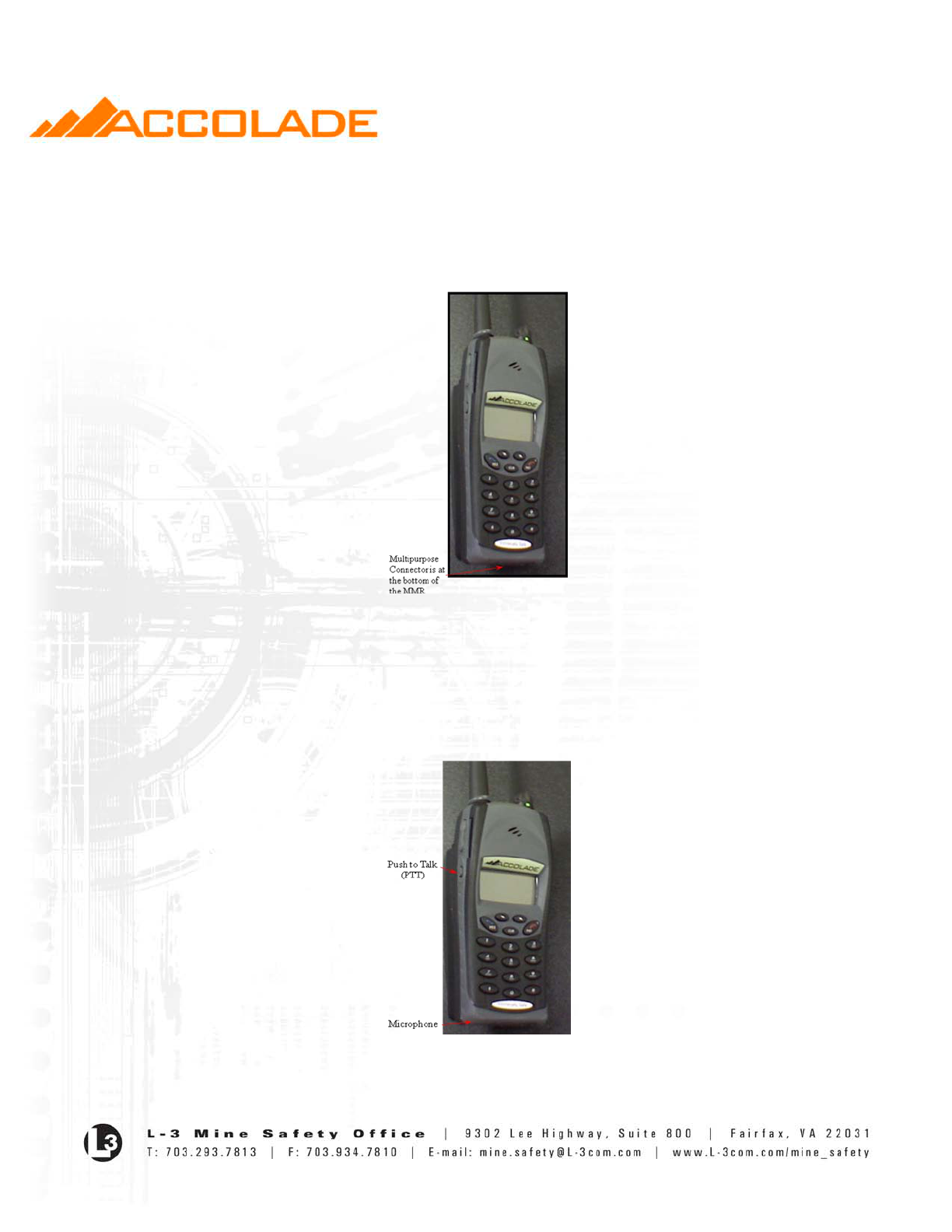
Emergency Switch (SOS)
• When pressed and held down for two (2) seconds the handset enters Emergency Mode.
• Can also be used to clear the Emergency Mode.
Fig.5 Emergency Switch
- 7 -
Multipurpose Connector (MPC)
The MPC provides contacts to:
o Charge battery.
o Update the operational software.
Fig. 6 Multi Purpose Connector (MPC)
Microphone
• Picks up the user’s voice for transmitting voice message
• High levels of background noise may cause voice information to be difficult to discern by the
receiving handsets.
Fig. 7 Push-To-Talk and Microphone
- 8 -
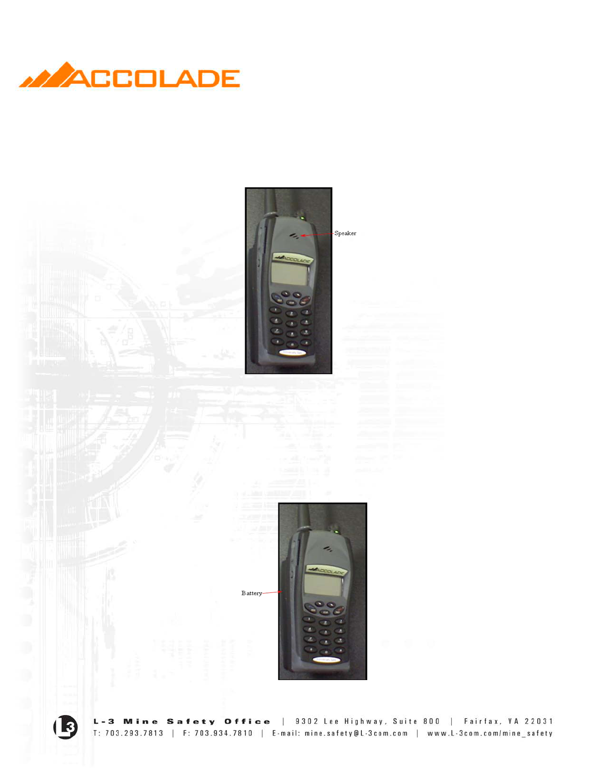
Speaker
• Can be used for private conversations or as a speaker phone.
• Users must exercise care when setting the volume to avoid damage to their ear drum when
using the speaker for private conversations.
Fig.8 Speaker
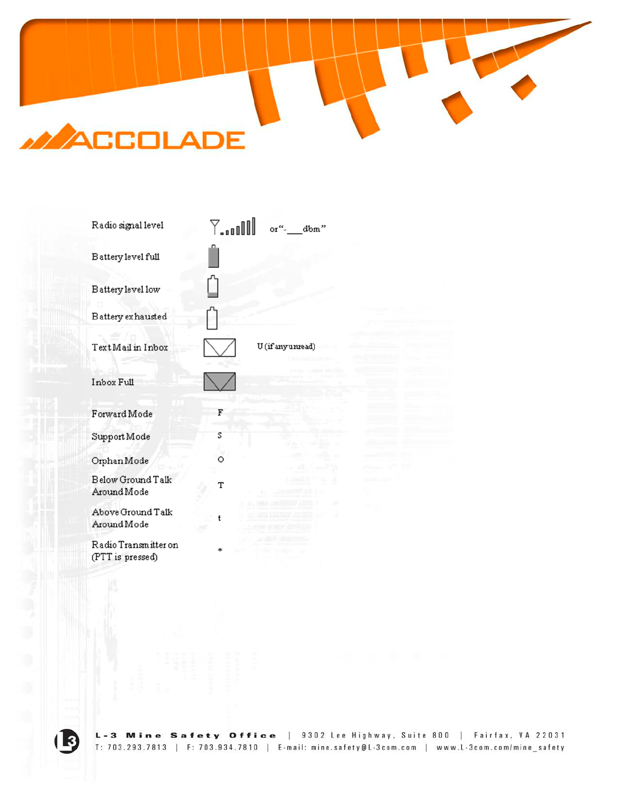
Battery
• Is a Lithium-Ion Prismatic cell that supplies a nominal 3.65 VDC with a capacity of up to 4.8
Ah.
• The battery maximum output voltage may be as high as 4.2 VDC, and may go as low as 3.3
volts due to temperature and discharge.
• The battery pack should not be removed from the handset by the user.
Fig.9 Battery
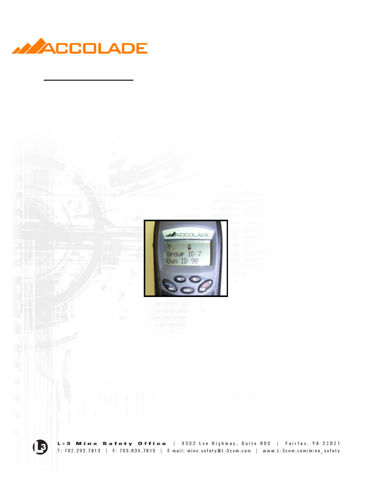
LCD Display Symbol Definitions
- 10 -
Handset Operation
Voice Operation Modes
Group Mode
• Group mode allows the user to send and receive voice data to and from all users set to the
same Group ID (GID).
• Broadcast Group switch position is zero (0). The position is also identified as green on the
GSS.
• The destination address used in the transmission of voice data (Destination address) from
Group Mode is as defined by the Group Selection.
• No priority is given for Broadcast Group data.
• To respond to the Broadcast Group the Handset must be set to Broadcast.
• On power up, the Handset is in Group Mode. The LCD display will be similar that shown
below:
Fig. 10 Group Mode
• The handset returns to Group Mode by pressing and holding the NO button for two or more
seconds except when in Emergency Mode or if the handset is already in Group Mode.
Call Back Mode
• A handset is configured to accept incoming calls from the Broadcast group, the handset’s
current group setting, or to its own individual Identification Number (Node ID).
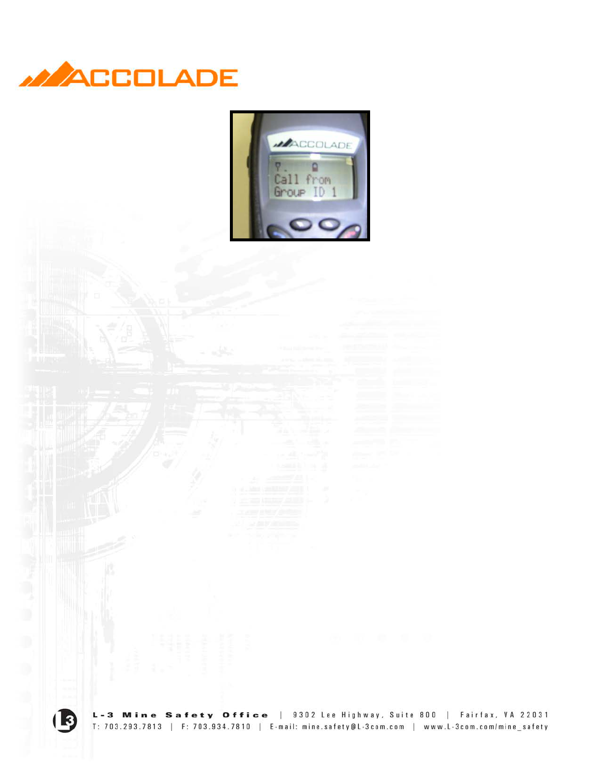
• The handset switches to Call Back Mode whenever voice data is received. The LCD will
display the following:
- 11 -
Fig. 11 Call Back Mode
• The last line represents the Caller’s ID and displays either the Group or Individual ID
depending on the type of call (Group or Individual). The last line on the LCD could be:
o Group ID # or Broadcast for Group ID 0.
o Handset # if receiving an individual call from another handset.
• Once in Call Back Mode, the handset will remain in Call Back Mode until another mode is
overtly chosen by the user (including if the user changes the group setting), or after a period
of prolonged silence is detected for 15 seconds, in which case the Handset returns to Group
Mode. Silence is defined as no voice data received or no detection of PTT.
• After receiving Broadcast voice, the handset immediately returns to Group Mode as soon as
the broadcast event has terminated (originator releases PTT).
• Except for Broadcast reception, the destination address in Call Back Mode is equal to the
address of the originator of the last voice data received. This may be a group address or an
individual address. In the case of Broadcast reception, the Destination address is that set just
prior to receiving the Broadcast message.
Call Mode
• The Handset enters Call Mode from Group Mode or Call Back Mode by entering the
individual Node ID of the desired destination address using numbers 0 through 9 on the
keypad followed by holding the YES button for two (2) seconds.
• There is no need for the user to enter leading zeros or will leading zeros be displayed.
• The “CLR” button clears the last digit entered.
• The LCD displays the Node ID as it is entered until the YES button is depressed.
• If the YES button hasn’t been pushed within 30 seconds the Handset returns to Group Mode.
• The Destination address (destination) is equal to the Node ID entered.
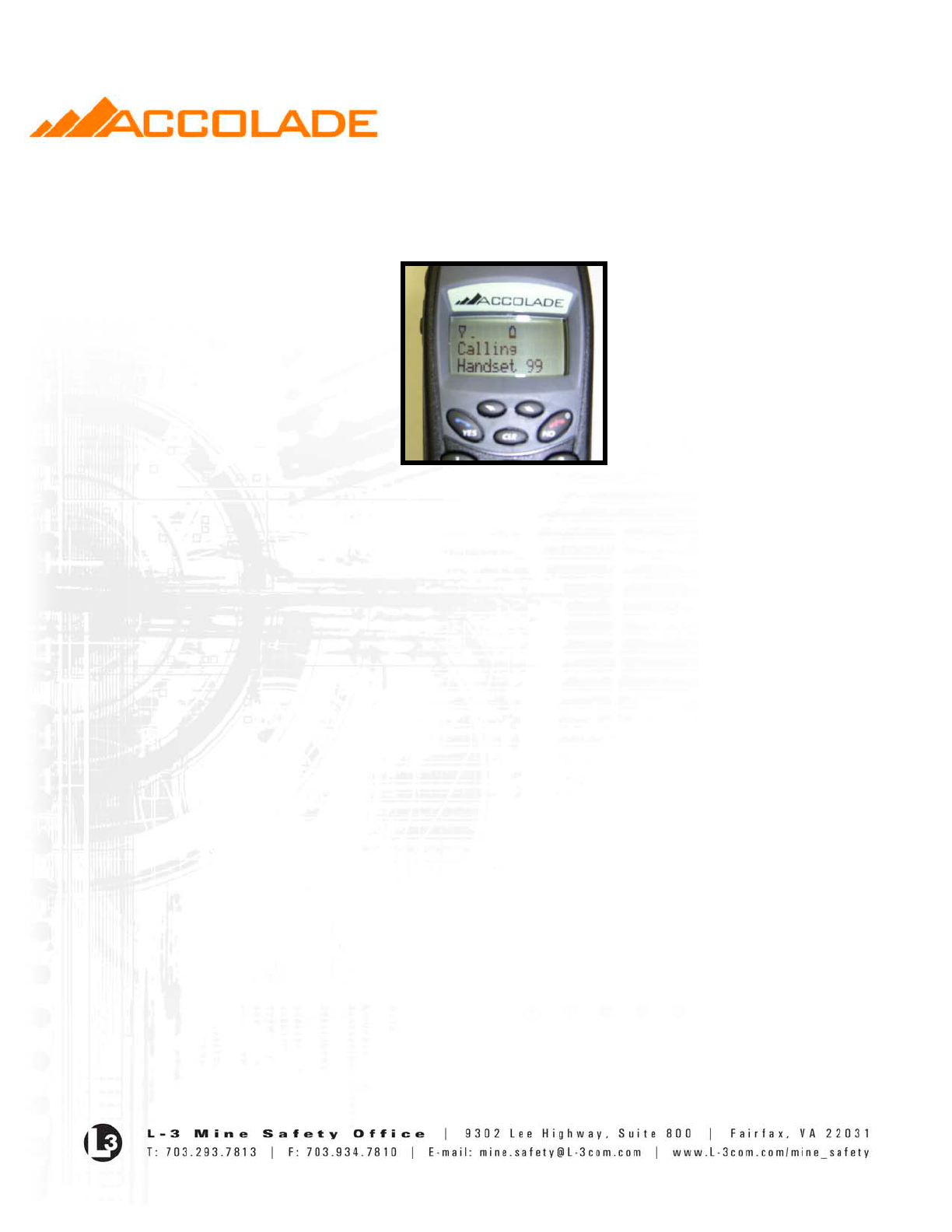
• As digits are entered in Call Mode the LCD displays the following:
Call
Handset NNNN
where NNNN represents the individual handset ID called, such as Handset 99 (see Fig __
below).
- 12 -
• Press YES for two (2) seconds.
• Once YES is pressed for two (2) seconds the Handset displays the following while in call
mode:
Fig. 12 Call Mode
where the last line represents the Individual ID entered.
• If the PTT is pressed before YES has been pressed and held for at least two (2) seconds the
handset will not transmit but will sound an audible chirp to indicate the PTT is not active in
this “in-between” state.
• Once in Call Mode, the Handset will remain in Call Mode until another mode is overtly
chosen by the user. For a person-to-person call to remain active indefinitely, both parties
must initiate a call to each other. The second party must initiate the return call before a 15
second timer expires.
• Except for Emergency (see below), Call Back Mode cannot be entered while in Call Mode.
Hence, unless it is an Emergency message, voice data destined for a Handset that is in Call
Mode is discarded by the Handset. The use can only communicate with the person called.
Emergency Mode
• Emergency Mode is a special Group call that overrides any other Handset mode and
conversation except for All-Call. While in Emergency Mode, the Handset operates as
follows:
o All other voice processing is immediately terminated
o Priority is given over non-emergency group or individual calls:
Emergency calls for the Broadcast Group calls over all other types of incoming
calls
Emergency calls for the Handset’s current Group (established by group selection)
over everything but Emergency Broadcast calls
o Emergency Call indicators are activated as specified herein
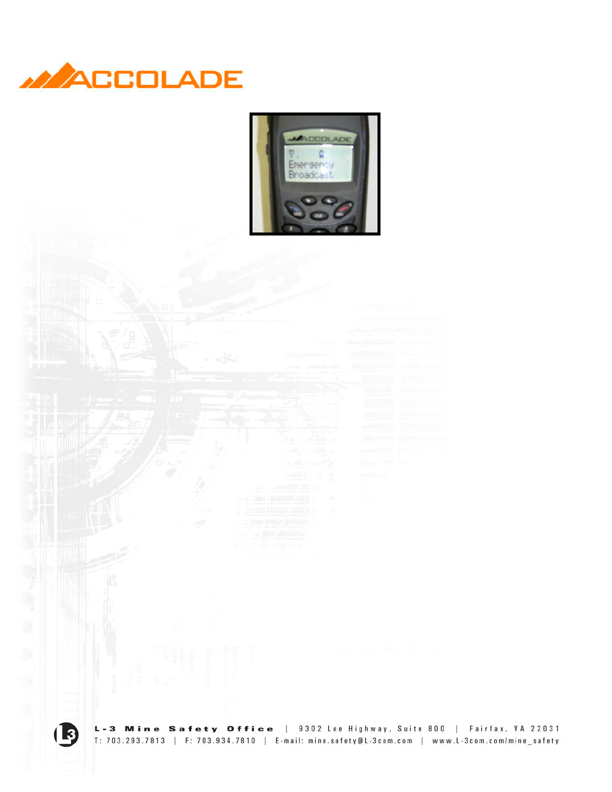
o The LCD displays the following:
- 13 -
Fig. 13 Emergency Mode
where the last line represents the Group Initiating the Emergency. The last line on the LCD
could be Group ID X (or “Broadcast” for Group ID 0).
• The Destination Address is the current group setting or Broadcast Group (whichever initiated
the Emergency communication) with the Emergency bit set for all subsequent transmissions
Entering Emergency Mode
• The Handset enters Emergency Mode by one of two means:
o On receipt of a Group or Broadcast emergency call
o Pressing and holding the Emergency Button for two (2) seconds.
Exiting Emergency Mode
• The Handset remains in Emergency Mode until one of the following conditions is met:
o Nonemergency Voice data is received from the originator of the first emergency
message.
o No emergency data is received from any source for ten (10) continuous minutes
(Emergency Silence Interval – ESI).
o Pressing and holding the Emergency Button for two (2) seconds.
• On exiting Emergency Mode the Handset will:
o Return to the Group Mode as set by the GSS
o Clear the Emergency Bit in all subsequent transmissions.
All-Call Mode
• All-Call Mode is special call type that can only be initiated from the Mine Operations Center
(MOC).
• It allows for the radio system to grant uninterrupted access of all voice channels for the MOC
originated call.
• When this field is set the Handset will operate as follows:
o All other voice processing is immediately terminated
o Priority is given to All-Calls over all other types of incoming calls

- 14 -
o “The LCD displays the following:
Emergency
All Call
• Once in All-Call Mode, the Handset will remain in All-Call Mode until the MOC sends a
voice packet that does not indicate All-Call, or until one second has elapsed without
receiving an All-Call packet.
• The Handset returns to Group Mode on exiting All-Call Mode.
Congestion Indication
• The Handset will indicate congestion for voice calls per Table 2 when the radio channel used
for data transmission is preoccupied by other users.
• The LCD displays “No Channel” on the last line of the LCD for 5 seconds, and then returns
to the previously displayed data.
• There is no congestion indication for text.
• This indication does not apply when in Talk Around or Forward Mode.
Talk Around Mode
• Talk Around Mode is set by the user. This is a “walkie-talkie” mode.
• When in Talk Around Mode the handset is able to talk only to other handsets also in Talk
Around Mode and within radio range of each other.
Entering Talk Around Mode
• The handset is set to Talk Around Mode by pressing the “*” key for 2 seconds when in
Group Mode. The LCD displays:
> Enter
Talk Around?
• If the “YES” button is pressed the handset enters Talk Around Mode.
• Pressing the “NO” button returns the handset to normal Group Mode.
• The handset shall automatically switch between Above and Below Ground Talk Around
Modes. The Above Ground is the default condition and is indicated by a lower case “t” on
the LCD. The Below Ground is indicated by an upper case “T”. The Handset is in Below
Ground Mode only when the Below Ground Mesh infrastructure has been detected.
Exiting Talk Around Mode
• The handset exits Talk Around Mode by pressing the “*” key for 2 seconds when in Group
Mode. The LCD will display:
>Exit
Talk Around?
- 15 -
• Pressing the “YES” button returns the handset to the Group Mode screen with whatever
Network Status is indicated (one of the mesh modes (normal, Orphan, Forwarding or
Support)).
• Pressing the “NO” button returns to the Group Mode screen still in Talk Around.
Text Operation
Text Paging
• The Handset is capable of transmitting and receiving text messages of length up to 48
alphanumeric characters.
• The Handset stores up to ten (10) received text messages. A record of sent text messages is
not stored.
• The Handset receives and stores text messages regardless of the current operating mode.
• When in text mode, if no button is pressed within 30 seconds the handset will return to Group
Mode.
Text Mode
• Text Mode is entered by pressing and holding the CLR button for three (3) or more seconds
from the Group Mode or Call Back Mode.
Fig. 14 Text Mode
• The Handset will continue to receive voice data while in Text Mode. Voice operation is
Group Mode or Call Back Mode, depending on whether responding to in-coming voice.
• All voice mode audible, vibration and LED alerts are still provided while in Text Mode.
• Text messages originating at the MOC may be sent to individuals or groups, including the
broadcast group.
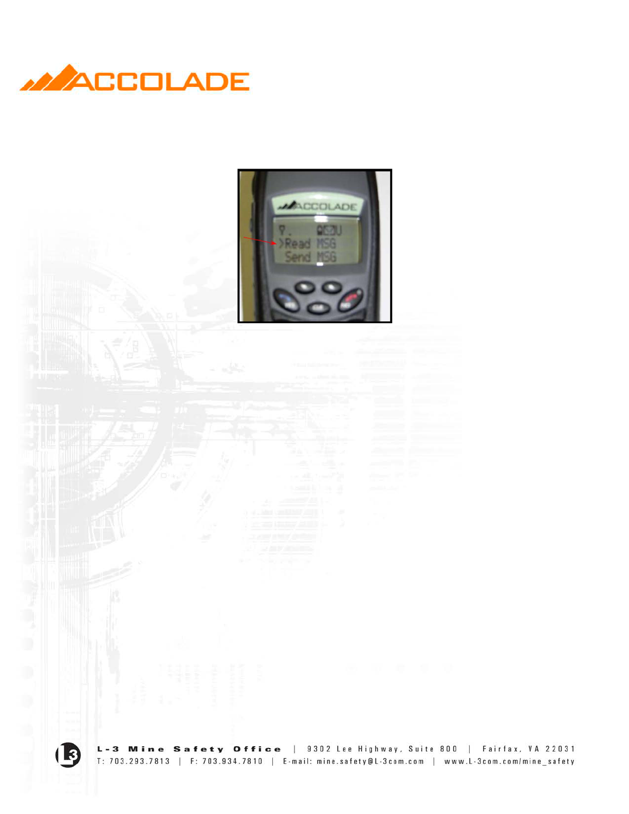
• Once the user enters text mode he is able to scroll through the following options using the
Up/Left and Down/Right buttons in conjunction with the “>”:
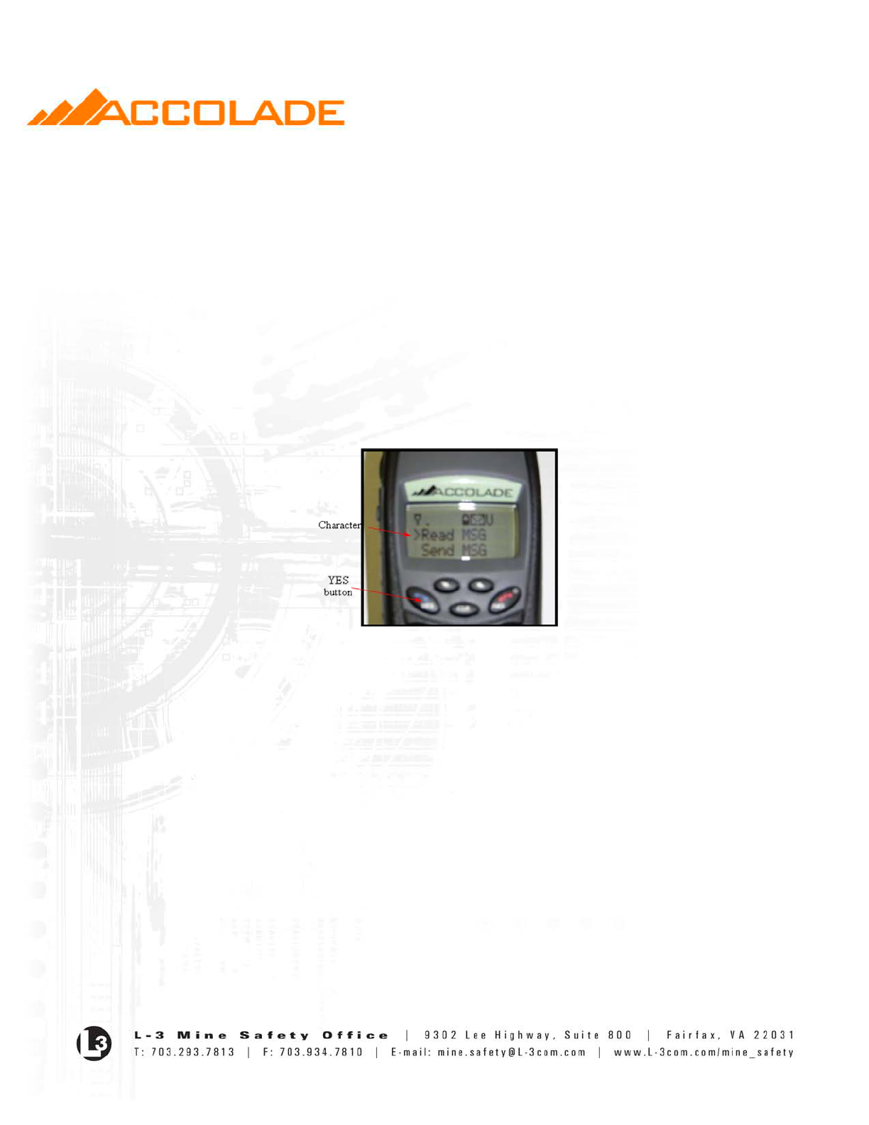
o >Read Msg
- 16 -
o Send Msg
o System Info
o Utilities
Fig. 15 Read Message
Reply Requested Text Mode
• The MOC may elect to request that the destination device respond with a Reply Requested
(RR) Response text message. In such cases, the Handset will automatically respond when
the message is read by the user with an ACK message.
• The Handset cannot initiate a Reply Requested Text message.
Emergency Text Mode
• Emergency Text Mode is entered from text mode by pressing and holding the Emergency
button for three (3) seconds.
• Emergency text messages received at the MOC are immediately replied to with an ACK
message.
• When an ACK message is received, the Handset displays the following:
Emergency Text
XXX Received
where XXX is the message number assigned by the system to the original emergency text
message.
• Once the message is read at the MOC a second message is automatically sent to the
Handset. When a Reply Request Response message is received, the Handset displays the
following:
Emergency Text
XXX Read
where XXX is the message number assigned by the system to the original emergency text
message.
- 17 -
• Similarly, the Handset will automatically respond to text messages from the MOC where the
Emergency bit is set with an ACK message. No ACK messages are sent by a Handset to
another Handset.
• The MOC may request both a Reply Requested Response and an Emergency Response in a
single message (EM set and RR set). In such cases, both responses are returned by the
Handset when the following conditions are met:
o The Emergency Response is sent on receipt of the message,
o The Reply Response is sent when the message is read on the Handset. Both
responses are sent automatically.
Navigation in Text Mode
• Options are selected by using the Up/Down arrows in conjunction with the “>” character (the
“>” is the first character on the line to be selected) and pressing YES.
Fig. 16 Text Mode Navigation
• The NO button is used to return to the previous screen menu.
Sending Text Messages
• Messages are sent from the Handset by entering Text Mode and then selecting “Send
Message”.
• When “Send” is selected, the LCD displays the following:
Send Text:
>Group ID X
Individual
• If Group ID X is selected (where “X” represents the group setting) by pressing the “YES”
button the Text message is sent to the Group ID associated with the current group setting and
the Message is displayed. If the group is set to 0, the second line will say “Broadcast”.
• If “Individual” is selected by pressing the “YES” button, the LCD shall display the
following:
Send Text to
Handset XXXX
- 18 -
where XXXX represents the Individual ID to be entered.
• A “___” will initially be shown to indicate to the user an entry is expected. For example,
Handset 225 would be displayed if 225 was entered followed by the “YES” button.
• Handsets cannot request a “Reply Request” for an individual or Group in normal Text or
Emergency Text modes.
• To send a text message solely to the MOC the user must enter the MOC’s four digit Node ID
(0009 or just 9 (lead in zeros are not required)).
• The “Send Message” option is disabled when in Orphan or Talk Around Modes.
Creating Text Messages
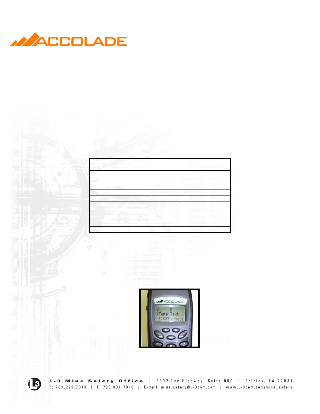
• The Handset is capable of sending free-form typed text or one of ten predefined “canned”
text messages as given in Table 1 below:
Message
No.
Message Text
1
Affirmative
2
Negative
3
OK
4
Medical Emergency
5
Trapped Send Help
6
Roof Fall My Location
7
Transport Needed
8
Mechanic Needed
9
Electrician Needed
10
Foreman Needed
Table 1: Predefined Text Messages
• Once the destination for the text message is selected the LCD displays the following:
>Type Text
• A “space” (for the “>” followed by the “short cut number” then the first canned message,
a “space” followed by the “short cut number” second canned message and so on.
Fig. 17 Text Message Generation

- 19 -
• Messages are scrolled through and selected using the Up/Left, Down/Right button in
conjunction with the “>” and pressing YES. If a message extends beyond 11 characters it will
continue on the next line.
• If a number button is pressed the screen will display the canned message associated with that
number. The “0” button will short cut to the tenth canned message.
Typed Text
• If the “Type Text” is selected the LCD will be blanked with a curser comprised of “__”
appearing on the left most character on the top line of the LCD.
• Messages up to 48 characters can be entered (Upper and lowercase A through Z, space, 0
through 9 and a subset of the special characters supported by the LCD).
• A User then enters alphanumeric characters by pressing the “2” through “9” buttons. If the
same number is push within 1 second the display will change to the next letter associated
with that button.
Examples:
o For the “2” button, the display would go from A B C 2 A B …
o For the “7” button the display would go from P Q R S 7 P Q …
*Note the “7” button and “9” button have 4 letters associated with them
• After a character has been entered (the 1 second timer expiring) the cursor “__” will appear
to the right of that character.
• If a different button is pressed first it’s associated letter is displayed to the right of the last
character.
• When the 36th character is entered the display will scroll up and the first twelve characters
will no longer be displayed. Characters 13 through 24 are on the top line of the LCD and
characters 25 through 36 are on the second line of the LCD. Characters 37 through 48 will
then be entered on the last line of the LCD.
• The “#” button is used to generate blank space character on the LCD.
• The Up/Left button backspaces through the message. The cursor will “flash” on and off to
denote where the next character entered is placed.
• The Down/Right button moves forward through the message.
• The “CLR” button backspaces and clears character just to the left of the cursor.
• The “*” button toggles between Uppercase and Lowercase letters.
• The “1” button rotates through “special characters” (!?.#$&*)
• If the “NO” button is pressed the handset will display “Text Canceled” for five seconds and
then return to Text Mode and the message will not be sent.
• Once a confirmed text message is sent, the Handset displays the following for five (5)
seconds and then returns to Text Mode:
Text Sent
Message# XXX
where XXX is a unique message number assigned to the text message by the system.

- 20 -
• Text Messages are viewed by entering Text Mode and then selecting “Read Message”.
• Messages are displayed in last-in-first-out order, labeled as “>Mnn IDXXXX Y”, where nn is
the number of the message (1 to 10), XXXX is the Source ID of the message originator. Y is
a “U” for unread normal messages, an “E” for unread Emergency messages, or blank for read
messages (either normal or emergency).
• The last message received is always Message one (M1), and each subsequent message in
numbered in order up to the maximum.
• Messages are selected by highlighting the desired message and pressing YES.
• The message may be up to two screens (four lines) in length. Use the Up/Down arrows to
scroll through the message.
• Emergency Response messages are stored and displayed in the form: “ER ACK XXX”,
where XXXX is the messaged number assigned to the original message. Similarly, Reply
Requested Response messages are stored and displayed in the form: RR ACK XXXX.
Erasing Text Message
• Messages are erased by pressing and holding CLR while part of the message is visible on the
screen.
• The user is prompted to verify that they wish to erase the message by displaying the message
“Erase Mn?”
• The message is erased if the user depresses YES, and it is retained if the user depresses NO.
• The display returns to the previous message view screen if the user selects NO in response to
the “Erase Mn?” question.
• “Mn Erased” is displayed for three (3) seconds if the user selects YES in response to the
“Erase Mn” question.
• The display returns to the “Read M1” screen.
• Messages are renumbered after the deletion of a message as described above in last-in-first-
out fashion.
Other Handset Features & Functions
System Info
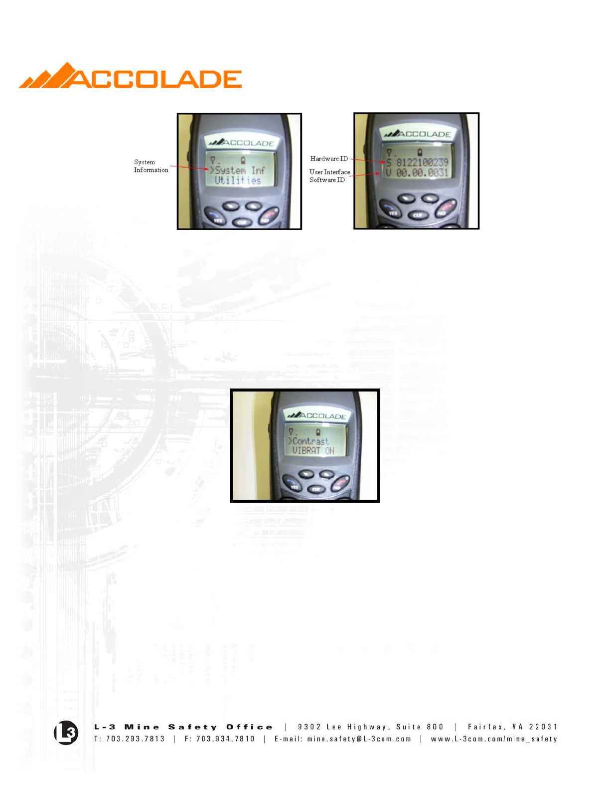
• If “System Info” is selected after entering Text Mode the Handset allows the user to scroll
through the following:
o HW S/N Audio S/N
o Radio Software S/N
- 21 -
Fig. 18 System Information
Utilities
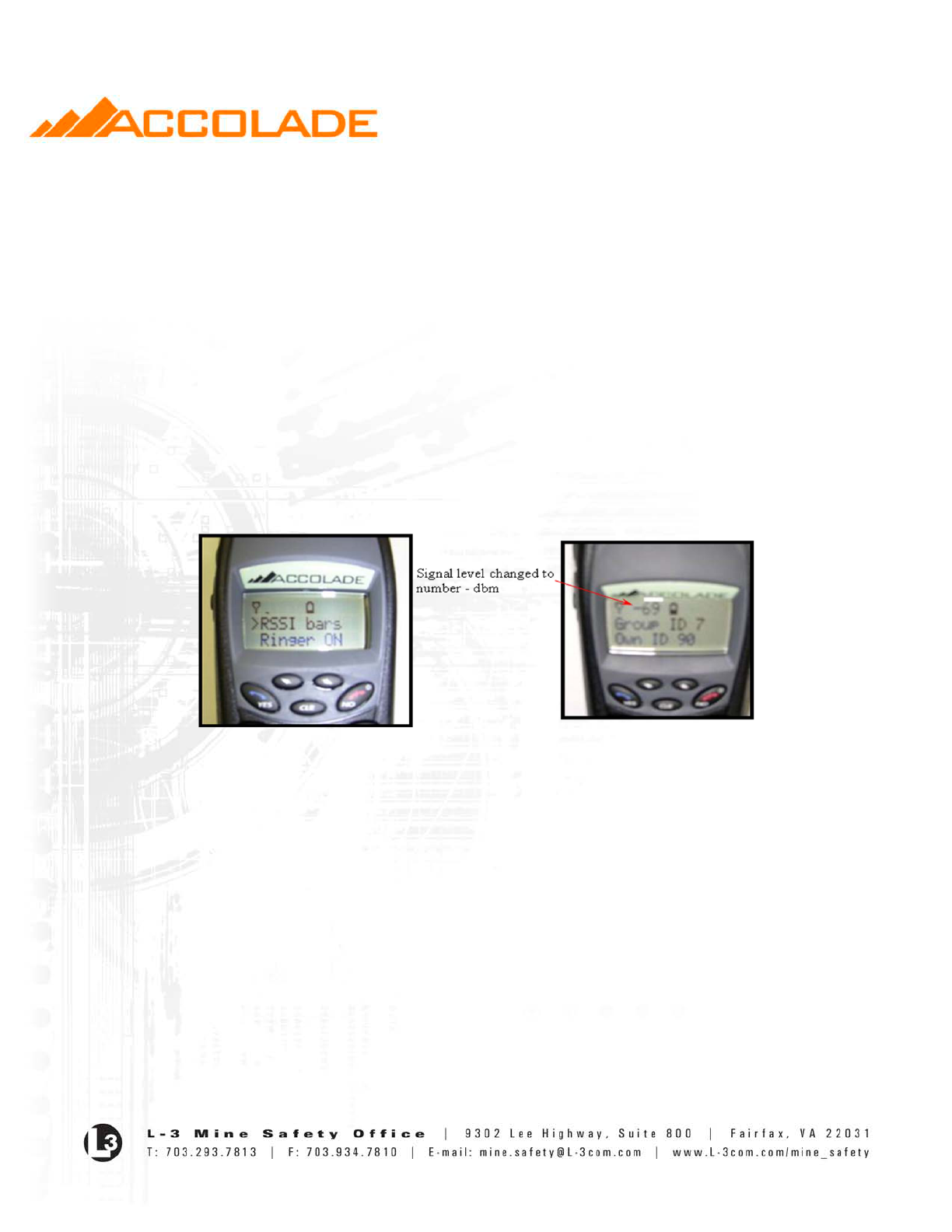
• If “Utilities” is selected after entering Text Mode the Handset allows the user to scroll
through the following on the LCD display:
>Contrast
Vibrator XXX
R SSI - YYYY
Ringer – ZZZ
CLR Mailbox
Fig. 19 Utilities Menu
• Pressing the YES button will select the option. Pressing the NO button will return the user to
the previous screen.
• Contrast: Selecting the “Contrast” option causes the LCD screen to display the following:
Contrast ADJ
#
• The “#” (1 through 4) represents the contrast level. Pressing the Up/Left arrow button
increases contrast on the LCD display. Pressing the Down/Right arrow button decreases the
contrast.
• Pressing the YES button locks in the current contrast and returns the user to the Utility
options screen.
- 22 -
• Pressing the NO button returns the user to the Utility options screen without changing the
contrast.
• For the “Vibrator” option, pressing the YES button causes the LCD screen to display the
following:
>Vibrator ON
Vibrator OFF
• When Vibrator OFF is selected the handset only vibrates for Emergency and ALL-Call
indications.
• For the “RSSI” Option, pressing the YES button causes the LCD screen to display the
following:
>RSSI – bars
RSSI – dBm
• When RSSI – dBm is selected the bars for signal strength indication on the LCD screen are
replaced with the signal level in decibel milliwatts (dbm). NOTE: The larger the negative
numbers the LOWER the signal level.
Fig. 20 RSSI Indicators
• For the “Ringer” Option, pressing the YES button causes the LCD screen to display the
following:
>Ringer ON
Ringer OFF
• When Ringer OFF is selected the handset shall only produce audio tones for Emergency and
ALL-Call indications.
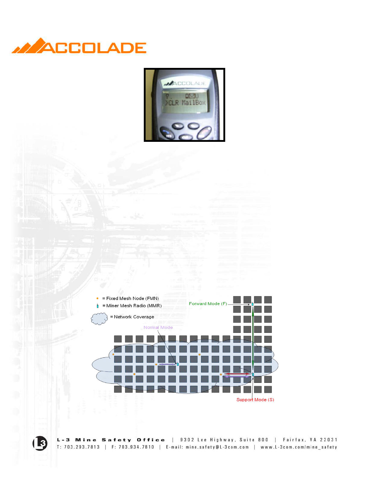
• If the “CLR Mailbox” is selected the handset shall display:
- 23 -
Fig. 21 Clear Mailbox
• If YES is selected all stored text message are cleared. The indicators for any Unread
Emergency Text Messages are also cleared.
Current Network Status
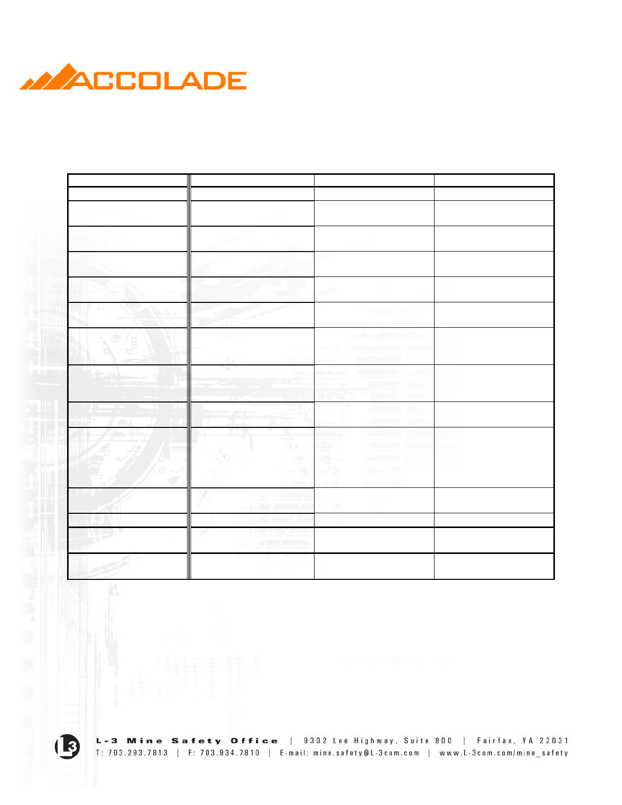
• The Handset monitors the mesh radio network to obtain the current network status of the
Handset to determine if the Handset is operating in the following modes:
o Outside the fixed mesh network (Orphan). Indicators for Orphan Mode are defined in
Table 2.
o Foster Parenting another handset who is outside the fixed mesh network (Support Mode)
o Foster Child operation to the fixed mesh network through another handset (Forward
Mode)
o Low or high power Talk Around Modes (“t”, “T”).
• In All-Call mode, the Orphan indication replaces the audible beeps generated for All-Call
Mode so the miner knows he has left the fixed mesh.
Fig. 22 Network Status Modes

- 24 -
Battery Level Indicator
• The Handset continually monitors the battery condition and displays the battery level as a bar
graph inside a battery divided into five (5) bars. Representing the following:
1) Five lines (completely dark) = >85% battery life
2) Four lines = Between 65% and 85%battery life
3) Three lines = Between 45% and 65% battery live
4) Two lines = Between 25% and 45% battery life
5) One line = between 5% and 25% battery life
6) No lines (just the battery outline) = < 5% battery life
• Battery condition is also reported to the Mining Operation Center (MOC) once every five (5)
minutes.
• The Handset indicates with an audible beep when the battery is less than ten percent of
capacity.
Received Signal Strength Indicator (RSSI)
• The Handset performs periodic polls of the mesh radio network to obtain the RSSI of the
nearest Fixed Mesh Node (FMN).
• The RSSI level is displayed on the LCD as a bar graph or as a negative # followed by dBm(-
__dBm). The higher the negative # the LOWER the signal.
Backlighting
• The Handset has backlighting for the keypad and LCD displays.
• The keypad and LCD display illuminate whenever any button, except the PTT button, is
pressed. Under such conditions, they stay lit for ten (10) seconds after the last key entry and
then automatically extinguish.
• The LCD display automatically illuminates on a change to the position of the GSS. Under
such condition, the LCD stays illuminated for five (5) seconds and then automatically
extinguishes.
Call Indicators
• The Handset indicates the arrival of data at the beginning of an event by one or more of the
following:
o Audible Alert
o Flash of the Top LED
o Momentary Vibration
- 25 -
• Unique and distinctly different audible and LED flash patterns are used to denote the various
call types to the user. Table 2 shows the default settings used for the various call types and
events.
Call Type Audible Alert Pattern Top LED Pattern* Vibrator
Group voice call arrival
None
200 ms flash
None
Broadcast Group voice
call arrival
None
200 ms flash
None
Individual voice call
arrival
400 ms beep
200 ms flash
None
Emergency Group voice
call
Three 200 ms beeps, 100
ms apart
Continuous 200 ms flash,
2 seconds apart
400 ms
All-Call voice
Three 200 ms beeps, 100
ms apart
Continuous 200 ms flash,
2 seconds apart
400 ms
Standard text message
arrival
Two 1 second beeps, 1
second apart
2 second flash
400 ms
Emergency text message
arrival
Five 200 ms beeps, 100 ms
seconds apart
Continuous 2 second
flash, 30 seconds apart
until the message is read
Continuous 400 ms on
pulses, 30 seconds apart
until message is read
Reply Requested
Response text message
received
Two 1 second beeps, 1
second apart
2 second flash
400 ms
Emergency Response text
message Acknowledged
Two 1 second beeps, 1
second apart
2 second flash
400 ms
Channel Not Available
”Busy-like” tone for two
seconds. Volume should be
less than other notification
tones since caller is likely
to have phone by ear.
None
None
No Network Connectivity
(Orphan)
Two, 200ms beeps, every 4
minutes.
None
None
Forward Mode
None
None
None
Support Mode (Foster
Parenting)
None
None
None
Low Battery Indication
One 200 ms beep every 2
minutes
None
None
* For the Top LED the priority for overlapping indicators is: All-Call then Emergency Voice, then Emergency Text.
Table 2: Call Reception Indicators

- 26 -
Handset Maintenance
• Battery should be replaced every 3 years. WARNING!!! Only qualified technicians can
replace the battery on the MMR.
• Any handset that will be kept in storage should be charged to 50% capacity, checked once a
quarter and charge as needed. Handset should be charged to full capacity prior to use.
Radio Specifications
Operating Frequency - 902 to 928 MHz, Pulse Coded
Transmit Output Power Level - 1 Watt Maximum with AGC function
Battery Life (5/5/90) - 28 Hours
Environmental Specifications
Operating Temperature - 20oC to +40oC
Storage Temperature - 40oC to +80oC.
Impact Resistance - Free-fall drops onto a concrete surface from a height of four (4) feet
regardless of Handset orientation at impact.
Humidity - Zero (0) and 100 percent.
Ingress Protection - Water and dust proof to levels specified for IP54 enclosures.
- 27 -
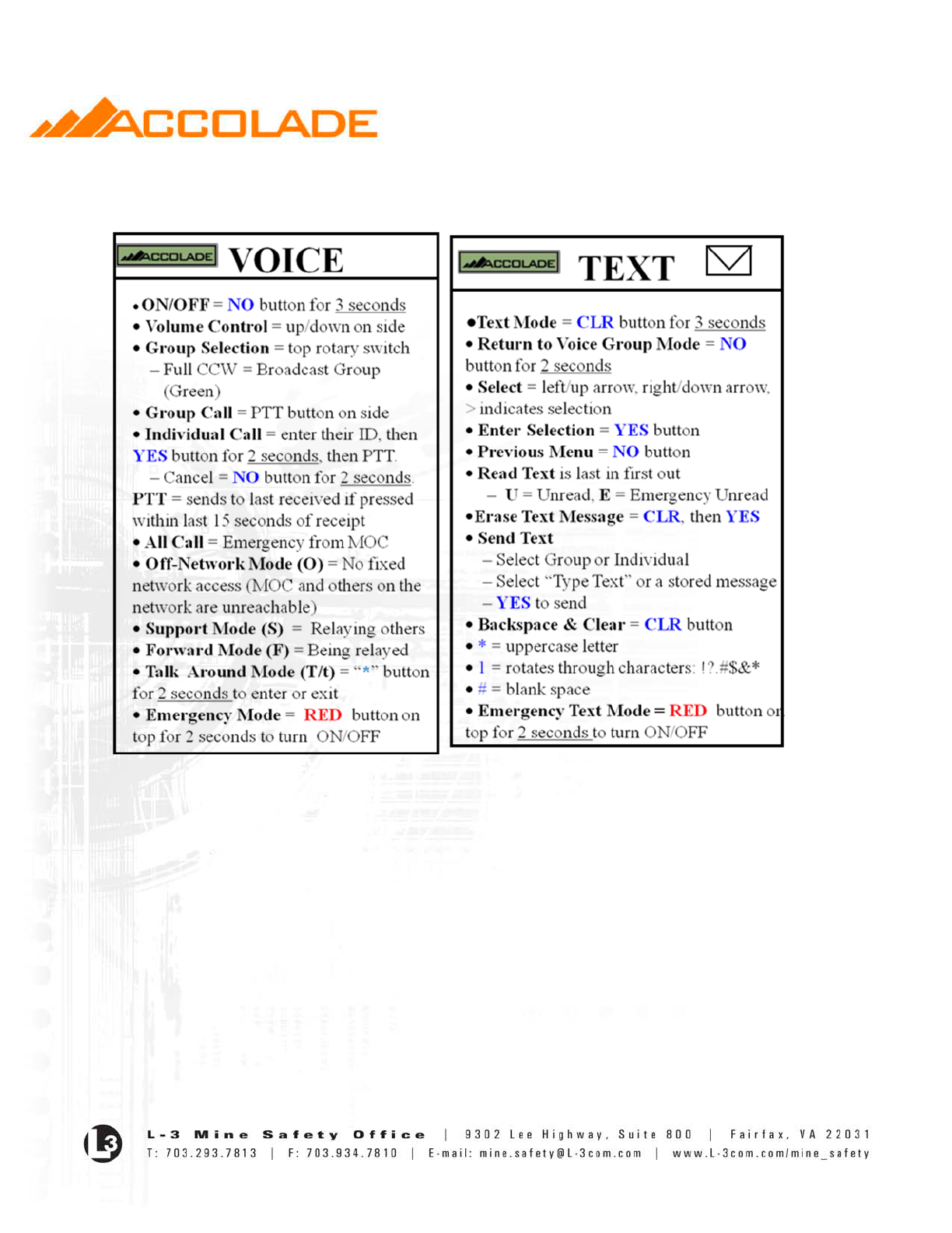
Quick Reference Charts