Innovative Wireless Technologies FAP4100-010 Radio and sensor used to detect intrusion into areas of interest User Manual CERTIFICATE OF COMPLIANCE
Innovative Wireless Technologies, Inc. Radio and sensor used to detect intrusion into areas of interest CERTIFICATE OF COMPLIANCE
User Manual

Rhein Tech Laboratories, Inc. Client: IWT
360 Herndon Parkway Model #: FAP4100-010
Suite 1400 Standards: FCC 15.247/RSS-210
Herndon, VA 20170 FCC ID: SP8-FAP4100-010
http://www.rheintech.com Report #: 2012044
Page 44 of 48
Appendix L: Manual
Please refer to the following pages.
FOR OFFICIAL USE ONLY 1
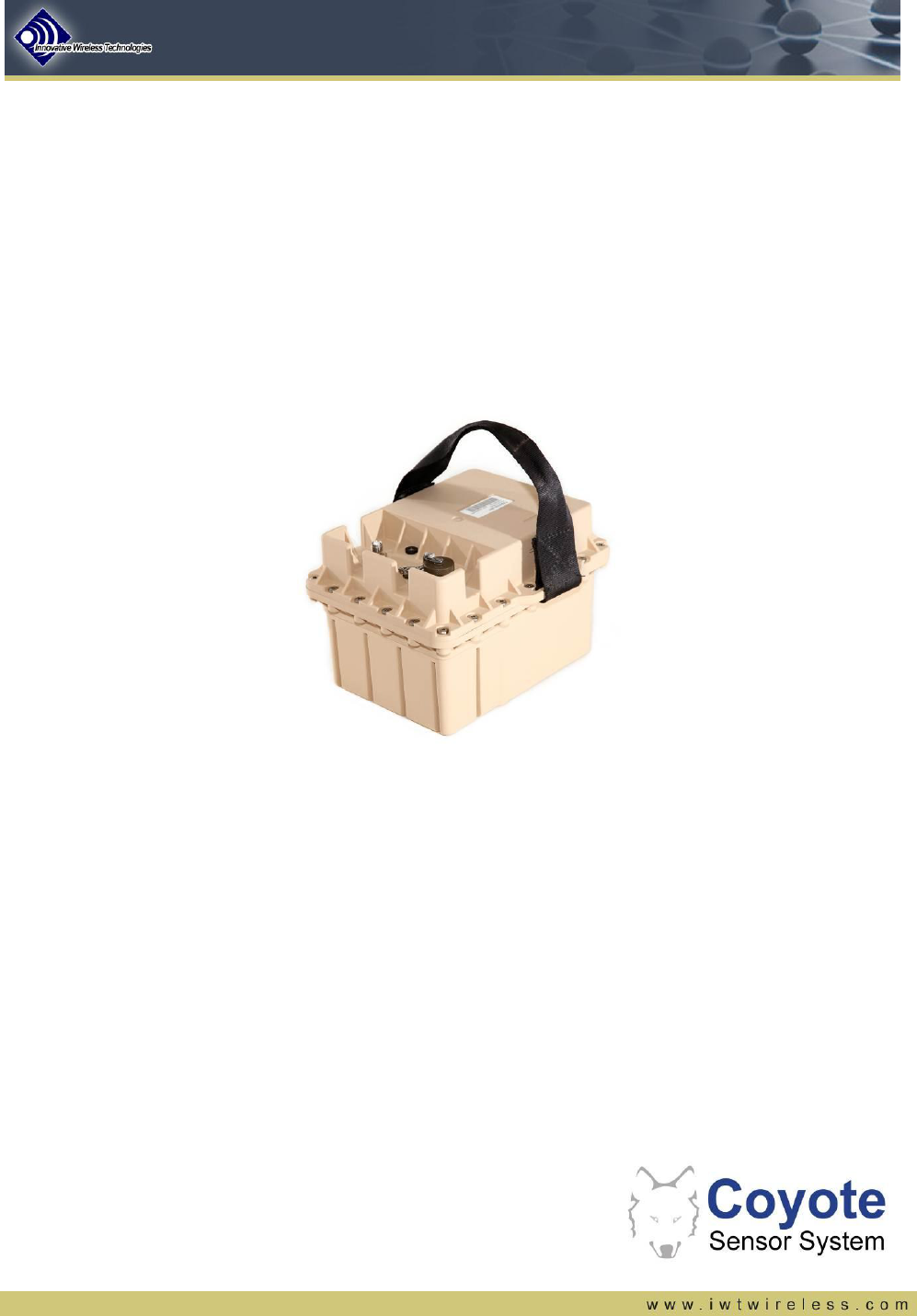
Coyote UGS: User & Installation Guide
Prepared by:
Innovative Wireless Technologies, Inc.
Forest, Virginia
Document # 7720-08-0300 Rev E

FOR OFFICIAL USE ONLY 2
Table of Contents
1. SCOPE ............................................................................................................................. 3
2. UNPACKING AND BATTERY INSTALLATION .............................................................. 4
2.1. Unpacking Coyote UGS Node and Accessories ................................................................................... 4
2.2. Installing Batteries ................................................................................................................................... 4
3. ACTIVATION PROCEDURE ............................................................................................ 6
3.1. Activation Steps ....................................................................................................................................... 6
3.2. LED Status Indicator ................................................................................................................................ 7
4. DEACTIVATION PROCEDURE ....................................................................................... 8
4.1. Deactivation Steps ................................................................................................................................... 8
4.2. LED Status Indicator ................................................................................................................................ 9
5. EMPLACEMENT PROCEDURE .................................................................................... 10
5.1. Connecting Sensor Accessories and RF Antenna ............................................................................. 10
5.2. Digging the Hole and Emplacing the Coyote UGS Node ................................................................... 11
5.3. Bury and Camouflage the Coyote UGS Node...................................................................................... 11
6. EXTRACTION PROCEDURE ........................................................................................ 12
7. SAFETY INFORMATION ............................................................................................... 13
7.1. FCC Notice .............................................................................................................................................. 13
7.2. Industry Canada (IC) Notice .................................................................................................................. 13
8. REVISION HISTORY ..................................................................................................... 13
FOR OFFICIAL USE ONLY 3
1. Scope
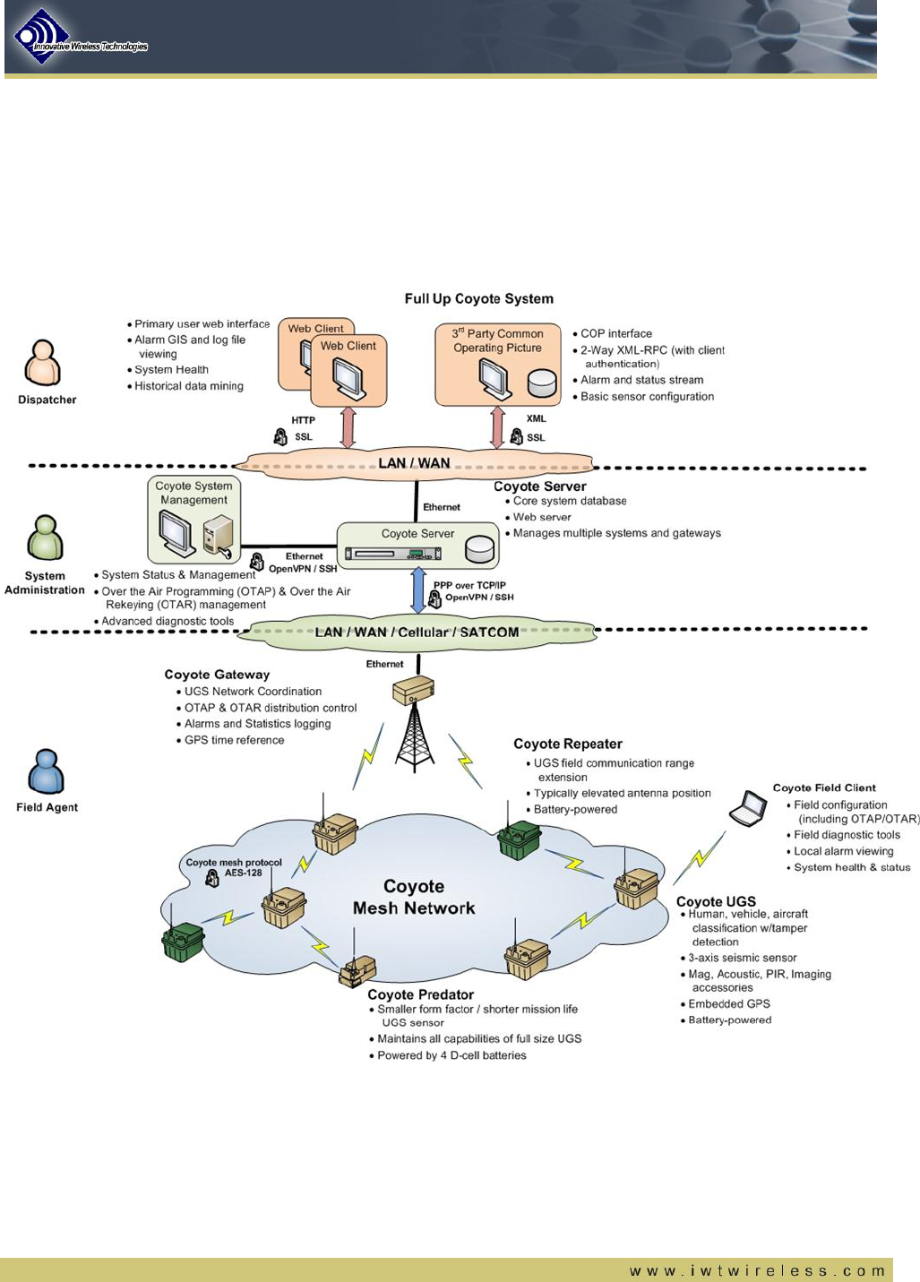
This installation guide provides step-by-step descriptions for field emplacement of the Coyote UGS nodes. The
Coyote UGS node is a multi-modality (seismic, magnetic, passive infrared) unattended ground sensor and is the
core component of the Coyote Sensor System as shown in Figure 1. Individual installation guides provide
instruction for the gateway and server equipment. Operational use of the sensor is found in the Coyote Sensor
System User’s Guide.
Figure 1 - Operational Coyote System Deployment
FOR OFFICIAL USE ONLY 4
2. Unpacking and Battery Installation
2.1. Unpacking Coyote UGS Node and Accessories
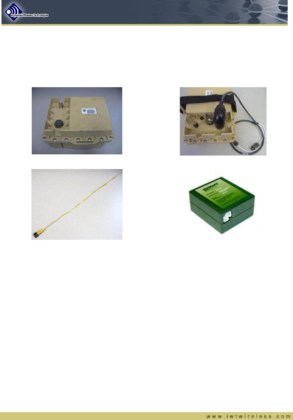
Open the shipping box and unpack its contents: Coyote UGS Node, Antenna, Umbilical Cord, and Batteries (if
purchased). See Figure 2.
CoyoteUGS Node: FAP4100-001
Umbilical Cable: RCL4200-010
Antenna: RAT1000-006
Battery: FAA9000-539
Figure 2 – Coyote UGS components
2.2. Installing Batteries
Note: Be sure to review the battery use instructions and warning labels on the battery and inside the enclosure
prior to installing batteries
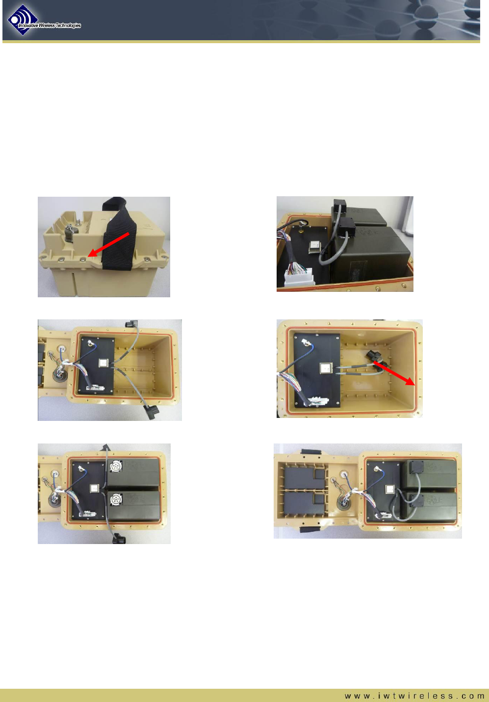
a) To install batteries, remove all screws from around the edge of the Coyote UGS node and open the lid,
taking care not to damage any of the wires between the lid and the electronics compartment.
b) Insert the battery packs (1 or 2 batteries may be installed), as shown in Figure 3.
c) Connect one battery cable to the top of each battery.
d) Check the power on blinking sequence of the LED indicator. Upon power up the LED should cycle
through all three colors (red, green, yellow) and then blink red while the unit performs a self-test.
o If the unit fails self test the LED will change to solid red.
o If the unit passes self-test, that the LED will turn either solid yellow or solid green depending on
the radio activation status.
o A solid yellow indicates that the device is active but radio disabled until the next activation
procedure.
FOR OFFICIAL USE ONLY 5
o A solid green indicates that the device is active and the radio is enabled and will actively seek a
mesh network (higher power drain condition).
e) Verify the environmental seal track is free of dirt and debris. If necessary, use compressed air to clean
out the track.
f) Insert the environmental seal in the seal track or re-insert it as necessary if it has popped out of the
track at any point.
g) Arrange the cables such that they do not impede lid closure.
h) Screw the lid back on (NOTE: The recommended rotational torque on the outside lid screws is 20-
25 in-lbs.)
Screws (a)
Batteries Connected (c)
Open & Empty
Environmental Seal Installed (e)
Batteries Inserted (b)
Batteries Installed
Figure 3: Battery installation process
FOR OFFICIAL USE ONLY 6
3. Activation Procedure
The Coyote UGS node is now ready for activation. The activation procedure should be performed in the field at
the physical location of the placed sensor node. Once the node has been activated, it will begin actively
searching for a GPS lock and record this position as its buried location.
3.1. Activation Steps
The activation steps require no additional equipment or tooling.
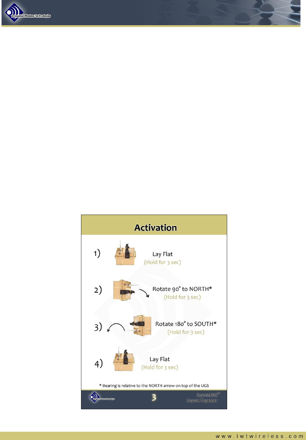
1) The first step is to hold the Coyote UGS node flat and hold this position for 3 seconds.
2) The second step is to rotate the Coyote UGS node 90 degrees to the NORTH* and hold this position for
3 seconds.
3) The third step is to rotate the Coyote UGS node 180 degrees to the SOUTH and hold this position for 3
seconds.
4) The last step is to return the Coyote UGS node to a flat position and hold this for 3 seconds.
* Note – The NORTH bearing is relative to the “N” arrow on top of Coyote UGS housing
The Coyote Activation Field Guide lists these steps and is accompanied by images of the Coyote UGS nodes
for ease of use in the field. This can be seen in Figure 4.
Figure 4 – Coyote UGS Activation Field Guide
FOR OFFICIAL USE ONLY 7
3.2. LED Status Indicator
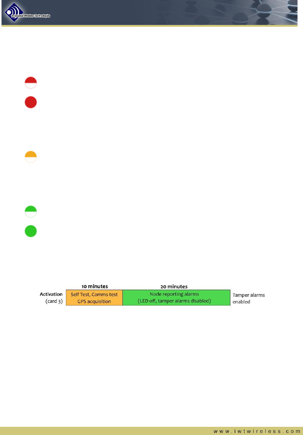
When the activation process has been successfully completed, the tri-color LED on top of the Coyote UGS node
will start blinking RED. This confirms that the node has been activated and is beginning a self-test. If the self-
test fails, the LED will turn solid RED. If this occurs, the Coyote UGS node will need to be deactivated by
following the Deactivation procedure.
RED Blinking – Confirms successful activation and indicates self-test is in progress
RED Solid – Indicates the self-test failed. The LED will remain on until the node is deactivated
If the self-test passes, the LED will begin blinking ORANGE. During this time, it will begin searching for a GPS
lock and checking for communication with the Coyote network. The node may be buried at this time, but it is
advised to wait until a GPS lock and RF communication has been.
ORANGE Blinking – Indicates self-test has passed; node is searching for comms and GPS
Once the node has passed self-test and has established RF communications, the LED will begin blinking
GREEN. Once the node passes self-test, establishes RF communications, and obtains a GPS lock, the LED
will remain solid GREEN. At this time the node it is recommended to bury the Coyote UGS node.
GREEN Blinking – Indicates self-test has passed and the node has established RF comms
GREEN Solid – This confirms successful self-test, RF communication, and GPS lock
The nodes will attempt the self-test process and search for RF communication and GPS lock for a total of 10
minutes once the node has been activated. After 10 minutes from activation, the LED will go off and the node
will begin reporting alarms. After 30 minutes from activation, the node will begin reporting tamper alarms.
Figure 5 - Activation Timeline
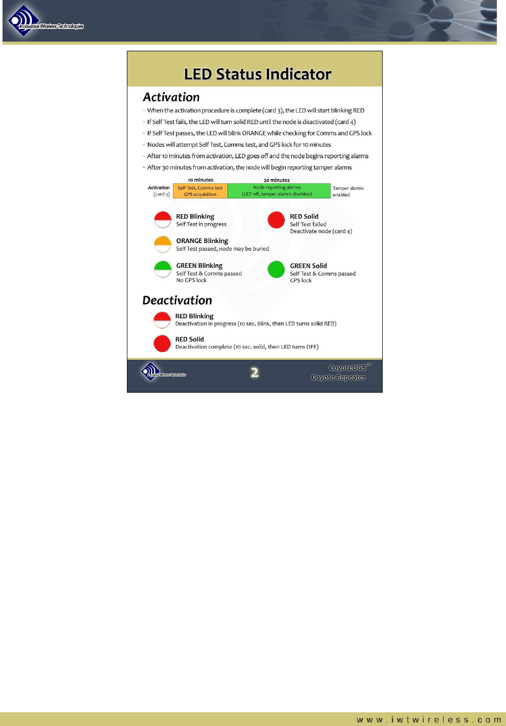
A summary of the LED Status Indicators can be found on the Coyote LED Status Indicator Field Guide. This
can be seen in Figure 6.
FOR OFFICIAL USE ONLY 8
Figure 6 – Coyote UGS LED Status Indicator Field Guide
4. Deactivation Procedure
A Coyote UGS node can be deactivated after it has been activated by following a simple procedure that turns it
off. This procedure is virtually identical to the activation procedure.
4.1. Deactivation Steps
The deactivation steps require no additional equipment or tooling.
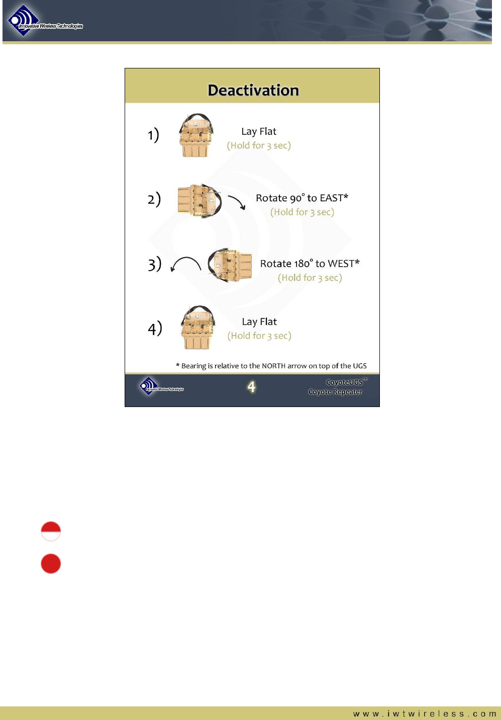
5) The first step is to hold the Coyote UGS node flat and hold this position for 3 seconds.
6) The second step is to rotate the Coyote UGS node 90 degrees to the EAST* and hold this position for 3
seconds.
7) The third step is to rotate the Coyote UGS node 180 degrees to the WEST and hold this position for 3
seconds.
8) The last step is to return the Coyote UGS node to a flat position and hold this for 3 seconds.
* Note – The NORTH bearing is relative to the “N” arrow on top of Coyote UGS housing
The Coyote Deactivation Field Guide lists these steps and is accompanied by images of the Coyote UGS nodes
for ease of use in the field. This can be seen in Figure 7.
FOR OFFICIAL USE ONLY 9
Figure 7 – Coyote UGS Deactivation Field Guide
4.2. LED Status Indicator
When the deactivation procedure has been successfully completed, the tri-color LED on top of the Coyote UGS
node will begin blinking RED for 10 seconds. After the LED blinks RED for 10 seconds, it will turn solid RED for
another 10 seconds before shutting off. Once the LED has turned off, the Coyote UGS is deactivated.
RED Blinking – Indicates that deactivation is now in progress (Blinks for 10 seconds)
RED Solid – Indicates that the deactivation process is complete (Turns off after 10 seconds)
FOR OFFICIAL USE ONLY 10
5. Emplacement Procedure
Once the Coyote UGS node has been sucessfully activated, it is ready for emplacement. The high level steps
for emplacing a Coyote UGS node after it has been activated are:
1) Connect any Sensor Accessories
2) Dig the Hole and Emplace the Coyote UGS node
3) Bury the Node and Camouflage it
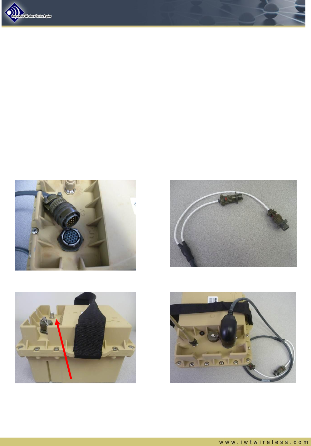
5.1. Connecting Sensor Accessories and RF Antenna
To connect any external sensor accessories to the Coyote UGS node:
a) Connect the male end of the umbilical cable to port J1 on the Coyot eUGS node
b) Connect the female end of the umbilical cable to a MIDs Accessory
c) Connect the RF antenna to port A1 of the Coyote UGS node
Plug pin end into J1 receptacle on UGS
Node (a)
Plug socket end into receptacle on MIDs Accessory
Antenna port A1 (c)
PIR connect to J2 or J3 on MIDs Accessory (b)
Figure 8 - Connecting Coyote UGS antenna and accessories
FOR OFFICIAL USE ONLY 11
5.2. Digging the Hole and Emplacing the Coyote UGS Node
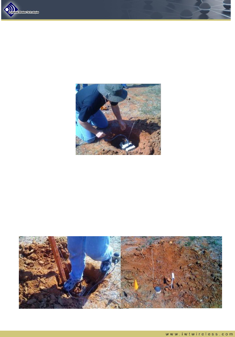
The first step is to dig a hole to bury the Coyote UGS node. General guidelines for digging holes:
a) Select a suitable location for node emplacement
b) Dig a hole 12” (depth may be approximated ±1”) deep and twice the size of the Coyote UGS sensor
c) The base of the hole should be flat
Figure 9 – Coyote UGS node being emplaced in hole
5.3. Bury and Camouflage the Coyote UGS Node
Now that the CoyoteUGS node has been successfully activated and emplaced in a hole, it is ready to be buried
and camouflaged. Good seismic coupling is a key to optimal performance; therefore, care should be taken in
this step to ensure this. General guidelines for burying and camouflaging:
a) Ensure the base of the hole is flat and the base of the sensor is flat against the bottom of the 12” deep
hole. Note: As a quick field measurement guide, the UGS enclosure is ~6” high and it is approximately
another 6” to the base of the thicker part of the antenna
b) Repeatedly pack the dirt around the sensor as the hole is being filled. This will remove air pockets
around the sensor and enhance coupling of the earth to the enclosure
Figure 10 - Tightly pack soil around node during burial procedures
FOR OFFICIAL USE ONLY 12
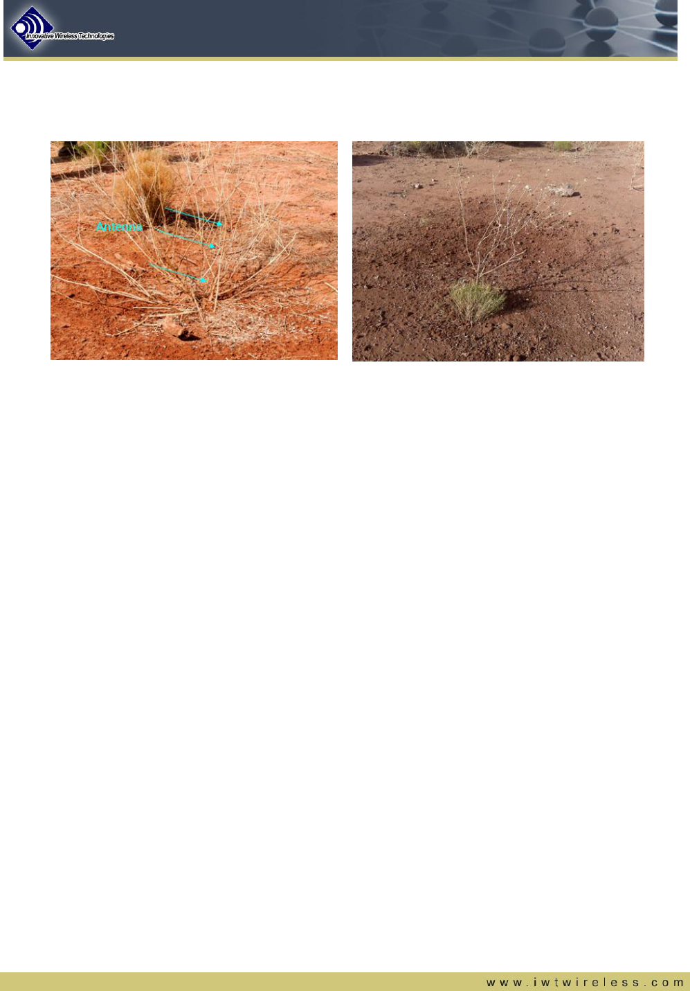
c) Conceal the exposed components of the sensor with natural vegetation
d) The antenna is flexible and can be mildly bent to shape it into the natural surroundings.
Figure 11 - Sensor camouflage using natural vegetation
6. Extraction Procedure
In the event a Coyote UGS node needs to be moved to a new location, the following steps should be taken to
successfully extract the node.
1) The first thing to do is locate and dig up the node. Special care is necessary when using a shovel or
other field implement to prevent accidental damage to the connectors on top of the Coyote UGS node.
2) Grasp and pull on the cloth strap on the top of the unit to aid in extraction. DO NOT use the antenna as
a handle.
3) Once the Coyote UGS node has been moved, a tamper alarm will be triggered.
4) Brush off any dirt that is covering the LED and execute the Coyote UGS Deactivation Procedure*.
* Note – The deactivation procedure must be completed within 5 minutes of removing
the node or else a tamper action will occur

FOR OFFICIAL USE ONLY 13
7. Safety Information
7.1. FCC Notice
FCC ID: SP8-FAP4100-010
CAUTION: Changes or modifications to the equipment not expressly approved by Innovative Wireless
Technologies, Inc. could void the user’s authority to operate the equipment.
Innovative Wireless Technologies, Inc.
1047 Vista Park Drive
Forest, VA 24551
(434) 316-5230
IMPORTANT NOTE: This equipment complies with FCC/IC radiation exposure limits. In order to comply with
these requirements, the antenna used for this device must not be co-located or operating in conjunction with any
other antenna or transmitter, except in accordance with FCC/IC multi-transmitter product procedures.
The Coyote UGS must be installed 20 cm or more from any personnel in order to comply with FCC exposure
requirements.
7.2. Industry Canada (IC) Notice
IC: 9568A-FAP4100010
The term “IC” before the equipment certification number signifies that the Industry Canada technical
specifications were met.
This device complies with RSS-210 Issue 8 and RSS-Gen Issue 3 of the IC Rules.
Le présent appareil est conforme aux CNR d'Industrie Canada applicables aux appareils radio exempts de
licence. L'exploitation est autorisée aux deux conditions suivantes : (1) l'appareil ne doit pas produire de
brouillage, et (2) l'utilisateur de l'appareil doit accepter tout brouillage radioélectrique subi, même si le brouillage
est susceptible d'en compromettre le fonctionnement.
8. Revision History
Revision
Date
Changes
Author
A
11/9/08
Initial Release
K. Colling
B
6/22/09
Release
J. Grohs
C
8/4/11
Updated to reflect Generation 2 hardware
J. Colling
D
4/11/12
Added FCC and IC safety information
J. Colling
E
4/12/12
Updated FCC and IC safety information
J. Colling