Innovative Wireless Technologies FAP5015-050 903-927MHz Transmit Becon for Tracking System User Manual CERTIFICATE OF COMPLIANCE
Innovative Wireless Technologies, Inc. 903-927MHz Transmit Becon for Tracking System CERTIFICATE OF COMPLIANCE
User Manual

Rhein Tech Laboratories, Inc. Client: IWT
360 Herndon Parkway Model #: FAP5015-050
Suite 1400 Standards: FCC 15.247/RSS-210
Herndon, VA 20170 FCC ID: SP8-FAP5015-050
http://www.rheintech.com Report #: 2011183
Page 32 of 36
Appendix L: Manual
Please refer to the following pages.

Page 1 of 10
Issuer: IWT, Inc. Doc. Num.: 6650-11-0040 Rev: A
Revised: Dec 15, 2011
Approval:
INSTALLATION AND USER’S GUIDE
FOR
SENTINEL BEACON
FAP5015-050
Innovative Wireless Technologies, Inc.
1047 Vista Park Drive, Suite A
Forest, VA 24551
Phone: (434)316-5230
Fax: (434)316-5232
www.iwtwireless.com

Page 2 of 10
Issuer: IWT, Inc. Doc. Num.: 6650-11-0040 Rev: A
Revised: Dec 15, 2011
Approval:
Contents
1.PRODUCT OVERVIEW.................................................................................................... 3
2.SAFETY INFORMATION ................................................................................................ 3
2.1Requirements for FCC Compliance .................................................................................... 3
2.2Requirements for MSHA Compliance ................................................................................ 4
3.SPECIFICATIONS FOR FAP5010-001 ............................................................................ 5
4.DESCRIPTION................................................................................................................... 6
4.1Outputs ................................................................................................................................ 6
4.2Components Necessary for Installation .............................................................................. 6
5.PRIOR TO INSTALLATION ............................................................................................ 7
5.1Site Survey .......................................................................................................................... 7
5.2Visually inspect each Sentinel Beacon to ensure that: ........................................................ 7
6.INSTALLATION INSTRUCTIONS.................................................................................. 7
6.1Installations Below Ground ................................................................................................ 7
6.1.1Antenna Placement ............................................................................................................. 7
6.1.2Applying Power to the Sentinel Beacon ............................................................................. 8
6.1.3Sentinel Beacon Enclosure Placement ................................................................................ 9
6.2Installations Above Ground ................................................................................................ 9
6.2.1Sentinel Beacon Installation Instructions ............................................................................ 9
7.OPERATING AND MAINTENANCE INSTRUCTIONS .............................................. 10

Page 3 of 10
Issuer: IWT, Inc. Doc. Num.: 6650-11-0040 Rev: A
Revised: Dec 15, 2011
Approval:
1. PRODUCT OVERVIEW
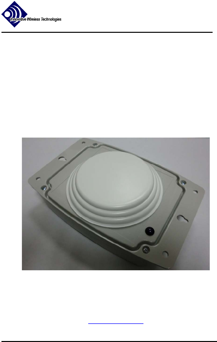
Innovative Wireless Technologies’ Sentinel Beacon is a transmitter intended primarily for use in
industrial mining applications. The FAP5015-050 Sentinel Beacon design provides enhanced
tracking for miners and equipment in high-traffic areas of a coal mine.
2. SAFETY INFORMATION
IMPORTANT INFORMATION ON SAFE OPERATION. READ THIS INFORMATION
BEFORE INSTALLING AND OPERATING THE SENTINEL BEACON.
2.1 Requirements for FCC Compliance
Changes or modifications to this unit not expressly approved by Innovative Wireless
Technologies (IWT) may void the user’s authority to operate this equipment.
FCC ID: SP8-FAP5015-050
This device complies with Part 15 of the FCC Rules. Operation is subject to the following two
conditions:
1. This device may not cause harmful interference.
2. This device must accept any interference received, including interference that may cause
undesired operation.
Le présent appareil est conforme aux CNR d'Industrie Canada applicables aux appareils radio
exempts de licence. L'exploitation est autorisée aux deux conditions suivantes : (1) l'appareil ne
doit pas produire de brouillage, et (2) l'utilisateur de l'appareil doit accepter tout brouillage
radioélectrique subi, même si le brouillage est susceptible d'en compromettre le fonctionnement.
IMPORTANT NOTE: To comply with FCC RF exposure compliance requirements, the
antenna used for this transmitter must not be co-located or operating in conjunction with any
other antenna or transmitter.
The Sentinel Beacon must be installed 20cm or more from any personnel in order to comply with
FCC exposure requirements.
NOTE: This equipment has been tested and found to comply with the limits for a Class B digital
device, pursuant to Part 15 of the FCC Rules. These designed limits provide reasonable
protection against harmful interference in a residential installation. This equipment generates,
uses, and can radiate radio frequency energy and, if not installed and used in accordance with the
instructions, may cause harmful interference to radio communications. However, there is no

Page 4 of 10
Issuer: IWT, Inc. Doc. Num.: 6650-11-0040 Rev: A
Revised: Dec 15, 2011
Approval:
guarantee that interference will not occur in a particular installation. If this equipment does
cause harmful interference to radio or television reception, which can be determined by turning
the equipment off and on, the user is encouraged to try to correct the interference by one or more
of the following measures:
-- Reorient or relocate the receiving antenna.
-- Increase the separation between the equipment and receiver.
-- Connect the equipment into an outlet on a circuit different from that to which the receiver is
connected.
-- Consult the dealer or an experienced radio/TV technician for help.
2.2 Requirements for MSHA Compliance
This device has been evaluated by the Mine Safety and Health Administration (MSHA) per Title
30 Code of Federal Regulations Part 23.
MSHA Intrinsic Safety Evaluation Number: 23-XXXXXX
Per MSHA’s evaluation, this product has been determined to be intrinsically safe and may be
used in areas where permissible equipment is required under the following conditions:
The Sentinel Beacon is approved for use by MSHA with the following C size batteries
ONLY: Duracell MN1400, PL1400, Energizer E93
Do NOT mix batteries of different types or manufacturers.
Replace both batteries at the same time.
The Sentinel Beacon’s antenna must be located greater than 3.3 feet from blasting
circuits.
Where magnetic mounting is used for the Sentinel Beacon, the magnets must comply
with MSHA Program Information Bulletin (PIB) 09-36 which states permanent magnets
may not be used in the same mining section as remote control equipment using Hall-
effect switches.
The Sentinel Beacon is approved for use by MSHA with the (non-detachable) Astron Wireless:
NP91WGIR3MMX9I.

Page 5 of 10
Issuer: IWT, Inc. Doc. Num.: 6650-11-0040 Rev: A
Revised: Dec 15, 2011
Approval:
3. SPECIFICATIONS FOR FAP5010-001
ENVIRONMENTAL
Operating Temperature -30C to +60C ambient
1
Storage Temperature -40C to +80C ambient (without
batteries)
Dimensions 7.6” x 5.1” x 2.25”
Weight 1 lb (without batteries)
Enclosure IP65
POWER
Battery
Type Alkaline C cells (x2)
ELECTRICAL
Frequency Range 902 – 928 MHz
RF Transmit Power +10 dBm
Note 1: Operating at extreme temperatures may influence the battery life of the Sentinel
Beacon. To maximize battery life, maintain operating temperatures in the range +15C to +35C.

Page 6 of 10
Issuer: IWT, Inc. Doc. Num.: 6650-11-0040 Rev: A
Revised: Dec 15, 2011
Approval:
4. DESCRIPTION
4.1 Outputs
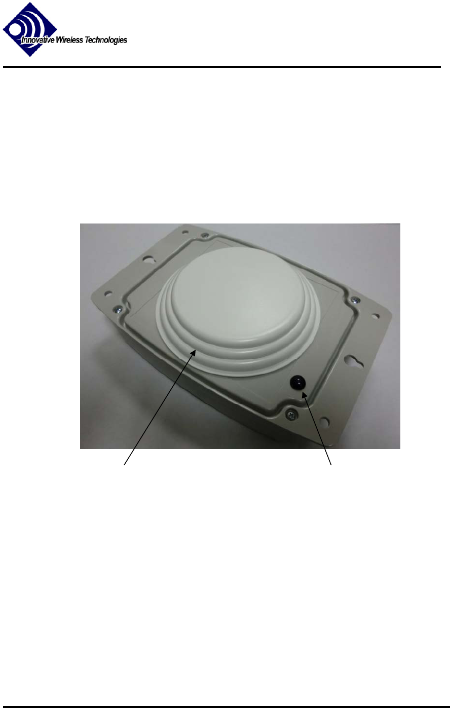
The following is an explanation of the Sentinel Beacon outputs shown in Figure 1:
LED: The blue power LED indicates the status of the Sentinel Beacon (see
section 7.0)
FIGURE 1: SENTINEL BEACON
4.2 Components Necessary for Installation
The Sentinel Beacon installation uses the following components and accessories (see sections 5.0
and 6.0 for installation instructions):
C Cell Alkaline Batteries:
Two C cell alkaline primary batteries power the Sentinel Beacon. The batteries are located in the
battery holders inside the enclosure. Battery maintenance and replacement details are in section
7.
LED Non-Removable Antenna

Page 7 of 10
Issuer: IWT, Inc. Doc. Num.: 6650-11-0040 Rev: A
Revised: Dec 15, 2011
Approval:
Magnetic Mounting Feet:
The Sentinel Beacon includes holes for three magnetic mounting feet for quick installation. The
mounting feet screw into the base of the enclosure. In areas of the mine where magnets are not
permitted (per MSHA PIB 09-36), cable ties may be used.
5. PRIOR TO INSTALLATION
5.1 Site Survey
Conduct a survey to determine the appropriate sites to install the Sentinel Beacon from an RF
perspective.
5.2 Visually inspect each Sentinel Beacon to ensure that:
The enclosure is free from damage or defects.
Four screws properly secure the enclosure lid.
6. INSTALLATION INSTRUCTIONS
6.1 Installations Below Ground
IMPORTANT NOTE:
TRAINED PERSONNEL MUST PROFESSIONALLY INSTALL THE SENTINEL
BEACON. FOLLOW ALL MSHA REQUIREMENTS SPECIFIED IN SECTION 2.2.
At each of the sites determined by the survey described in 5.1:
6.1.1 Antenna Placement
Determine the placement for the 900 MHz antenna to ensure proper RF propagation. For units
installed in coal mines below ground, mount the antennas to roof bolts using the magnetic
antenna mount. Select locations that ensure proper RF communication. Antenna location should
not present a safety hazard or opportunity for damage to occur.
Per the Institute of Makers of Explosives (IME) Safety Library Publication No. 20, the
recommended clearance distance between the Sentinel Beacon’s antenna and any blasting circuit
is a minimum 3.3 feet.

Page 8 of 10
Issuer: IWT, Inc. Doc. Num.: 6650-11-0040 Rev: A
Revised: Dec 15, 2011
Approval:
6.1.2 Applying Power to the Sentinel Beacon
Battery installation must be performed above ground prior to installing the Sentinel Beacon in a
mine. Refer to section 2.2 for MSHA guidelines and warnings associated with the Sentinel
Beacon Batteries. Only the following C cell batteries may be used with the Sentinel Beacon:
Duracell MN1400, PL1400 or Energizer E93
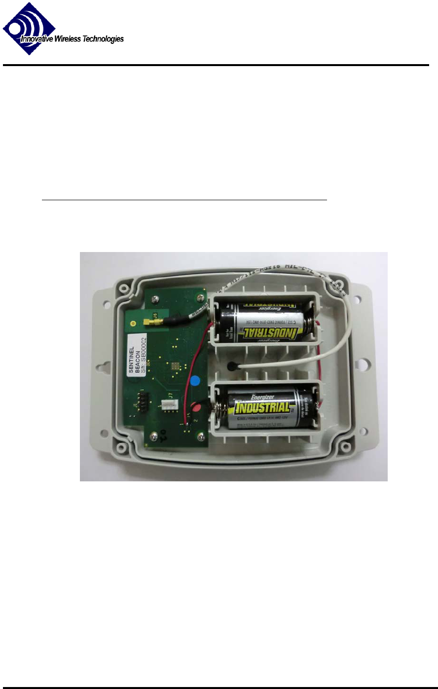
Remove the enclosure lid of the Sentinel Beacon. Insert two C cell batteries into the battery
holder. Be sure to check for proper polarity when inserting batteries (see polarity instructions in
Figure 2).
FIGURE 2: POWERING THE SENTINEL BEACON
(SHOWN WITH BATTERIES INSTALLED)
Remove and replace the enclosure lid gasket. Observe proper orientation when re-installing the
enclosure lid. Secure the lid with all four screws.
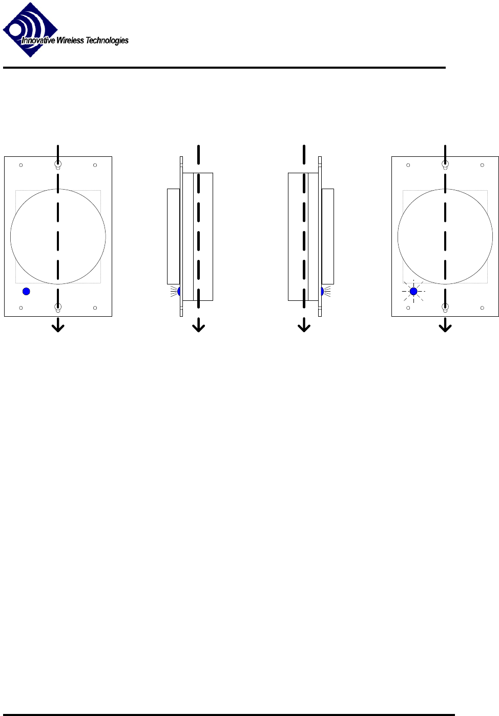
Step1: Hold the beacon level with the antenna facing up and the (narrow) end with the LED
towards you. Maintain this position for 4-5 seconds.
Step2: Tilt the (long) side nearest the LED downward so the antenna faces left. Maintain this
position until the LED flashes once (about 5seconds).
Step3: Tilt the unit 180 degrees about the same axis so that the antenna is facing right. Maintain
this position until the LED flashes once.

Page 9 of 10
Issuer: IWT, Inc. Doc. Num.: 6650-11-0040 Rev: A
Revised: Dec 15, 2011
Approval:
Step4: Return to the unit to the original position so that the antenna is facing up. Maintain this
position unit the LED begins flashing short pulses at 500ms intervals. This indicates the unit is
transmitting.
ANTENNA
LED
Toward You
ANTENNA
Toward You
ANTENNA
Toward You
ANTENNA
LED
Toward You
STEP1 STEP2 STEP3 STEP4
FIGURE 3: TURNING THE SENTINEL BEACON ON
6.1.3 Sentinel Beacon Enclosure Placement
Locate a place to mount the Sentinel Beacon enclosure. Use the enclosure’s magnetic mounting
feet to mount the Beacon to a roof bolt plate (or other acceptable location). The Sentinel Beacon
should be mounted with the antenna disk in a horizontal orientation such that the antenna and the
LED are facing away from the roof or other horizontal mounting surface.
In areas of the mine where magnets are not permitted (per MSHA PIB 09-36), cable ties may be
used to mount the Sentinel Beacon.
6.2 Installations Above Ground
At each of the sites determined by the survey described in 5.1:
6.2.1 Sentinel Beacon Installation Instructions
Follow installation instructions of 6.1. Equipment above ground should be located so as not to
present a safety hazard or cause damage. Secure all equipment using the proper hardware.
Follow all FCC guidelines listed in Section 2.0.

Page 10 of 10
Issuer: IWT, Inc. Doc. Num.: 6650-11-0040 Rev: A
Revised: Dec 15, 2011
Approval:
7. OPERATING AND MAINTENANCE
INSTRUCTIONS
The Sentinel Beacon does not have any direct user interface.
Monitor the status of the Sentinel Beacon by observing the LED mounted on the outside of the
enclosure (LED1):
BLINK (ON—1 ms, OFF—500 ms): Power ON / Device transmitting
OFF: Power OFF / Device not transmitting
The Sentinel Beacon requires little routine maintenance. Inspect each box periodically every 3-6
months to ensure that the box remains free of defects. It is important that the box remains dust
tight. Replace defective boxes immediately. Do not continue to use any boxes that may have
had their dust seal compromised.
Replace the C cell batteries inside the Sentinel Beacon enclosure once each year. Refer to
Section 2.2 for MSHA requirements pertaining to the batteries. To prevent dust and moisture
from entering the Sentinel Beacon enclosure during battery replacement, replace the batteries in
a location above ground and free from excessive moisture and coal dust.
To replace the Sentinel Beacon’s batteries:
1. Prior to removing the enclosure’s lid, wipe surfaces of enclosure to remove excess
dirt/dust.
2. Remove enclosure lid by unscrewing the four lid screws.
3. Remove the two C cell batteries from the battery holders.
4. Insert two fresh C cell batteries into the battery holders noting proper polarity.
5. Replace the enclosure lid gasket.
6. Replace enclosure lid and secure all four lid screws.
At this point the beacon will be in a non-operational, battery conserving mode. To initiate
normal operation of the beacon, follow the instructions in Section 6.1.2.