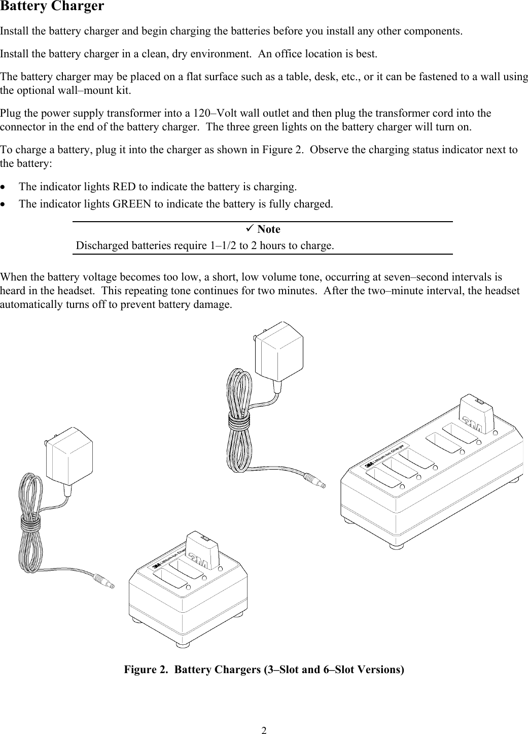
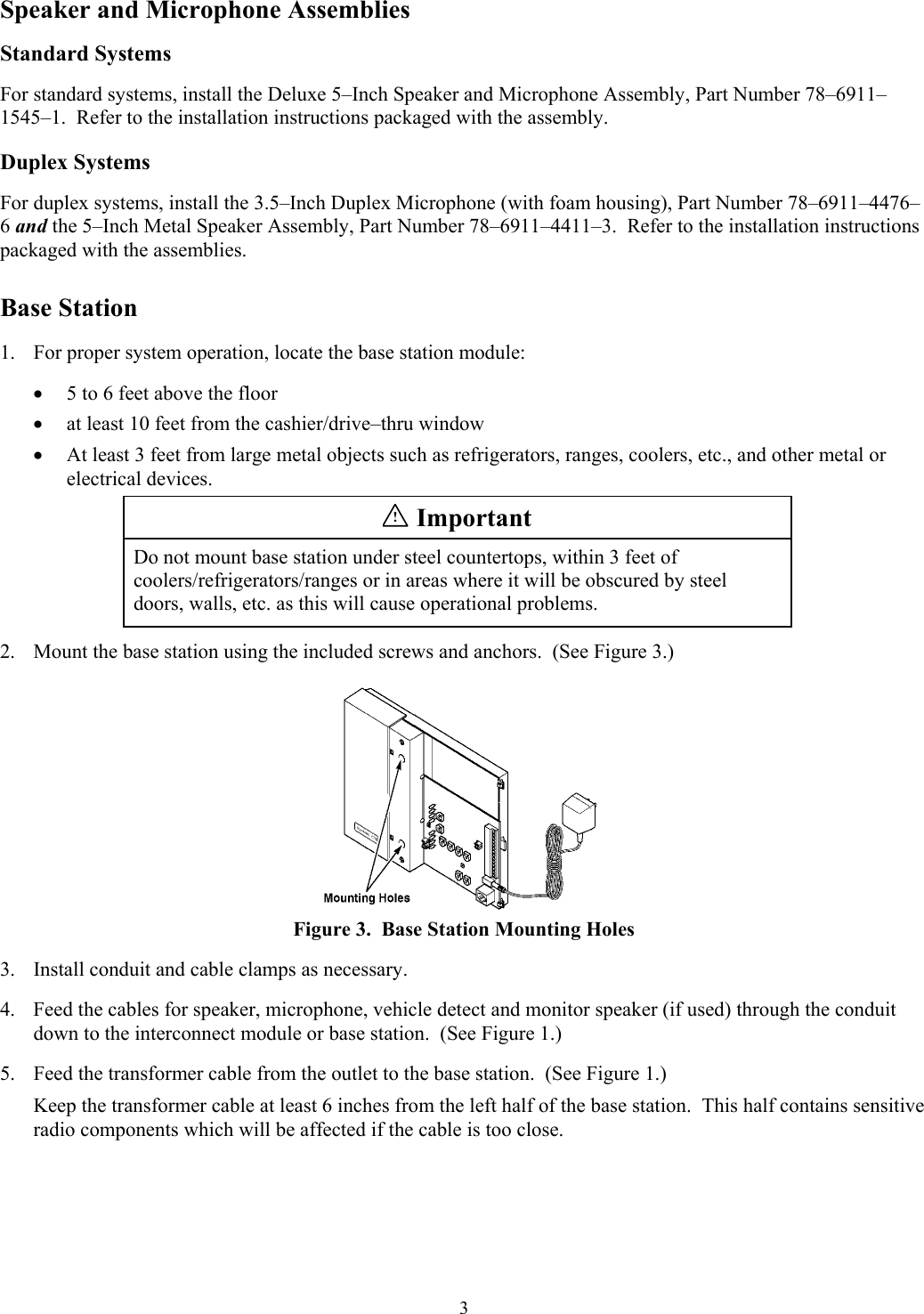
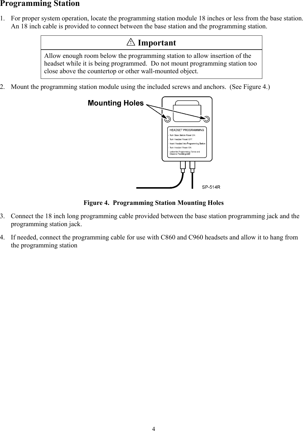
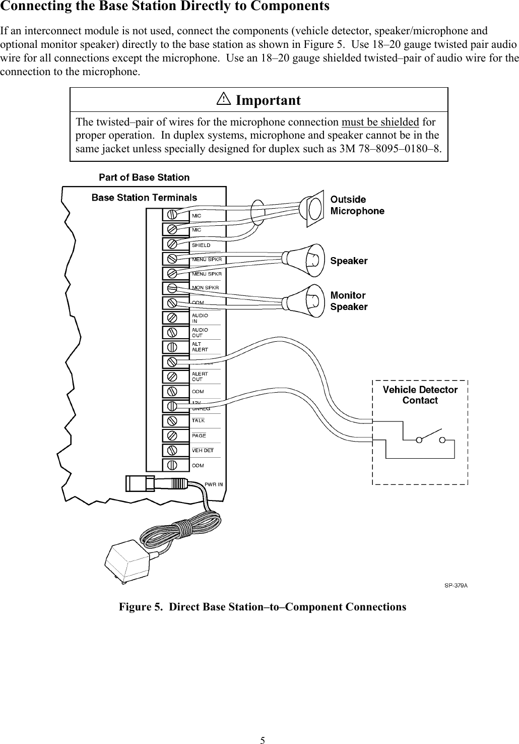
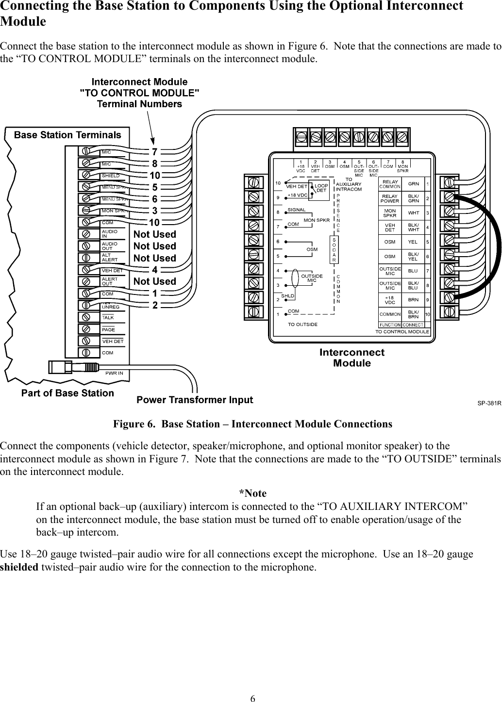
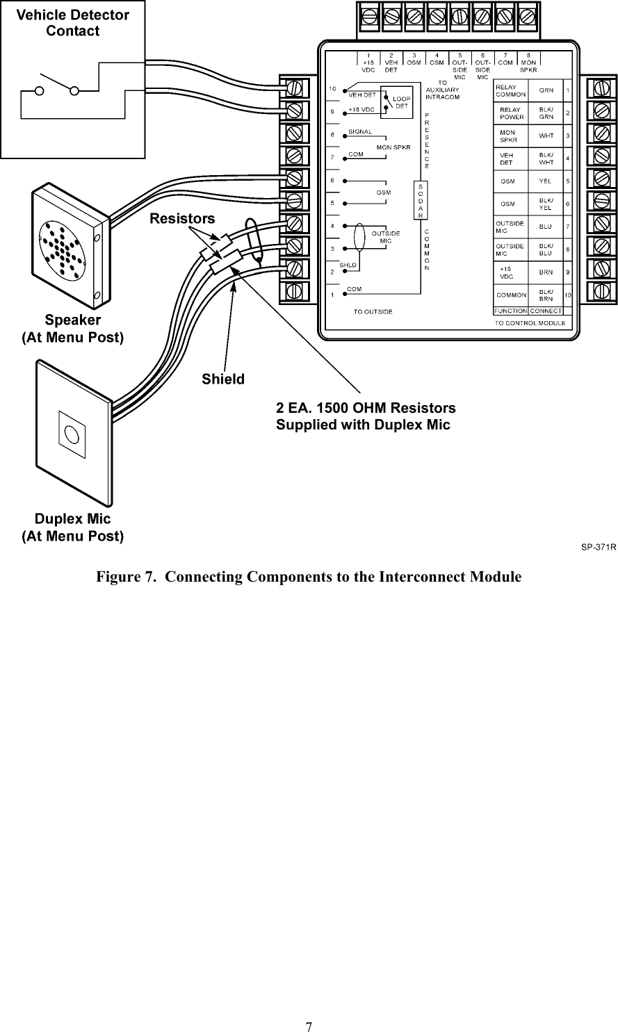
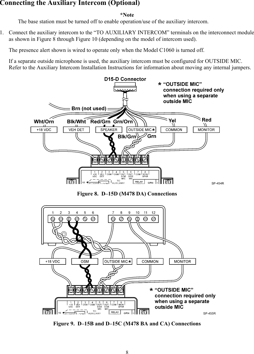
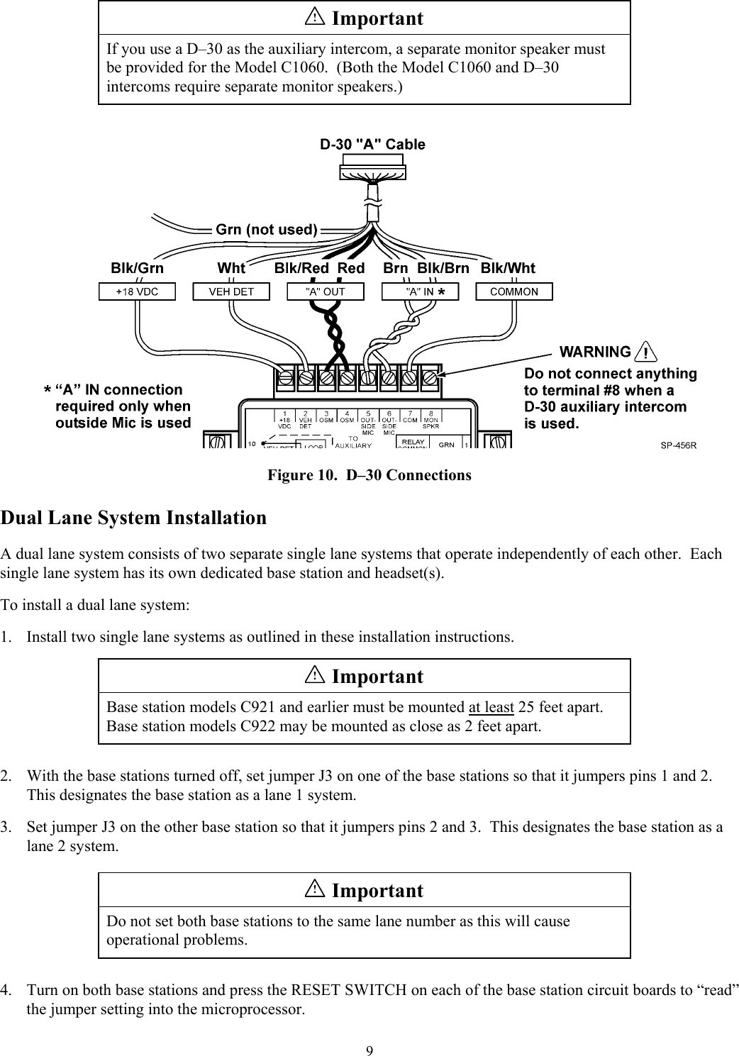
Inovonics Wireless 3B63MB4 HC922AA Wireless Intercom Base Station User Manual C1060Ins
Inovonics Wireless Corporation HC922AA Wireless Intercom Base Station C1060Ins
UserManual.wiki
>
Inovonics Wireless
>
3B63MB4 User Manual
Users Manual
Navigation menu
Upload a User Manual
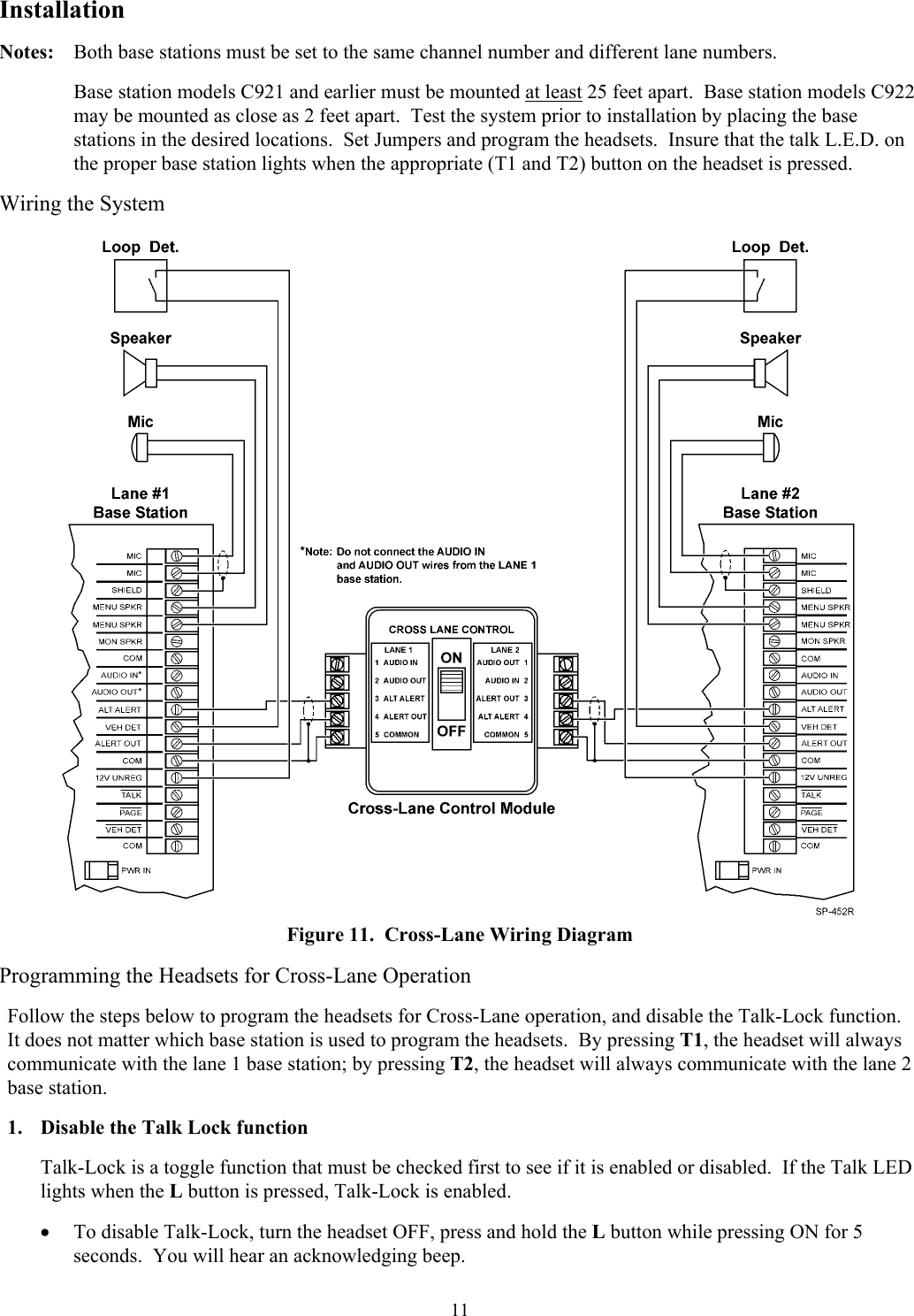
Namespaces
Wiki Guide
HTML
PDF
Info
Views
User Manual
Discussion / Help
Navigation