Inovonics Wireless 3B64X9RU1 Waterproof Senior Living Pendant User Manual 06536E
Inovonics Wireless Corporation Waterproof Senior Living Pendant 06536E
Users Manual
2/1/18 06536E © Inovonics, 2018 - www.inovonics.com
EN1221S-60 Waterproof Pendant
Installation and Operation Manual
1 Overview
The Inovonics waterproof pendant is small, light and comfortable to wear,
and provides advanced functionality and reliability to enhance the user
experience.
The waterproof pendant is available in the following configurations:
Note: For UL 2560 installations, refer to the EN6080 Area Control Gateway
Installation Instructions or the EN6040-T Network Coordinator with
Transformer Installation Instructions.
1.1 Inovonics Contact Information
If you have any problems with this procedure, contact Inovonics technical
services:
• E-mail: support@inovonics.com.
• Phone: 1.800.782.2709, option 2.
1.2 Maximum Number of Repeaters for a UL 2560
Installation
To achieve the 99.99% alarm message reliability required for UL 2560
compliance, system installations must operate within the following limits for
end device and repeater counts.
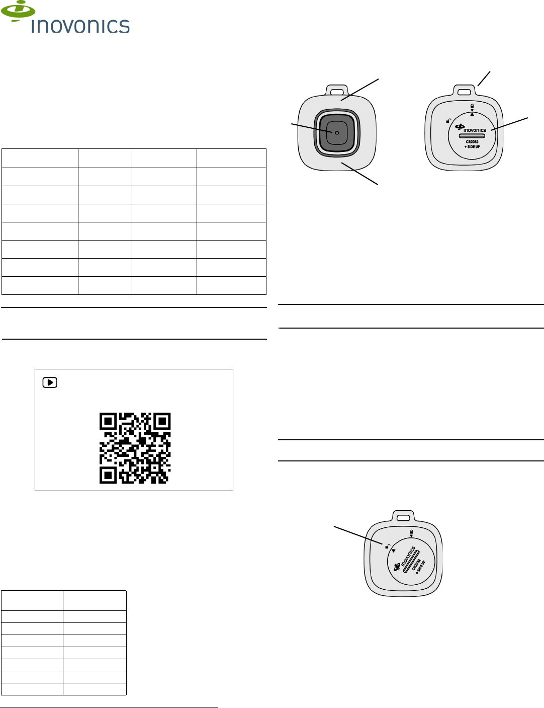
1.3 Pendant Components
Figure 1 Pendant components (waterproof pendant with neck lanyard
shown)
1.4 What’s In The Carton
Individually-packaged products include the following items:
• One unattached lanyard or one attached wristband
• One CR2032 coin cell battery
• One battery door
Note: Bulk-packaged products are shipped with multiples of the above
items.
2 Installation and Startup
2.1 Installation Notes
• These products are designed to be maintained by professional
technicians.
• Products are intended for indoor use.
• All products should be manually tested weekly (see section 6, “Test
the Transmitter”).
2.2 Battery Installation
Caution: If you are installing batteries in multiple devices, keep the
batteries from coming into contact with each other to prevent discharge.
1. Place the battery in the battery compartment, ensuring that the positive
terminal (+) faces up.
2. Seat the battery door over the battery so that the arrow on the battery
door is lined up with the unlocked padlock icon.
Figure 2 Battery door in the unlocked position
Part # Check-In Location Other
EN1221S-60N 60 minutes North America Neck lanyard
EN1221S-60AN 60 minutes Australia Neck lanyard
EN1221S-60ZN 60 minutes New Zealand Neck lanyard
EN1221S-60W 60 minutes North America Wristband
EN1221S-60WL 60 minutes North America Long wristband
EN1221S-60AW 60 minutes Australia Wristband
EN1221S-60ZW 60 minutes New Zealand Wristband
For product and installation videos visit us at
www.inovonics.com/videos or use the QR
code below.
End Devices Maximum
Repeaters
150 397
250 386
350 375
500 360
1000 313
2000 238
3000 184
AActivation button BTransmit and alarm clear
LED
CLow battery LED
DBattery door EAttachment loop
B
C
AD
E
Unlocked
position
2/1/18 06536E © Inovonics, 2018 - www.inovonics.com 2
3. Use the ACC680 alarm clearance card or a quarter to turn the battery
door to line up the arrow on the battery door with the arrow under the
locked padlock icon.
Figure 3 Battery door in the locked position
4. Press the activation button for at least one second.
• The red LED will flash and the pendant will vibrate, indicating that an
alarm has been sent. (For more information, see section 3.1, “Send an
Alarm” on page 2.)
5. Clear the alarm sent when you activated the pendant per section 3.2,
“Clear an Alarm”.
2.3 Register the Transmitter
The transmitter sends a check-in message to the receiver or gateway every
60 minutes for the purposes of supervision. The transmitter must be
registered and supervised.
Caution: The EN1221S-60 waterproof pendant must have a supervision
window of no more than 12 hours to help ensure discovering a missing
device within 24 hours.
Each transmitter has a unique factory-programmed identification number.
Refer to the receiver or gateway's installation instructions for details on
registering and setting up supervision.
6. When prompted by the receiver or gateway to reset transmitter, press
the activation button, and then clear the alarm per section 3.2, “Clear an
Alarm”.
Caution: The transmitter should be tested after registration to ensure
operation. See section 6, “Test the Transmitter”.
2.4 Wear the Transmitter
The pendant transmitter can be worn in three ways:
• Around the neck with the neck lanyard, which is included with the
waterproof pendant with neck lanyard.
Caution: The neck lanyard included with the waterproof pendant is
designed with a breakaway feature for user safety. Substitution of a
stronger cord or chain may result in injury to the wearer.
• On the arm with the wristband, which comes attached on the
waterproof pendant with wristband.
• On the belt, using the optional ACC683 belt loop attachment kit.
Neck Lanyard
To attach the neck lanyard:
7. Secure the lanyard to the pendant’s attachment loop with a simple girth
hitch knot.
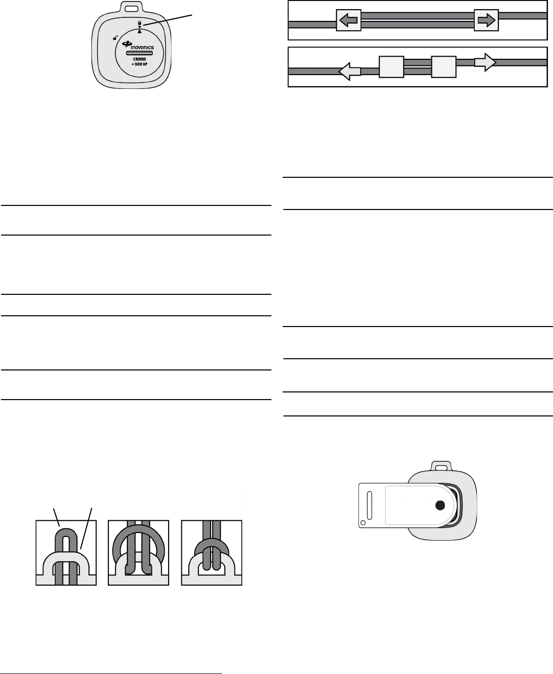
Figure 4 A simple girth hitch knot
8. Adjust the neck lanyard to the wearer’s neck size.
• Pull both slide adjustment tabs on the lanyard to reduce the length of
the cord.
• Pull both sides of the lanyard cord to increase the length of the cord.
Figure 5 Adjust the neck lanyard
Wristband
The wristband comes attached to the waterproof pendant with wristband.
The wristband is a standard 16mm width, allowing for replacement with a
wristband of the user’s choice. The standard length wristband is designed
to fit wrist circumferences from 5.5 to 7.5 inches; the long wristband is
designed to fit wrist circumferences from 6.5 to 9.25 inches.
Note: Replacement wristbands must be of a similar thickness to the
provided 16mm wristband. Metal expansion bands will not attach reliably to
the device.
3 Operate the Transmitter
3.1 Send an Alarm
To send an alarm:
1. Press the activation button for at least one second.
• When activated, the pendant will vibrate briefly and the red
transmission LED will blink rapidly for the first five seconds, and then
slowly until the alarm is cleared.
3.2 Clear an Alarm
Note: After sending an alarm, an end user can send a subsequent alarm
once ten seconds have elapsed, even if the initial alarm has not been
cleared on the device.
There are two ways to clear an alarm:
Using the Alarm Clearance Card
Note: The ACC680 alarm clearance card is an optional accessory sold
separately.
1. Place the dot on the ACC680 alarm clearance card over the activation
button.
• The red transmission LED will cease flashing and the blue alarm clear
LED will flash quickly six times to indicate the alarm has cleared.
Figure 6 Place the alarm clearance card over the activation button
Using a Button Press Pattern
1. Press the activation button three times, quickly.
2. When the blue LED flashes twice, press the activation button three
more times, quickly.
• The blue alarm clear LED will flash quickly six times to indicate the
alarm has cleared.
Locked
position
Cord
Attachment
loop
Tighten
Loosen

2/1/18 06536E © Inovonics, 2018 - www.inovonics.com 3
3.3 Low Battery Alert
When a low battery is detected, the transmitter will send a low battery alert,
and start a seven day countdown. If the battery has not been replaced
within two days from when the low battery alert message was sent, the
yellow low battery LED on the bottom of the pendant will begin to blink, and
will not stop until the battery is replaced, or the seven day countdown
expires.
If the seven day countdown expires without the battery being changed, the
pendant will automatically go into storage mode. For more about storage
mode, see section 5, “Storage Mode”.
4 Battery Replacement
Note: Inovonics has tested and recommends Panasonic®, Energizer® and
FDK® (formerly Sanyo) CR2032 coin cell batteries.
The waterproof pendant uses one standard CR2032 coin cell battery. To
change the battery:
1. Use the ACC680 alarm clearance card or a quarter to turn the battery
door to the unlocked padlock icon.
2. Remove the battery door.
3. Remove the old battery from the battery compartment.
4. Place the new battery in the battery compartment, ensuring that the
positive terminal (+) faces up.
5. Seat the battery door over the battery so that the arrow on the battery
door is lined up with the unlocked padlock icon.
6. Use the ACC680 alarm clearance card or a quarter to turn the battery
door to line up the arrow on the battery door with the arrow under the
locked padlock icon.
7. Press the activation button to initalize the transmitter.
8. Clear the resulting alarm per section 3.2, “Clear an Alarm”.
Note: If the pendant is not activated after replacing the battery, the low
battery indication will not clear until the next check-in interval.
5 Storage Mode
Storage mode is an ultra low battery state designed to protect the life of the
internal backup battery. The pendant is shipped from Inovonics in storage
mode. If the waterproof pendant transmitter will go unused for any
significant period, it should be put in storage mode. The device will also
automatically go into storage mode at the next check-in transmission time if
the coin cell battery has been removed.
Note: When the pendant is in storage mode, it will not transmit alarms or
check-in messages.
5.1 Put the Device in Storage Mode
Note: The device should not be left in storage mode for more than 12
months. Devices should be stored in ambient conditions (69 to 73 degrees
Fahrenheit).
To put the device in storage mode:
1. Use the ACC680 alarm clearance card or a quarter to turn the battery
door to the unlocked position.
2. Remove the battery from the battery compartment.
3. Press the activation button for at least one second.
• The red LED will flash and the pendant will vibrate briefly to indicate
that an alarm has been sent. This serves as confirmation that the
pendant is now in storage mode.
4. Seat the battery door over the empty battery chamber, and use the
ACC680 alarm clearance card or a quarter to turn the battery door to
line up the arrow on the battery door with the arrow under the locked
padlock icon.
Note: If the alarm activation button is pressed when the device is in storage
mode and the battery is not installed, a yellow LED will illuminate briefly on
the lower portion of the device to indicate a missing battery condition to the
user.
5.2 Take the Device out of Storage Mode
To remove the device from storage mode:
1. Use the ACC680 alarm clearance card or a quarter to turn the battery
door to the unlocked padlock icon.
2. Remove the battery door.
3. Place a battery in the battery compartment, ensuring that the positive
terminal (+) faces up.
4. Seat the battery door over the battery so that the arrow on the battery
door is lined up with the unlocked padlock icon.
5. Use the ACC680 alarm clearance card or a quarter to turn the battery
door to line up the arrow on the battery door with the arrow under the
locked padlock icon.
6. Press the activation button for at least one second.
• The red LED will flash and the pendant will vibrate briefly to indicate
that an alarm has been sent. This serves as confirmation that the
pendant is no longer in storage mode.
• When the button is pressed, an alarm message and reset message
are sent to the head end application.
7. To cause the red LED to cease flashing, clear the alarm sent when you
activated the pendant per section 3.2, “Clear an Alarm”.
Note: If the alarm activation button is pressed when the device is not in
storage mode and the battery is not installed, the red LED will blink rapidly
for five seconds, the pendant will vibrate, and an alarm will be sent with a
missing battery message. The alarm clearance function is not enabled in
this situation. Subsequent button presses will cause the yellow LED to
illuminate briefly on the lower portion of the device to indicate a missing
battery condition to the user.
6 Test the Transmitter
The transmitter should be tested after registration and then weekly to
ensure operation.
To test the transmitter:
1. Press the activation button for at least one second and ensure the red
transmit LED lights, the vibration activates, and the alarm is received by
the receiver or gateway.
2. Clear the alarm and ensure the red alarm transmission LED stops
flashing, and the blue alarm clear LED flashes.
7 Cleaning and Care
7.1 Cleaning
Caution: Cleaning should only be performed with the battery door in place
and in the locked position.
Cleaning should be performed by hand using a damp cloth and mild soap,
or disinfectant wipes designed for household use.
Do Not Use
The following products should never be used to clean the EN1221S-60
series pendants:
• Strong cleaning agents such as ammonia, bleach, alcohol or
quaternary disinfectant.
• Abrasive or powder cleansers.
• Alcohol-based hand sanitizers.
The following equipment and processes must never be used:
• Steam autoclave or commercial sterilization procedures using heat,
chemical, gas or radiation techniques.
• Dishwasher or washing machine.
• Soaking or suspending the pendant in water or other liquids.
Using any of these products or processes will damage the pendant.
7.2 Care
The plastic used for the pendant is durable and designed to withstand
exposure to most common substances including soaps and skin lotions.
However, there are some types of creams, lotions or sprays which contain
chemicals that may dull the finish of the housing. These include insect
repellents containing DEET, sunscreen and topical analgesics. If an end
user is using these types of products, they should avoid having the
pendant come into direct contact with them.

2/1/18 06536E © Inovonics, 2018 - www.inovonics.com 4
8 Device Indicators
9 Water Exposure
UL has evaluated the EN1221S-60 series pendants to meet the water
spray and submersion tests required
under UL 2560, section 38.
In addition, these pendants meet IP67 certification standards for dust and
water ingress protection, ensuring that:
• Ingress of dust particles does not interfere with the satisfactory
operation of the device.
• There is no harmful effect to the device caused by:
- Submersion up to three feet (one meter) for less than or equal to 30
minutes.
Note: IP67 certification was performed by an independent laboratory not
affiliated with UL.
10 End User Recommendations
The pendant transmitter housing is waterproof up to the IP67 standard
when the battery door is properly seated and in the locked position. The
product is designed for incidental/momentary submersion in water, but not
for extended submersion. As such, we offer the following recommendations
to the end user:
* The pendant is able to successfully transmit an alarm or check-in
message when exposed intermittently to water in a shower setting.
However, when the pendant is fully submerged, the water absorbs the radio
signal such that messages may not be reliably detected by the receiver.
11 Specifications
Dimensions: 1.6" x 1.6" x 0.5" (4 x 4 x 1.25 cm).
Weight: 0.6 oz (17 g) with battery inserted.
Operating temperature: 32 to 140°F (0 to 60°C).
Operating environment: Waterproof to IP67 standard.
Estimated battery life: One year (assuming five alarm activations per day
and alarm clearance within ten minutes of alarm activation).
Battery type: Panasonic CR2032.
Power requirement: 3VDC, 14.5µA.
Storage requirement: Ambient conditions of 69 to 73°F (20.5 to 22.8°C).
Compliance for EN1221S-60AN, EN1221S-60ZN, EN1221S-60AW and
EN1221S-60ZW: AS/NZS 4268:2012 Radio Systems Equipment - Short
Range Devices.
UL certification for EN1221S-60N and EN1221S-60W: UL 2560 (see
conditions below).
Note: For UL 2560 installations, Inovonics repeaters must have 20 minute
check-in times. Inovonics transmitters must have a minimum of 60 minute
check-in times.
Note: In a UL 2560 installation, the EN1221S-60 series pendants may be
used with completed emergency call systems for assisted living and
independent living facilities.
For UL 2560 certified system installations, the following Inovonics
EchoStream devices are approved for installation within maximum system
configuration limits defined in section 1.2 of this document:
• EN6080 area control gateway or EN6040-T network coordinator with
transformer.
• EN5040-20T high power repeater.
• End devices (transmitters) with a minimum 60-minute check-in
interval, as follows:
- Fundamental devices which are subject to UL 2560 certification
(pendant transmitters and OEM products using the Inovonics RF
module).
- Supplemental devices which are not subject to UL 2560 system
certification but which may be used within a UL 2560 certified system
(e.g. universal transmitters and activity sensors).
Alarm
Activation
Alarm
Clearance Low Battery Missing
Battery
LED Color Red Blue Yellow Yellow
LED Pattern
Rapid blink
for five
seconds,
and then
slow blink
until alarm
is cleared
Using
alarm
clearance
card: six
quick
flashes
Using
button
pattern:
two quick
flashes
after first
three
button
presses,
and then
six quick
flashes
after the
next three
button
presses
Blinks
every five
seconds
until battery
is replaced
or until
seven-day
countdown
expires
Steady
glow for
five
seconds,
then stops
Vibration
Patterns
Vibrates for
one second
N/A N/A N/A
More
Information
Section 3.1 Section 3.2 Section 3.3 Section
5.1
Usage Situation OK to Use? Cautions
Shower Yes* Do not spray water directly on the
device at distances of less than 12
inches; avoid spraying water at
extremely high pressure.
Bath Yes* Momentary submersion is
permissible at water temperatures
less than 105°F. Extended
submersion of the device is not
recommended.
Rain Yes* Avoid extended exposure; wear
the device under a sleeve, shirt, or
jacket
Water exercise,
swimming pool,
hydrotherapy/hot
tubs, steam
rooms and
saunas
No Do not use the device during these
activities. Please note that the
IP67 rating does not test for
exposure to liquids with a chemical
content such as chlorine or salt
water. Exposure to elevated water/
air temperatures or humidity levels
in these settings may permanently
damage the device.

2/1/18 06536E © Inovonics, 2018 - www.inovonics.com 5
Note: Users that have achieved certification and will install UL 2560
certified systems are responsible for labeling all fundamental devices with
the UL 2560 system certification mark.
Compatible receiver for UL 2560 installations with the EN1221S-60 series
pendants: EN6080 area control gateway or EN6040-T network coordinator
with transformer
Compatible repeater for UL 2560 installations with the EN1221S-60 series
pendants: EN5040-20T
Note: Specifications and data are subject to change without notice.
12 Power Management System Information
This equipment uses a two-stage power system:
• One CR2032 lithium-metal coin cell battery which is replaceable by
installers.
• One rechargeable lithium-ion polymer pouch energy cell which is non-
accessible and non-replaceable.
12.1 Battery Handling
If you are installing CR2032 lithium metal coin cell batteries in multiple
devices, keep the batteries from coming into contact with each other to
prevent discharge.
12.2 Shipping
Both lithium-ion and lithium-metal battery types are subject to
transportation regulations such as International Air Transport Association
(IATA), International Maritime Dangerous Goods (IMDG), US Department
of Transportation (DOT) and UN Recommendation on the Transport of
Dangerous Goods.
To prevent accidental alarm activation due to air pressure changes,
Inovonics recommends that you avoid shipping the devices by air with the
CR2032 lithium-metal coin cell battery installed in the device.
When disposing of this electronic device or depleted CR2032 lithium-metal
coin cell batteries, please do so in accordance with federal, state and local
regulations.
13 Television and Radio Interference
This equipment has been tested and found to comply with the limits for a
Class B digital device, pursuant to Part 15 of the FCC Rules. These limits
are designed to provide reasonable protection against harmful interference
in a residential installation. This equipment generates, uses and can
radiate radio frequency energy and, if not installed and used in accordance
with the instructions, may cause harmful interference to radio
communications. However, there is no guarantee that interference will not
occur in a particular installation. If this equipment does cause harmful
interference to radio or television reception, which can be determined by
turning the equipment off and on, the user is encouraged to try to correct
the interference by one or more of the following measures:
• Reorient or relocate the receiving antenna.
• Increase the separation between the equipment and receiver.
• Connect the equipment into an outlet on a circuit different from that to
which the receiver is connected.
• Consult the dealer or an experienced radio/TV technician for help.
14 FCC RF Radiation Exposure Statement
This equipment complies with FCC radiation exposure limits set forth for an
uncontrolled environment. End users must follow the specific operating
instructions for satisfying RF exposure compliance. This transmitter must
not be co-located or operating in conjunction with any other antenna or
transmitter except in accordance with FCC multi-transmitter product
procedures.
15 FCC Part 15 and Industry Canada
Compliance
This device complies with part 15 of the FCC Rules and Industry Canada
license-exempt RSS standard(s). Operation is subject to the following two
conditions: (1) this device may not cause interference, and (2) this device
must accept any interference, including interference that may cause
undesired operation of the device. Changes or modifications not expressly
approved by the party responsible for compliance could void the user's
authority to operate the equipment.
Le présent appareil est conforme aux CNR d'Industrie Canada applicables
aux appareils radio exempts de licence. L'exploitation est autorisée aux
deux conditions suivantes : (1) l'appareil ne doit pas produire de brouillage,
et (2) l'utilisateur de l'appareil doit accepter tout brouillage radioélectrique
subi, même si le brouillage est susceptible d'en compromettre le
fonctionnement.
Note: Changes or modifications not expressly approved by the party
responsible for compliance could void the user's authority to operate the
equipment.
16 Medical Device Interference
Under FDA and FCC guidelines, the responsibility for verifying continuous
and safe operation of medical devices such as pacemakers and implanted
defibrillators in the presence of electromagnetic interference (EMI) rests
with the manufacturer of the medical device. As such, Inovonics does not
have the authority or specific device knowledge to conduct or interpret
formal tests on their behalf.
Inovonics transmitter devices comply with Part 15 of the FCC Rules and
Industry Canada license-exempt RSS standards.
If you have any concerns about the use of Inovonics transmitter devices in
the presence of medical devices used by a particular resident or patient, we
recommend that you consult with their physician. Another potential source
for answers is the medical device manufacturer, who can provide more
information as to their compliance with federal guidelines and how they
have addressed EMI risk.
17 US Patent Numbers
• 7,154,866.
• 7,554,932.
• 7,746,804.
• Other patents pending.