Inovonics Wireless 3B6ETIMT Integrated Water Meter with Transmitter User Manual MeterManual
Inovonics Wireless Corporation Integrated Water Meter with Transmitter MeterManual
Users Manual
© 2006 Inovonics Wireless - www.inovonicswireless.com Page 1
EN1550 MetraMeter™
Installation and Operation Manual - 04672A
1 Overview
The EN1550 combines the quality of a Neptune® T-10 water
meter with the latest Inovonics Wireless EchoStream RF
technology to provide an integrated meter transmitter for
use in the TapWatch submetering system.
1.1 Inovonics Wireless Contact Information
If you have any questions about this product, contact
Inovonics Wireless technical services:
• E-mail: support@inovonics.com
• Phone: (800) 782-2709; (303) 939-9336
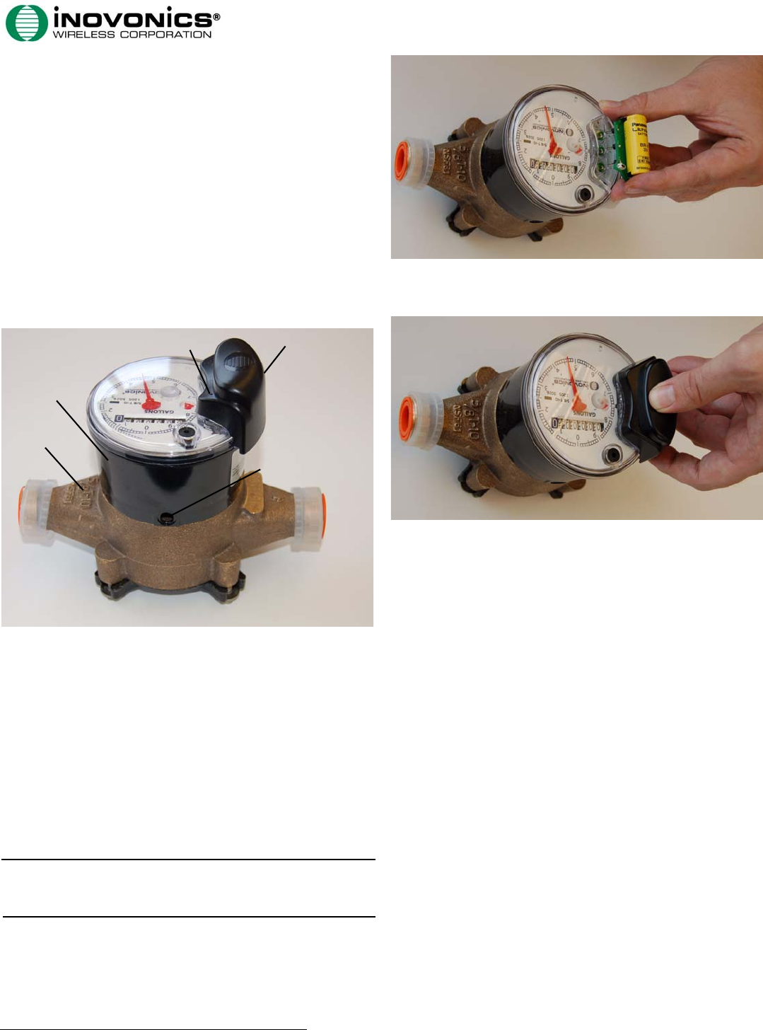
1.2 EN1550 Components
Figure 1 EN1550 Components
2 Installation and Startup
2.1 Install the Power Pack
You must install the power pack for the EN1550 to function.
To install the battery pack:
1. Carefully align the three power pack pins to the three
holes in the top of the register and press down evenly,
keeping the pins perpendicular to the holes.
Caution: Install the power pack carefully. If the pins are
not kept perpendicular with the register during installation,
they may break. Never install the power pack at an angle.
Figure 2 Install the Battery Pack
2. Snap the battery pack enclosure into place over the
battery pack.
Figure 3 Install the Battery Pack Enclosure
2.2 Install the Meter
To install the meter:
1. Flush the service line to remove debris prior to installing
the meter.
2. Install suitable inlet and outlet meter valves and
couplings/setters if they are not already present.
• Inovonics Wireless recommends installing a shut-off
valve before the meter.
• Ensure appropriate space is allowed in the line for the
meter and two couple gaskets. The gap from gasket to
gasket should be 7 1/2 inches.
• Ensure the pipe ends are aligned so that the coupling
and meter threads engage without binding or cross-
threading.
• Make sure to adhere to local plumbing codes and
regulations.
3. Remove the meters thread protectors and spud caps.
• Ensure no debris enters the meter during installation.
4. Place the coupling gaskets inside the coupling nuts and
set the meter in the line.
• For best results, install the meter in the horizontal
position, with the register di l facing upward.
• The direction of the flow marked on the meter must
agree with the direction of water flow.
5. Start the coupling nuts by hand, then use a wrench to
tighten.
• Be careful not to cross-thread the connection.
6. Make sure to support the meter if plumbing it to PVC.
A. Main case B. Register C. Operation
button
D. Power pack E. Security pin
D
B
A
C
E
Page 2 © 2006 Inovonics Wireless - www.inovonicswireless.com
7. Slowly open the valve and run enough water to
dissipate entrained air and flush the line.
8. Check to make sure the meter is indicating flow.
9. Check the meter for leaks.
2.3 Complete Installation
After the meter has been installed:
1. Reset the transmitter. See “Send Reset Message” on
page 2 for instructions.
2. Write down the odometer’s initial meter count for entry
into the TapWatch 2 software.
3. Put the meter in rapid transmit mode. “Set Modes” on
page 2 for instructions.
3 Operation/Maintenance
3.1 Remove the Power Pack
If it is necessary to remove the power pack:
1. Lift the outside edge of the battery pack enclosure away
and up from the register to remove it.
2. Use a flat blade screwdriver to evenly lift the battery
pack away from the register at the points marked LIFT HERE.
Caution: Remove the power pack carefully. If the pins are
not kept perpendicular with the register during removal,
they may break. Never remove the power pack by rocking it
away from the register.
Figure 4 Remove the Battery Pack
3.2 Rotate the Register
If the odometer is difficult to read, the register can be
rotated.
Caution: The register should only be rotated if absolutely
necessary. To rotate the register, you will need to purchase
a new security pin from Inovonics Wireless. The security
pin used in EN1550 is meant for one use only.
1. Use a punch to drive the security pin into the register
(Fig. 1).
2. Turn the register 45 degress and lift it off of the meter.
3. Remove the broken security pin from the bottom of the
register.
4. Replace the register in the desired position.
5. Use your thumb to insert a new security pin.
Note: If you will need to rotate the register again, ensure
there’s appropriate clearance to remove the security pin in
the new position.
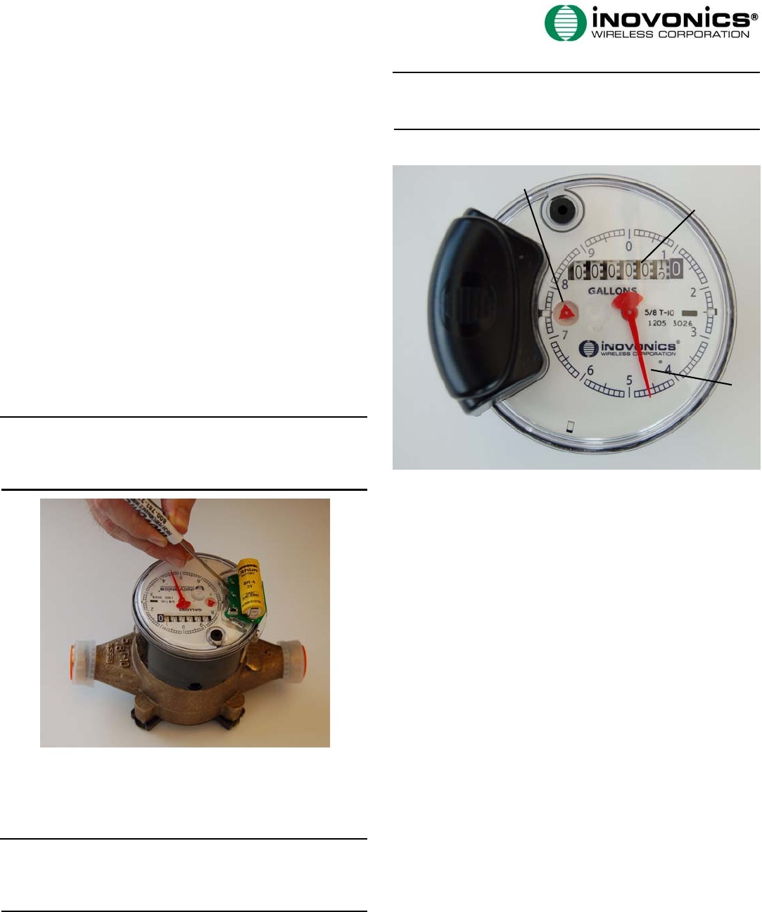
3.3 How to Read the Meter
Figure 5 EN1550 Components
Flow indicator The flow indicator spins when water is
flowing through the meter.
Odometer The odometer displays the number of gallons
used, to the nearest 10 gallons.
Sweep hand The sweep hand indicates the single digit
number of gallons that has passed through the meter. Each
full revolution indicates 10 gallons of consumption, and
will advance the first column on the odometer.
The meter in Figure 5 shows a consumption of 14.6
gallons. The odomoter indicates that 10 gallons have been
used, and the sweep hand adds 4.6 gallons to that
number.
3.4 Send Reset Message
When the EN1550 is reset, the count is zeroed and an RF
reset message is sent. The RF reset message is used for
registration into TapWatch software. To reset the EN1550:
1. Push an unfolded paper clip through the guide hole to
press and hold the Operation button for five seconds
(Figure 2).
3.5 Set Modes
In normal mode, the EN1550 transmits the flow count
approximately once per hour, or upon every 100 gallons of
water, whichever occurs first. When in rapid transmit
mode, the EN1550 transmits the flow count approximately
once per minute. Rapid transmit mode is used during
installation, to help ensure all your programmed end-
devices are functioning correctly.
A. Flow indicator B. Odometer C. Sweep hand
B
A
C
© 2006 Inovonics Wireless - www.inovonicswireless.com Page 3
Once in rapid transmit mode, the EN1550 transmits for
approximately 36 hours, and then returns to normal mode.
The EN1550 can also be returned to normal mode by
resetting it. This will also reset the count to zero.
To set rapid transmit mode:
1. Push an unfolded paper clip through the guide hole to
press the Operation button three times within 10 seconds
(Fig. 1).
2.
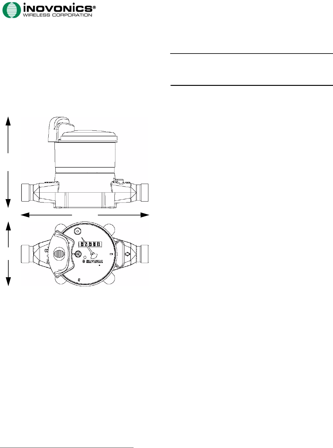
4 Specifications
Meter size: 7.5" x 5.625" x 6.75" (190.5 mm x 142.875
mm x 171.45 mm)
Meter weight: 3.9 lbs (1.769 kg)
Battery type: Panasonic® BR-AG Lithium Cylindrical
battery
Battery life: Guaranteed by Inovonics Wireless for 10 years
Operating environment: 32°- 140°F (0°- 60°C)
Water temperature/pressure: For use with potable cold
water up to 80°F (26.67°C)
Transmitter count: One count for every one US gallon.
Operating frequency: 902-928 MHz.
Thread size: 1” NPSM.
5 FCC Compliance Statement
5.1 FCC ID: HCQ3B6ETIMT
This device complies with part 15 of the FCC rules.
Operation is subject to the following two conditions: (1)
This device may not cause harmful interference, and (2)
this device must accept any interference received,
including interference that may cause undesired operation.
6 Warranty/Disclaimer
Caution: Changes or modifications to this unit not
expressly approved by Inovonics Wireless Corporation may
void the installer's authority to operate the equipment as
well as the product warranty.
Inovonics Wireless Corporation ("Inovonics") warrants its
products ("Product" or "Products") to conform to its own
specifications and to be free of defects in materials and
workmanship under normal use for a period of twenty-four
(24) months from the date of manufacture. Within the
warranty period, Inovonics will repair or replace, at its
option, all or any part of the warranted Product. Inovonics
will not be responsible for dismantling and/or reinstallation
charges. To exercise the warranty, the User ("User",
"Installer" or "Consumer") must work directly through their
authorized distributor who will be given a Return Material
Authorization ("RMA") number by Inovonics. Details of
shipment will be arranged directly through the authorized
distributor.
This warranty is void in cases of improper installation,
misuse, failure to follow installation and operating
instructions, alteration, accident or tampering, and repair
by anyone other than Inovonics.
This warranty is exclusive and expressly in lieu of all other
warranties, obligations or liabilities, whether written, oral,
express, or implied. There is no warranty by Inovonics that
Inovonics product will be merchantable or fit for any
particular purpose, nor is there any other warranty,
expressed or implied, except as such is expressly set forth
herein. In no event shall Inovonics be liable for an
incidental, consequential, indirect, special, or exemplary
damages, including but not limited to loss of profit,
revenue, or contract, loss of use, cost of down time, or
interruption of business, nor any claim made by
distributor's customers or any other person or entity.
This warranty will not be modified or extended. Inovonics
does not authorize any person to act on its behalf to
modify or extend this warranty.
This warranty will apply only to Inovonics Products.
Inovonics will not be liable for any direct, incidental, or
consequential damage or loss whatsoever, caused by the
malfunction of Product due to products, accessories, or
attachments of other manufacturers, including batteries,
used in conjunction with Inovonics Products.
6.75”
5.625”
7.5”