Inovonics Wireless 3B6ETPMT Submetering Transmitter User Manual 04590A
Inovonics Wireless Corporation Submetering Transmitter 04590A
Users Manual
© 2005 Inovonics Wireless - www.inovonicswireless.com
ES1501/EN1501-XL EchoStream
®
TapWatch
®
Transmitter
Installation and Operation Manual - 04590A
1 Overview
Connected to pulse-output meters being used for multi-family
submetering, the ES1501 and EN1501-XL transmitters will
transmit data to an RF receiver that is connected to a Data
Concentrator and Communicator (DCC-5800). The ES1501
includes a replaceable battery; the EN1501-XL includes a long-
life battery that is not replaceable.
1.1 Inovonics Wireless Contact Information
If you have any problems with this procedure, contact Inovonics
Wireless technical services:
• E-mail: support@inovonics.com
• Phone: (800) 782-2709; (303) 939-9336
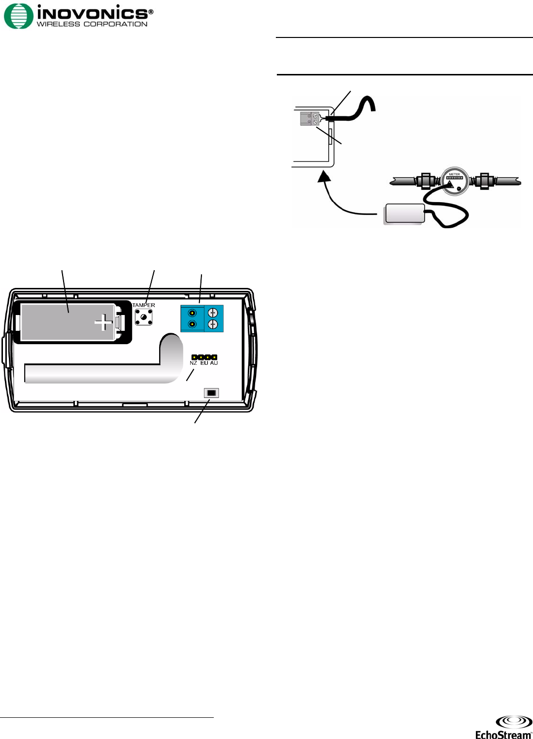
1.2 ES1501/EN1501-XL Components
Figure 1 ES1501/EN1501-XL Components
2 Installation and Startup
2.1 Connect Transmitter to Meter
Connect the transmitter to the meter as follows:
1. Open the housing by pressing down on the base tab near the
wiring thru-hole while lifting away the cover.
2. Fully insert stripped wires into the removable header
terminal.
3. Use a small Phillips screwdriver to tighten the screws that
secure wires to the removable header terminal.
4. Attach removable header terminal (if removed) to the
transmitter board as shown.
Note: If connecting to a meter that has polarity to its pulse
output, the negative (—) should be connected to the outside
terminal, closest to the corner of the board.
Figure 2 Connect the Transmitter to the Meter
2.2 Select Frequency Band
If you are using either transmitter anywhere except North
America, you will need to select the frequency band for your
geographic area. If you are using the transmitter in North
America, there is no need to select the frequency band. All
transmitters are set for North America by default.
Select Frequency Band on the ES1501
1. Place the selection jumper included in the accessory pack on
the appropriate frequency band selection pins (Figure 1).
• Leave the jumper off the pins to select 902-928 MHz for
North America.
• Place the jumper on the left two pins to select 921-928
MHz for New Zealand.
• Place the jumper on the middle two pins to select 868-869
MHz for Europe.
• Place the jumper on the right two pins to select 915-928
MHz for Australia.
Select Frequency Band on the EN1501-XL
1. Place the selection jumper included in the accessory pack on
the appropriate frequency band selection pins (Figure 1).
• Leave the jumper off the pins to select 902-928 MHz for
North America.
• Place the jumper on the left two pins to select 921-928
MHz for New Zealand.
• The selection marked EU is non-functional on the EN1501-
XL. Do not select the middle two pins.
• Place the jumper on the right two pins to select 915-928
MHz for Australia.
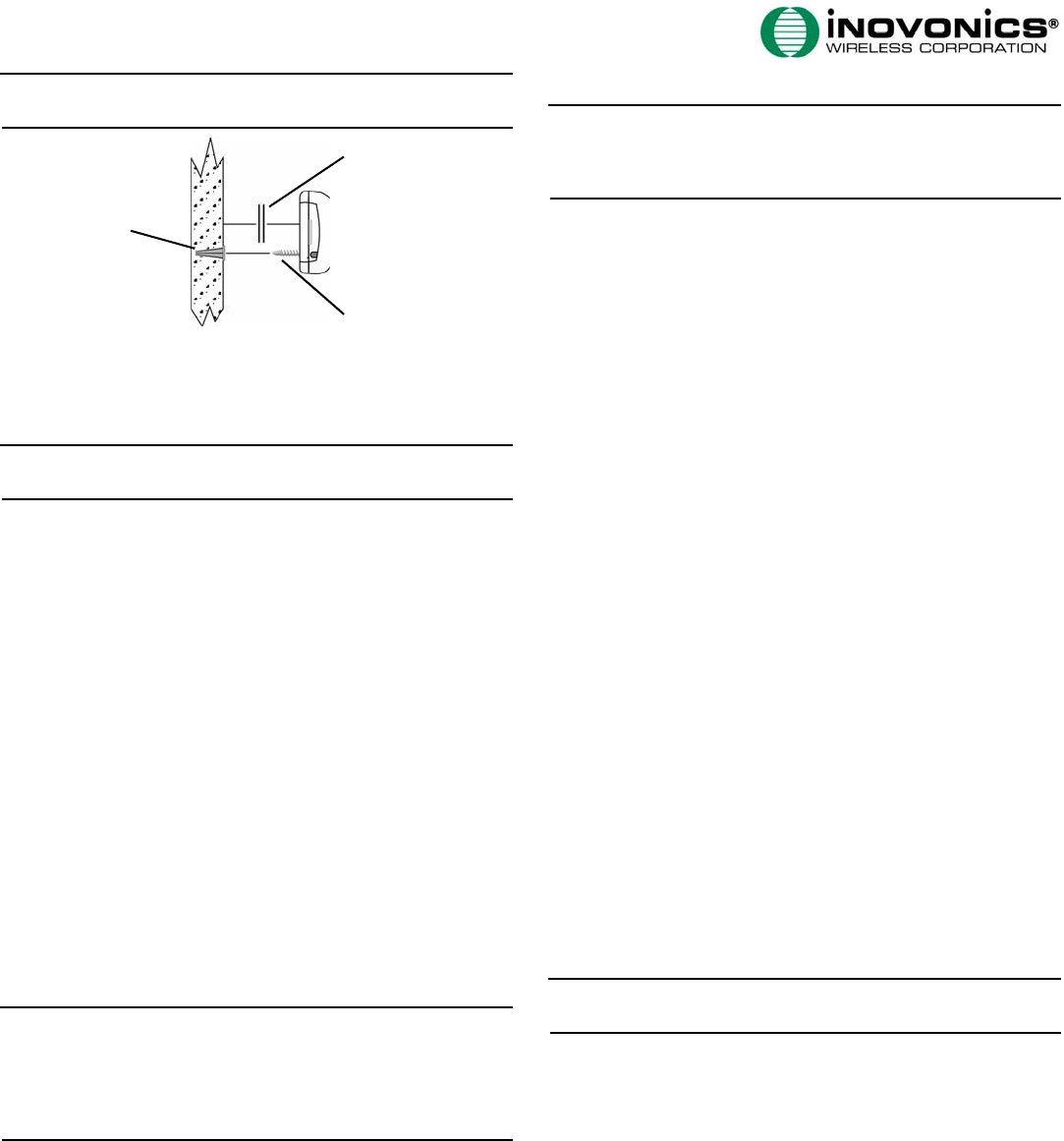
2.3 Mount the Transmitter
1. Use the double-sided tape to mount the transmitter to a clean
wall.
2. If installing the ES1501, the transmitter can be secured a wall
with the mounting screw and anchor. Remove the battery to
access the mounting screw hole; press the reset button after
replacing the battery.
A. Battery (ES1501-
style battery shown)
B. Tamper switch C. Removable header
terminal
D. Frequency band
selection pins
E. Reset button
C
AB
E
D
A. Cabling thru-hole B. Removable header terminal
A
B
Note: Ensure cabling enters the housing through the access
wiring thru-hole, and replace the housing (Figure 2).
Figure 3 Mount the Transmitter
2.4 Register the Transmitter
Note: See “Programming the PMT-Meter Pair” in TapWatch User
Manual for more information.
1. Confirm that transmitter is connected to the meter.
2. Confirm that the battery is installed.
3. Go to the “Registered Meters” tab of the Site Information
editor.
4. Click “Add” on the “Registered Meters” page; confirm selected
building.
5. Complete the “Add New Meter To...” form when it appears.
6. Click the “Register” button.
7. When prompted, press the reset button on the transmitter;
wait for confirmation.
3 Replace the Battery (ES1501 Only)
When the low battery message is received, you will need to
replace the ES1501 battery.
1. Open the housing by pressing down on the base tab near the
wiring thru-hole while lifting away the cover.
2. Remove the old battery, taking note of the battery
orientation.
3. Insert the new battery, making sure it is aligned correctly.
4. Press the reset button.
Note: ES1501 transmitters retain programming data in non-
volatile memory. They do not require reprogramming after loss of
power. Install new battery and press the transmitter reset button
to re-initialize the transmitter and restore programming. Its
count will go to zero and the initial Meter Read count will be
updated in the DCC.
4 Specifications
Dimensions: 3.57" x 1.70" x 0.85"
Operating environment: 0°- 60°C (32°- 140°F), 90% relative
humidity, non-condensing
Typical battery life: ES1501: 5 years at 70 to 90°F (20 to
30°C). Higher temperatures reduce battery life. EN1501-XL:
calculated battery life of 20 years at 70 to 90°F (20 to 30°C).
Higher temperatures reduce battery life.
ES1501 Battery (BAT604): 3.0V lithium (DL123A) The battery
is always supervised.
5 Warranty/Disclaimer
Caution: Changes or modifications to this unit not expressly
approved by Inovonics Wireless Corporation may void the
installer's authority to operate the equipment as well as the
product warranty.
Inovonics Wireless Corporation (“Inovonics”) warrants its
products (“Product” or “Products”) to conform to its own
specifications and to be free of defects in materials and
workmanship under normal use for a period of fourteen (14)
months from the date of manufacture. Within the warranty
period, Inovonics will repair or replace, at its option, all or any
part of the warranted Product. Inovonics will not be responsible
for dismantling and/or reinstallation charges. To exercise the
warranty, the User (“User”, “Installer” or “Consumer”) must work
directly through their authorized distributor who will be given a
Return Material Authorization (“RMA”) number by Inovonics.
Details of shipment will be arranged directly through the
authorized distributor.
This warranty is void in cases of improper installation, misuse,
failure to follow installation and operating instructions,
alteration, accident or tampering, and repair by anyone other
than Inovonics.
This warranty is exclusive and expressly in lieu of all other
warranties, obligations or liabilities, whether written, oral,
express, or implied. There is no warranty by Inovonics that
Inovonics product will be merchantable or fit for any particular
purpose, nor is there any other warranty, expressed or implied,
except as such is expressly set forth herein. In no event shall
Inovonics be liable for an incidental, consequential, indirect,
special, or exemplary damages, including but not limited to loss
of profit, revenue, or contract, loss of use, cost of down time, or
interruption of business, nor any claim made by distributor's
customers or any other person or entity.
This warranty will not be modified or extended. Inovonics does
not authorize any person to act on its behalf to modify or
extend this warranty.
This warranty will apply only to Inovonics Products. Inovonics
will not be liable for any direct, incidental, or consequential
damage or loss whatsoever, caused by the malfunction of
Product due to products, accessories, or attachments of other
manufacturers, including batteries, used in conjunction with
Inovonics Products.
Note: E-mail support@inovonics.com for a copy of the CE
Declaration of Conformity.
A. Anchor installed in wall B. Double-sided tape
C. Mounting screw
A
B
C