Inovonics Wireless 3B6ETVCSM Container Sensor User Manual DS350
Inovonics Wireless Corporation Container Sensor DS350
Users Manual
DS350 Container Sensor
WARNING: Read and understand all instructions and
warnings for this product. In addition, read and follow all
instructions and warnings provided with the DS100 JobSite Security
Portable Alarm System.
CAUTION: DANGER OF EXPLOSION, INJURY, OR FIRE.
Carefully follow all instructions and warnings on the battery label and
package.
• Never use a damaged or worn out battery.
• Discharged batteries should be replaced only with type CR-123 3.0
Volt Lithium batteries.
• Do not use re-chargeable batteries or attempt to charge batteries.
• Carefully remove the old, discharged battery.
• Do not attempt to open.
• Do not peel the label from the battery.
• Never dispose of a battery in a fire.
• Dispose of used batteries in accordance with local regulations.
• Recycle batteries.
• Always insert batteries correctly with regard to polarity (+ and -)
marked on the battery and the equipment.
• When installing the battery, do not use excessive force. If the bat-
tery does not fit, check to make sure that it matches the polarity
markings.
• Never expose the battery terminals to any other metal object. This
can short circuit the battery.
• Avoid exposure to temperature extremes.
• When not in use, store the battery in a cool, dark, dry place.
• Keep batteries out of reach of children.
• This product is designed for indoor/outdoor use.
FCC REGULATORY STATEMENT (FCC: HCQ3B6ETVCSM)
• This device complies with Part 15 of the FCC rules. Operation is
subject to the following two conditions: (1) This device may not
cause harmful interference, and (2) the device must accept any
interference received, including interference that may cause unde-
sired operation.
INDUSTRY CANADA (IC: 2309A-ETVCSM)
•NOTICE: This equipment meets the applicable Industry Canada
Terminal Equipment Technical Specifications. This is confirmed
by the registration number. The abbreviation, IC, before the reg-
istration number signifies that registration was performed based
on a Declaration of Conformity indicating that Industry Canada
technical specifications were met. It does not imply that Industry
Canada approved the equipment.
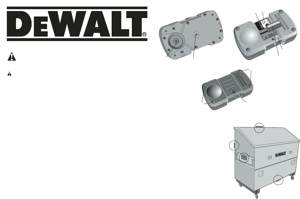
Components (Fig. 1)
A. Sounder D. Sensitivity Adjustment
B. Tampers E. Battery
C. Reset Button F. Captive Screw
Product Function
The DS350 Container Sensor is used for monitoring remote metal
containers by measuring vibration.
Once activated, this device will work exclusively with the assigned
DS100 JobSite Security Portable Alarm System.
1. The DS350 features 900 MHz spread spectrum communication
with the Base Unit allowing for a range of up to 2000' (610 m).
2. The Container Sensor includes user adjustable controls which
allow for sensitivity adjustments to avoid false alarms.
3. A 80db sounder is used for testing sensitivity.
4. The durable housing was designed for mounting the DS350 on
the outside of containers and tough enough to withstand outdoor
conditions.
5. Temporary mounting capabilities with the use of magnets or
permanent mounting by mounting with bolts.
6. Captive screw used to keep the front cover closed.
7. The DS350 Container Sensor uses a CR-123 3.0V Lithium battery
for long life.
8. The DS350 features an inside tamper that notifies the system
when the sensor cover is removed.
9. The DS350 also features an outside tamper that notifies the sys-
tem when the sensor has been removed from the container to
which it was affixed.
10. The reset button allows the Container Sensor to be registered to
any DEWALT JobSite Security system with easy set up.
NOTE: Metal objects blocking radio frequency (RF) transmission can
affect the range of the sensor.
Prevention of False Alarms
The majority of alarms that occur are false. These situations happen
every day due to user error, incorrect installation or improper mainte-
nance of the system. False alarms will limit the responsiveness to the
system, and become a general inconvenience. As the number of
false alarms increases, authorities have become less apt to respond
to alarm systems due to this problem. Many of these situations can be
avoided by following some very simple practices.
• Ensure all users are properly trained on the operation of the
system.
• Always turn off the system with the Key Chain Remote Control
before entering protected area.
• Lock all protected doors, windows or any other asset attached to
a sensor.
• Check that motion detectors are not obstructed. Do not allow
sources of heat or sound in range of the motion or vibration
sensors.
AB
FIG. 1 FIG. 2
SITELOCK LLC, 626 Hanover Pike, Hampstead, MD 21074 (AUG04) Form No. XXXXXX-XX DS350 Copyright © 2004 DEWALT
CAUTION: POTENTIAL EQUIPMENT
MALFUNCTION OR FAILURE. Do not
touch the electronic components inside
the device, except the reset button and
battery.
CAUTION: POTENTIAL EQUIPMENT
MALFUNCTION OR FAILURE. Metal
objects blocking radio frequency (RF)
transmission can affect the range of the
sensor. Place Container Sensor on the
OUTSIDE of a metal container to ensure
transmission of RF signal.
E
CD
F
B
FIG. 3 G
G
SUGGESTED LOCATIONS

• Check that premises are cleared and assets secured before setting
the system.
• Turn off all noise sources – radios, compressors, generators,
heavy equipment, etc.
• Know how to cancel an alarm or turn off the system before
activating.
• If a false alarm is tripped notify customer service immediately.
• Test the system on a monthly basis to ensure proper functioning
• Check cellular signal, power supply, and that sensors are secured
on a daily basis.
Recommended Locations
• Recommended for use on steel containers, large tool boxes, and
tool storage boxes.
• Place on the
OUTSIDE
of a metal container to ensure transmission
of RF signal.
Installing & Changing Battery
The DS350 Container Sensor requires a non-rechargeable CR-123
3.0 Volt Lithium battery.
TO INSTALL A BATTERY
1. Using a Phillips screwdriver, loosen the captive screw (F).
2. Flip open the latch.
3. Install the battery using the polarity (+ and -) markings on the
battery and equipment. Do not use excessive force. If the battery
does not fit, ensure that it matches the polarity markings.
4. Press the Reset Button (C) on the device. After resetting the
sensor (see Device Registration), replace the cover. By open-
ing the device, the Base Unit may display a tamper fault.
TO CLEAR A FAULT
a. Select DISPLAY.
b. Scroll list of fault(s).
c. Select CLEAR.
d. Enter master code.
e. Select OK.
TO CHANGE THE BATTERY
CAUTION: Never use a damaged or worn out battery.
1. Carefully remove the old, discharged battery. Dispose of the bat-
tery according to local regulations.
2. Install new battery using the polarity (+ and -) markings on the bat-
tery and equipment. Do not use excessive force. If the battery
does not fit, ensure that it matches the polarity markings (Fig. 2).
3. Press the Reset Button (C) on the device to re-register the sen-
sor and restore programming. After resetting the sensor, replace
the cover. By opening the device, the Base Unit may display a
tamper fault.
TO CLEAR A FAULT
a. Select DISPLAY.
b. Scroll list of fault(s).
c. Select Clear.
d. Enter master code.
e. Select OK.
Device Registration
To activate the device, it must first be assigned to your DS100 Base
Unit. Refer to the DS100 JobSite Security Portable Alarm System
Instruction Manual for more details on registering a device during the
initial setup.
NOTE: The system must be disarmed prior to any programming
changes.
1. Press the MAIN MENU button on the keypad of the DS100 Base
Unit.
2. Using the keypad, enter the master code.
3. Use the up and down arrows to scroll through the menu until the
System Settings menu is displayed. Select OK.
4. Use the up and down arrows to scroll through the menu until the
Wireless Device Maintenance menu is displayed. Select OK.
5. Use the up and down arrows to scroll through the menu until the
Add/Replace Device screen is displayed. Select OK.
6. The next available device number will be displayed. Up to 48 sen-
sors can be registered to the system. If there are no slots avail-
able, the screen will display ALL DEVICES IN USE. When the
device number is shown, select OK.
7. Using a Phillips screwdriver, remove the captive screw. Flip open
the latch.
8. When prompted by the LCD screen to RESET DEVICE, press
and release the reset button (C) located on the sensitivity keypad
(Fig. 2). The screen will indicate that the device has been regis-
tered.
9. Immediately replace the cover.
10. To edit the description of the device, select EDIT.
11. To edit the description, use the keypad to type a description of up
to 8 characters. The character that is being changed will be under-
lined. To move back a character, use the down arrow key. To move
forward a character, use the up arrow key. When complete, select
SAVE.
IMPORTANT: Write the device description and corresponding
device number on the Sensor Location List included with the
DS100 JobSite Security Portable Alarm System. Keep this sheet
for reference. This information will be needed during the monitoring
service enrollment process. As device changes are made, be sure
to contact DEWALT customer service to make adjustments to the
monitoring service.
12. After registration, test the sensor. If programming through the initial
setup, the test function will be included in the setup sequence.
If adding the Container Sensor after the alarm system has been
programmed, use the TEST button on the keypad.
Adjusting Sensitivity
The sounder will indicate with a ticking noise as the sensitivity is being
increased (less vibration) or decreased (more vibration). When the
maximum and minimum are reached, the sensor will beep. Pressing
the reset button will send the sensitivity to the default (medium).
Walk Test
To activate the Container Sensor walk test, create vibration on the con-
tainer. Adjust the sensitivity as appropriate for the type of container
being secured. The Base Unit will indicate that the test was successful
when the device is removed from the list on the LCD screen.
Mounting
The DS350 can be mounted permanently using four #8 screws, four
bolts or temporarily with the magnets on the back of the container
sensor.
IMPORTANT: Because the Container Sensor uses radio frequency
(RF) which can be blocked by metal objects, do not place the DS350
Container Sensor
INSIDE
the container or storage box.
Align the sensor on the container or storage box in any of the following
locations:
• Underneath the container
• On top of the container
• On the side or back of the container
USING MAGNETS
There are three magnets on the back of the container sensor. These
magnets are used to temporarily attach the sensor on a container or
storage box. If it is removed by an intruder while the system is dis-
armed, the tamper switch will send a signal to the Base Unit. In the
event that the system is armed, an alarm will occur which in turn will
notify the user.
USING BOLTS
In order to permanently attach the sensor on a container or storage
box, use four #8 screws or four bolts as appropriate for the material to
which it is affixed.
1. Use the magnets to hold the DS350 in the desired location.
2. Pre-drill the four locations (G) as marked in Figure 3.
3. Place bolts through each hole.
4. Lock bolts with the appropriate nut. (washer if desired)
Tamper – Faults
Faults indicate when there has been a serious issue that needs to be
addressed. This could be a number of things including an unsecured
device, low battery, tamper or weak signal.
If a fault is present, the system will chime and the Fault screen will be
displayed. To silence the chime, select SILENCE. To display the fault
and resolve immediately, select DISPLAY. Use the up and down

arrows to scroll through the faults. Resolve the issue with the action
listed in Description of Fault Codes chart.
TO REMOVE A TAMPER FAULT
1. Select CLEAR.
2. Use the keypad to enter the master code.
3. Select OK.
Full One Year Warranty
The DEWALT JobSite Security Portable Alarm System is warranted for
one year from date of purchase. We will repair, without charge, any
defects due to faulty materials or workmanship. For warranty repair
information, visit www.dewalt.com or call 1-800-4-DEWALT
(1-800-433-9258). This warranty does not apply to accessories or
damage caused where repairs have been made or attempted by
others. This warranty gives you specific legal rights and you may have
other rights which vary in certain states or provinces.
Fault Code Fault Display Description Action
DevPower Primary Power No battery power Change battery,
Lost Device # in device reset
DevLowBatt Low Battery Device battery Change battery,
Device # low reset
WeakSig Weak Signal Transmission signal Check for interference;
Device # from device is weak move device
Unsecured Unsecured Device has Check for intrusion;
Device # been tripped re-secure device
NoCheckIn No Check In Device check-in Check for interference;
Device # messages have move device
not been received
Tamper Tamper Device has been Close device or
opened or damaged replace if damaged
DESCRIPTION OF FAULT CODES