Inovonics Wireless 3B6IX9NCU Area Control Gateway User Manual 06369B
Inovonics Wireless Corporation Area Control Gateway 06369B
manual
5.8.12 06369B © Inovonics, 2012 - www.inovonics.com
EN6080 Area Control Gateway
Installation Instructions
1 Overview
The Inovonics EN6080 area control gateway bridges the proprietary
Inovonics commercial mesh network to a standard TCP-IP over Ethernet
LAN. Featuring a PSIA-compliant set of RESTful web services, the EN6080
area control gateway is designed to ensure interoperability with other IP-
enabled devices across the security industry.
1.1 Installing an Inovonics Security System
An EchoStream survey kit should be used to establish an EchoStream
system. The EchoStream survey kit measures the signal strength of high-
power repeater and sensor messages to help optimize your EchoStream
system.
Figure 1 Sample EchoStream system
The EchoStream survey kit provides you with two signal strength
measurements: signal level and signal margin.
Signal level
The signal level is the measurement of the overall decibel level of the
message.
Signal margin
The signal margin is the measurement of the decibel level of the message,
minus the decibel level of any interfering signals. Inovonics equipment
should be placed within a facility such that all end-devices produce signal
margin readings of at least 4 decibels.
Both the signal level and signal margin are measured in decibels. Because
signal strength and signal margin are measured on a logarithmic scale, the
difference between a decibel level of 3 (Weak) and a decibel level of 4
(Good) is a much larger difference than it would be on a linear scale.
Note: For more information about the EchoStream survey kit, see the EN/
EE7016SK EchoStream® Survey Kit Installation and Operation Manual.
1.2 Inovonics Wireless Contact Information
If you have any problems with this procedure, contact Inovonics Wireless
technical services:
• E-mail: support@inovonics.com
• Phone: (800) 782-2709; (303) 939-9336
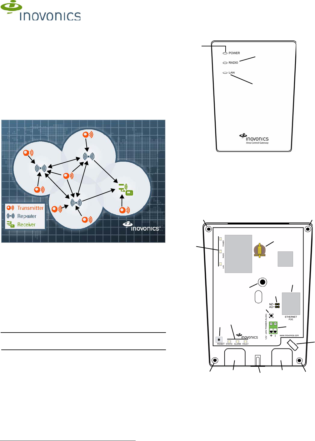
1.3 EN6080 Area Control Gateway Front Panel
Figure 2 EN6080 front panel
Operation LEDs
Power LED: Green indicates the presence of line power or power over
Ethernet.
Radio LED: Green indicates that the device is decoding messages from the
wireless network.
LAN LED: Green indicates Ethernet link.
1.4 EN6080 Area Control Gateway Internal Components
Figure 3 IBEX internal components
APower LED BRadio LED CLAN LED
AWall mount holes BHousing cover release
screw CPower connections
DRJ45 Ethernet jack EOperation LEDs FDiagnostic LEDs
GFrequency band
selection pins HReset button ICabling port
JWall tamper mounting
hole KHousing tamper
switch LCabling tie loop
MBattery holder
A
B
C
AA
AA
B
C
D
G
E
F
H
II
J
K
L
M

5.8.12 06369B © Inovonics, 2012 - www.inovonics.com 2
Diagnostic LEDs
Static LED: Yellow indicates the EN6080 is using a static IP address; green
indicates the EN6080 is using a dynamic IP address obtained from the
network; no illumination indicates the EN6080 has been configured to use
a dynamic IP address but has not obtained one from the network, or there
is no Ethernet connection.
Alarm LED: Red indicates an alarm in the wireless network.
Fault LED: Yellow indicates a tamper, low battery, or repeater line power
loss fault in the wireless network.
1.5 What’s In The Carton
• One 14VAC/120AC transformer
• One CR1220 backup battery
• Five drywall anchors
• Five mounting screws
• One frequency band selection jumper
2 Installation and Startup
2.1 Installation Notes
• These products are designed to be maintained by professional
security technicians
• Products are tested for indoor use
• All products should be manually tested weekly
2.2 Connect Power Cabling And Install Backup Battery
Note: The EN6080 area control gateway is Power over Ethernet capable
on any network supporting the IEEE 802.3af-2003 PoE or IEEE 802.3at-
2009 PoE+ standard. Power over Ethernet will only function when line
power is not present.
To use line power, you will need to connect a power source to the EN6080
area control gateway:
1. Use a Phillips screwdriver to loosen the housing cover release screw
(Figure 3).
2. Lift the cover off the hinges on the top of the housing.
3. Connect power cabling to the Vs and GND connections (Figure 3).
4. Ensuring the polarity corresponds, connect DC power cabling to the +
and - connections; AC power does not require specific polarity and can
use either connection (Figure 3).
• Use 14-22 gauge wire for all cabling and ensure torque on the screw
terminals does not exceed seven inch-pounds.
5. Route the power cabling through the cabling ports on the bottom of the
housing (Figure 3).
6. Connect the power cabling to your power source.
• The power source must be 12-24 VAC or VDC. The power supply
must be unswitched, uninterrupted, and regulated.
7. Insert the backup battery in the battery holder (Figure 3).
2.3 Select the Frequency Band
EchoStream products are able to use a range of radio frequencies, and
must be configured for your geographic area. This product ships with a
default frequency range of 902-928 MHz for use in North America. If you
are using the product in North America, skip to 2.4, “Connect Ethernet
Cabling”; f you are using the product in Australia or New Zealand, you will
need to configure the transmitter.
8. Place a selection jumper on the frequency band selection pins
appropriate to your geographic area (Figure 3).
• Place the jumper on the top two pins, marked NZ, to set the frequency
range to 921-928 MHz for New Zealand
• Place the jumper on the bottom two pins, marked AUS, to set the
frequency range to 915-928 MHz for Australia.
9. Press the reset button to complete configuration (Figure 3).
2.4 Connect Ethernet Cabling
The EN6080 area control gateway connects to network components in a
wired local area network (LAN) using the RJ45 Ethernet jack. To connect to
a LAN:
10. Connect one end of a RJ45 patch cable to the RJ45 Ethernet jack on
the EN6080 area control gateway (Figure 3).
11. Route the Ethernet patch cable through the cabling ports on the bottom
of the housing (Figure 3).
12. Connect the other end of the RJ45 patch cable to an RJ45 Ethernet
jack connected to your LAN.
13. To relieve stress on the Ethernet and power cabling, secure it to the
cabling tie loop with a tie (Figure 3).
2.5 Mount the EN6080 Area Control Gateway
Caution: Mount the EN6080 area control gateway in a location removed
from metal. Metal objects (duct work, wire mesh screens, boxes) will
reduce RF range.
Caution: Per FCC RF exposure requirements, the EN6080 should be
mounted in a location where it will be no more than 100cm from nearby
persons.
The EN6080 area control gateway includes a wall tamper. If the EN6080
area control gateway is removed from the wall, the cutout on the back of
the housing will detach, activating a tamper alarm. The wall tamper will only
work if the EN6080 area control gateway is properly installed. To ensure
the EN6080 is properly installed, carefully follow the mounting instructions:
14. If mounting the EN6080 area control gateway to drywall, install the
drywall anchors included in the installation packet.
Caution: If the EN6080 area control gateway is mounted to drywall, the
drywall anchors must be used. Without the drywall anchors, the back
tamper will not activate if the device is removed from the wall.
15. Use the provided screws to mount the EN6080 area control gateway,
making sure the EN6080 area control gateway is flush with the wall
(Figure 3).
16. Attach the included screw to the wall through the wall tamper mounting
hole (Figure 3).
Caution: Tighten the wall tamper screw to a snug fit without over-tightening
it. Overtightening the wall tamper screw can break the wall tamper cutout,
disabling the wall tamper.
17. Check that the housing tamper spring is in place and makes contact
with the top of the housing (Figure 3).
18. Close the housing.
2.6 Connect to the Ethernet
19. Open a web browser on a computer connected to the same network to
which the EN6080 area control gateway is connected.
20. Direct the browser to the default IP address: 192.168.60.80
21. Navigate to http://www.inovonics.com/area-control-gateway.aspx to
open the EN6080 Area Control Gateway User Manual which will guide
you through setup and configuration.
3 US Patent Numbers
• 7,154,866
• 7,554,932
• 7,746,804
4 Specifications
Compatible repeater, transmitters: EN5040-T, EN1210, EN1210W,
EN1210EOL, EN1212, EN1215, EN1215W, EN1215EOL, EN1215WEOL,
EN1216, EN1223D, EN1223S, EN1224, EN1224-ON, EN1233D,
EN1233S, EN1235D, EN1235DF, EN1235S, EN1235SF, EN1236D,
EN1238D, EN1240, EN1242, EN1247, EN1249, EN1260, EN1261,
EN1261HT, EN1262, EN1265
Dimensions: 5.25x6.75x1.25”
Weight: 12 oz
Interface: 10Base-T Ethernet
Event log size: 1000 alarm events; 1000 fault events
Number of devices suported: 3000
Operating environment: -4°-140°F (-20°-60°C), 90% relative humidity, non-
condensing.
Power requirement: 12-24 VDC/AC; 500mA
Operating frequency: 902-928 MHz, Frequency hopping spread spectrum
Tamper: Type B, fixed device

5.8.12 06369B © Inovonics, 2012 - www.inovonics.com 3
5 Television and Radio Interference
This equipment has been tested and found to comply with the limits for a
Class B digital device, pursuant to Part 15 of the FCC Rules. These limits
are designed to provide reasonable protection against harmful interference
in a residential installation. This equipment generates, uses and can
radiate radio frequency energy and, if not installed and used in accordance
with the instructions, may cause harmful interference to radio
communications. However, there is no guarantee that interference will not
occur in a particular installation. If this equipment does cause harmful
interference to radio or television reception, which can be determined by
turning the equipment off and on, the user is encouraged to try to correct
the interference by one or more of the following measures:
• Reorient or relocate the receiving antenna.
• Increase the separation between the equipment and receiver.
• Connect the equipment into an outlet on a circuit different from that to
which the receiver is connected.
• Consult the dealer or an experienced radio/TV technician for help.
6 FCC Part 15 and Industry Canada Compliance
This device complies with part 15 of the FCC Rules and Industry Canada
license-exempt RSS standard(s). Operation is subject to the following two
conditions: (1) this device may not cause interference, and (2) this device
must accept any interference, including interference that may cause
undesired operation of the device.
Le présent appareil est conforme aux CNR d'Industrie Canada applicables
aux appareils radio exempts de licence. L'exploitation est autorisée aux
deux conditions suivantes : (1) l'appareil ne doit pas produire de brouillage,
et (2) l'utilisateur de l'appareil doit accepter tout brouillage radioélectrique
subi, même si le brouillage est susceptible d'en compromettre le
fonctionnement.
7 Warranty and Disclaimer
Caution: Changes or modifications not expressly approved by the party
responsible for compliance could void the user's authority to operate the
equipment.
Inovonics Wireless Corporation ("Inovonics") warrants its products
("Product" or "Products") to conform to its own specifications and to be free
of defects in materials and workmanship under normal use for a period of
thirty-six (36) months from the date of manufacture. Within the warranty
period, Inovonics will repair or replace, at its option, all or any part of the
warranted Product. Inovonics will not be responsible for dismantling and/or
reinstallation charges. To exercise the warranty, the User ("User", "Installer"
or "Consumer") must work directly through their authorized distributor who
will be given a Return Material Authorization ("RMA") Number by Inovonics.
Details of shipment will be arranged directly through the authorized
distributor.
This warranty is void in cases of improper installation, misuse, failure to
follow installation and operating instructions, alteration, accident or
tampering, and repair by anyone other than Inovonics.
This warranty is exclusive and expressly in lieu of all other warranties,
obligations or liabilities, whether written, oral, express, or implied. There is
no warranty by Inovonics that Inovonics product will be merchantable or fit
for any particular purpose, nor is there any other warranty, expressed or
implied, except as such is expressly set forth herein. In no event shall
Inovonics be liable for an incidental, consequential, indirect, special, or
exemplary damages, including but not limited to loss of profit, revenue or
contract, loss of use, cost of down time, or interruption of business, nor any
claim made by distributor's customers or any other person or entity.
This warranty will not be modified or extended. Inovonics does not
authorize any person to act on its behalf to modify or extend this warranty.
This warranty will apply only to Inovonics Products. Inovonics will not be
liable for any direct, incidental or consequential damage or loss
whatsoever, caused by the malfunction of Product due to products,
accessories, or attachments of other manufacturers, including batteries,
used in conjunction with Inovonics Products.