Inovonics Wireless 3B6OT9ESL Smoke Detector - Transmitter User Manual 05362F
Inovonics Wireless Corporation Smoke Detector - Transmitter 05362F
User's Manual
© Inovonics, 2009 - www.inovonics.com
EN1242 EchoStream® Smoke Detector
Transmitter
Installation Instructions - 05362F
1 Overview
The EN1242 smoke detector is a wireless, battery powered photoelectric
smoke sensor. The sensor includes a built-in sounder for alarm alerts, a
visual status LED, and an Inovonics Wireless EchoStream transmitter. The
sensor works as part of a security/fire alarm system and communicates
with the system control panel. Under normal (non-alarm) conditions, the
LED flashes once every eight seconds while the sensor monitors the
surrounding conditions. When the sensor detects smoke, the LED lights,
the built-in sounder beeps loudly, and an alarm signal is transmitted. The
smoke sensor is powered by the two included three-volt lithium batteries.
When the EN1242 detects an inactive smoke sensor a tamper message
will be transmitted.
Note: For UL installations, refer to the EN4216R Installation and Operation
Manual or the EN7285 Installation Instructions.
1.1 Inovonics Wireless Contact Information
If you have any problems with this procedure, contact Inovonics Wireless
technical services:
• E-mail: support@inovonics.com
• Phone: (800) 782-2709; (303) 939-9336
1.2 EN1242 Components
Figure 1 EN1242 Components
1.3 EN1242 Features
Figure 2 EN1242 Features
2 Installation and Startup
2.1 Install Batteries
1. Turn the sensor housing counterclockwise 15 degrees and detach it
from the mounting base.
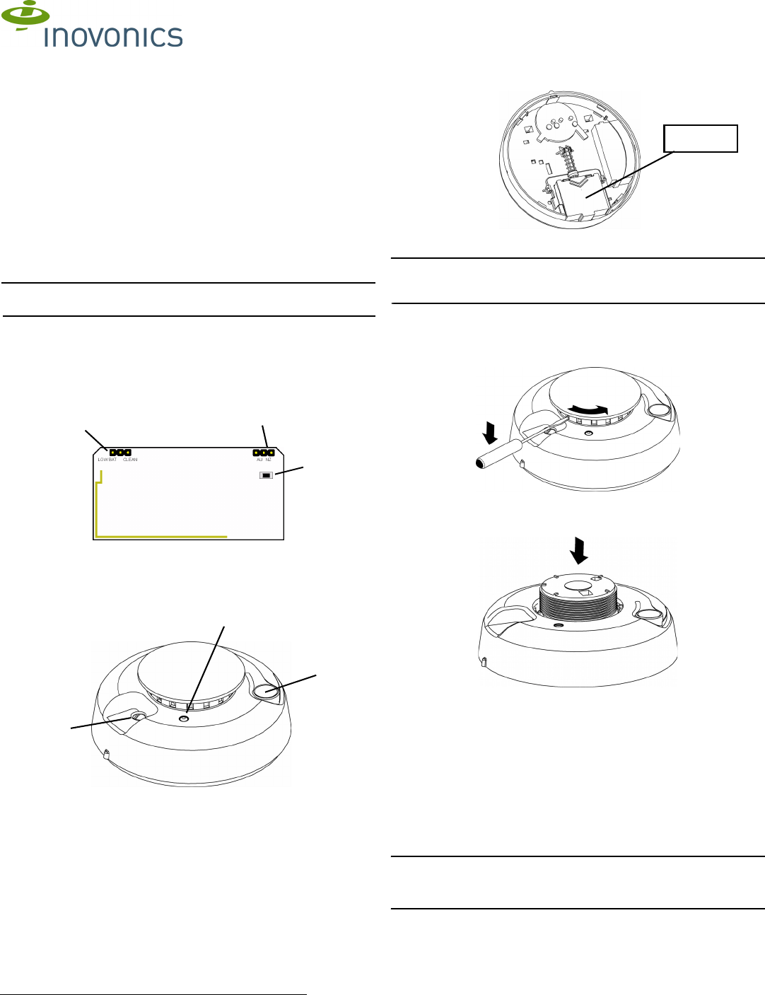
2. Remove the battery compartment cover.
Figure 3 EN1242 Battery Compartment Cover
3. Install/replace the two three-volt batteries.
Note: A tamper message will transmit for approximately ten seconds while
the unit powers up after the installation of both batteries. If only one battery
is installed, the tamper message will transmit continuously.
2.2 Open the Housing
1. Using a small screwdriver to press the sensor cap release tab, apply
downward pressure and turn the cap about one inch counter-clockwise
to remove the cap..
Figure 4 Remove the Sensor Cap
2. Place both thumbs on either side of the optical chamber and push down
to detach the sensor housing.
Figure 5 Push Down on the Optical Chamber
2.3 Select the Frequency Band
EchoStream products are able to use a range of radio frequencies, and
must be configured for your geographic area. To configure the transmitter:
1. Place a selection jumper on the appropriate frequency band selection
pins.
• Place the jumper on the left two pins, marked AU, to set the frequency
range to 915-928 MHz for Australia.
• Place the jumper on the right two pins, marked NZ, to set the
frequency range to 921-928 MHz for New Zealand.
• Leave the jumper off the pins to set the frequency range to 902-928
MHz for North America.
2. Press the Reset button to complete configuration.
Caution: When pressing the Reset button, make sure you don’t also touch
the frequency band selection pins. Touching the frequency band selection
pins while pressing the Reset button can inadvertently set the device to the
wrong frequency band.
ALow Battery/Clean Me
Selection Pins
B Frequency Band
Selection Pins
CReset Button
ASounder Vent BLED CTest/Silence
Button
AB
C
A
C
B
Battery
Compartment

© Inovonics, 2009 - www.inovonics.com 2
2.4 Set CleanMe®/Low Battery Reporting
Set as the factory default, the EN1242 combines the low battery signal with
a signal indicating the detector needs cleaning. If multiple-condition
indication is not desired, wireless reporting of the CleanMe status can be
disabled by moving the jumper on the low battery/CleanMe selection pins
to Low Bat. When this is done, only a low battery signal will be sent from
the detector.
Note: Low battery/CleanMe messages are suppressed when an alarm is
being transmitted.
Note: Even if CleanMe notification is disabled, the sensitivity test will still
indicate sensor condition.
2.5 Register the EN1242
The EN1242 must be registered to function in your EchoStream system.
Refer to your receiver, network coordinator or control panel manual for
registration instructions. Inovonics Wireless recommends all EchoStream
transmitters be supervised. When prompted, you will press the EN1242
Reset button to complete registration.
2.6 Mount the EN1242
1. Use the provided anchors and screws to mount the EN1242, paying
careful consideration to the following best practices:
Caution: Regulations pertaining to smoke sensor installations vary. For
more information, contact your local fire department or local authority
having jurisdiction.
• Install a minimum of two smoke sensors in any household.
• Put a smoke sensor in the hallway outside of every bedroom area.
• Put a smoke sensor on every level of a multi-level residence.
• In rooms with sloped ceilings, install smoke sensors 0.9m (3 feet)
measured down from the highest point of the ceiling.
• Install basement sensors on the ceiling as close to the center of the
room as possible. If this is not practical, install on the ceiling no closer
than 10cm (4 inches) from any wall or corner.
• If ceiling mounting is not practical, install on an inside wall between 10
an 15cm (4 and 6 inches) from the ceiling.
• Put smoke sensors at both ends of a bedroom hallway if the hallway is
more than 9m (30 feet) long. Large rooms over 84 square meters (900
square feet) require more than a single sensor.
• Areas with rough ceilings or short, transom-type walls coming down
from the ceiling require additional smoke sensors.
• Install second-floor smoke sensors on the ceiling at the top of the first-
to-second floor stairwell. Be sure that no door or other obstruction
blocks the path of smoke to the sensor.
Do not locate sensors:
• To a drop ceiling tile; mount it to a metal runner.
• In or near areas such as kitchens or garages, where smoke or vehicle
exhausts normally occur (protect these areas with heat-detection
devices, not with smoke sensors); near furnaces, hot water heaters,
or gas space heaters.
• In damp or very humid areas, or next to bathrooms with showers.
Install sensors at least 1.5m (5 feet) away from bathrooms.
• In very cold or very hot areas.
• In dusty, dirty, or insect infested areas.
• Near fresh air inlets or returns or excessively drafty areas. Air
conditioners, heater, fans, and fresh air intakes and returns can drive
smoke away from smoke sensors.
• In dead air spaces at the top of a peaked ceiling or wall/ ceiling
intersect. Dead air may prevent smoke from reaching a smoke sensor.
• Near fluorescent light fixtures. Install smoke sensors at least 3m (10
feet) away from fluorescent light fixtures.
• Between protruding ceiling structures such as beams or walls which
can create dead air spaces and may prohibit smoke from reaching the
detector.
Caution: All sensors are subject to possible compromise or failure-to-warn
for a variety of reasons. For example: Smoke sensors cannot detect smoke
in chimneys, walls, roofs, or smoke blocked by a closed door; sensors may
not detect smoke on other levels of the building; sensors may not warn in
time when fires are caused by smoking in bed, explosions, improper
storage of flammables, overloaded electrical circuits, or other hazardous
conditions.
3 Test the EN1242
Caution: To avoid a fire department dispatch, contact the central
monitoring station or, if possible, put the system into sensor test mode.
There are two ways to test the EN1242 smoke detector sensor. The
sensitivity test should be performed every week; the smoke test should be
performed at least once a year. Both tests activate the alarm sounder and
send alarm signals.
The EN1242 should also be tested after initial registration, as well as each
time the smoke chamber is changed or the batteries are replaced.
3.1 Smoke Test
Smoke sensors should be tested annually using aerosol simulated smoke,
such as ESL Smoke! In a Can® (ESL Part No. SM-200).
The LED will remain on while the built-in transmitter sends an alarm signal,
and the sensor will produce a three-beep pattern until the Test/Silence
button is pressed. The sensor automatically resets when smoke is no
longer present. A sensor that fails to activate may require cleaning. If a
sensor still fails to activate after cleaning, return the unit for service.
3.2 Sensitivity Test
1. Press and hold the test button for four seconds, then release it. The
LED will flash corresponding to the sensor’s sensitivity.
During this test, the control panel, serial receiver or network coordinator
should receive an alarm and a low battery signal, if low battery is selected,
followed a few seconds later by a restoral.
If the control device fails to respond, it is possible the EN1242 failed to
reset properly when the batteries were installed. To force a reset, remove
the batteries from the EN1242 for a least 30 seconds, reinstall them, press
the Reset button, then retest as described above.
4 EN1242 Operation
4.1 Test/Silence Button
Test/Silence is pressed to perform the sensitivity test, as well as to silence
the low battery chirp. The low battery chirp will resume after 24 hours if the
condition is not corrected.
4.2 Status LED
The LED indicates the status of the sensor as follows:
LED flashing The LED flashes every 8 seconds to indicate normal
operation.
LED on The sensor detects smoke, and is sending an alarm.
LED off Maintenance is required.
4.3 Clean the EN1242
Clean the sensor cover with a dry or damp cloth as needed to keep it free
from dust and dirt. Clean the sensor interior and replace the optical
chamber at least once each year. Use only ESL model 211 optical
chambers for replacement. To clean the sensor chamber:
1. Remove the sensor body from the mounting base.
2. Remove the batteries.
3. Slide a flat-blade screwdriver in the slot on the sensor cap and gently
push the handle down to pry the cap off.
4. Squeeze the optical chamber where indicated and pull it up and away
from the sensor. Discard.
5. Use a soft-bristled brush to remove dust and dirt from the smoke
chamber base.
6. Align the new optical chamber with the base and snap it down into
place.
7. Replace the sensor cap.
8. Reinstall the batteries.
9. Replace the battery cover.
Note: The base will not fit properly if the batteries are not installed.
10. Reattach the sensor to the mounting base.
11. Perform the sensitivity test.
Flashes Sensor Condition/Action
1 Self-diagnostics failure. Return sensor for service/
replacement.
2-3 Sensor is becoming insensitive. Clean the sensor (see
“Clean the EN1242”) and retest. If error persists, replace
sensor.
4-7 Sensor is within normal sensitivity range.
8-9 Sensor is becoming too sensitive. Verify that the smoke
chamber is snapped down securely. Clean the sensor and
retest.

© Inovonics, 2009 - www.inovonics.com 3
5 Specifications
Sensor dimensions: Detector: 14.2cm x 6.1cm (5.4” x 2.4”) Base: 13.7cm
x 1.17cm (5.4 in. x 0.46 in.)
Install temperature: 32°F to 100°F (-0°C to 38°C)
Humidity: 10% to 90% non-condensing
Battery: 2 3V-Lithium batteries. Panasonic CR123A is recommended.
Transmitter frequency range: 900 MHz
Average alarm current: 120mA
Average standby current: 35µA
Typical test current: 2mA Low Battery
Chirp rate: 1 every 45 ± 2 sec.
UL listings: UL 268, UL 985.
6 Warranty/Disclaimer
Caution: Changes or modifications to this unit not expressly approved by
Inovonics Wireless Corporation may void the installer's authority to operate
the equipment as well as the product warranty.
Inovonics Wireless Corporation ("Inovonics") warrants its EchoStream
products ("Product" or "Products") to conform to its own specifications and
to be free of defects in materials and workmanship under normal use for a
period of thirty-six (36) months from the date of manufacture. Within the
warranty period, Inovonics will repair or replace, at its option, all or any part
of the warranted Product. Inovonics will not be responsible for dismantling
and/or reinstallation charges. To exercise the warranty, the User ("User",
"Installer" or "Consumer") must work directly through their authorized
distributor who will be given a Return Material Authorization ("RMA")
number by Inovonics. Details of shipment will be arranged directly through
the authorized distributor.
This warranty is void in cases of improper installation, misuse, failure to
follow installation and operating instructions, alteration, accident or
tampering, and repair by anyone other than Inovonics.
This warranty is exclusive and expressly in lieu of all other warranties,
obligations or liabilities, whether written, oral, express, or implied. There is
no warranty by Inovonics that Inovonics product will be merchantable or fit
for any particular purpose, nor is there any other warranty, expressed or
implied, except as such is expressly set forth herein. In no event shall
Inovonics be liable for an incidental, consequential, indirect, special, or
exemplary damages, including but not limited to loss of profit, revenue, or
contract, loss of use, cost of down time, or interruption of business, nor any
claim made by distributor's customers or any other person or entity.
This warranty will not be modified or extended. Inovonics does not
authorize any person to act on its behalf to modify or extend this warranty.
This warranty will apply only to Inovonics Products. Inovonics will not be
liable for any direct, incidental, or consequential damage or loss
whatsoever, caused by the malfunction of Product due to products,
accessories, or attachments of other manufacturers, including batteries,
used in conjunction with Inovonics Products.