Inovonics Wireless 3B6OT9GSK Wireless Smoke Detector User Manual 06755A
Inovonics Wireless Corporation Wireless Smoke Detector 06755A
User Manual
10.24.16 06755A_v6 © Inovonics, 2016 - www.inovonics.com
EN1244/EN1244-60/EN1244A/EN1244Z
Wireless Smoke Detector
Installation Instructions
1 Overview
The wireless smoke detector features an onboard sounder, a smoke
sensor, an LED indicator and local test capability to allow the user total
visibility of its functionality. It is self-monitoring, alerting the user when
sensor maintenance is needed or batteries are low, and automatically
supervising the radio link.
The EN1244 and EN1244-60 wireless smoke detector have been designed
for operation in the United States; the EN1244A wireless smoke detector
has been designed for operation in Australia; and the EN1244Z wireless
smoke detector has been designed for operation in New Zealand.
The EN1244 wireless smoke detector is intended for open area protection
and for connection to a compatible power supply or control unit for
operation as part of a household fire alarm system (UL985).
Note: For UL 2560 installations, refer to the EN6080 Area Control
Gateway Installation Instructions.
1.1 Maximum Number of Repeaters for a UL 2560
Installation
To achieve the 99.99% alarm message reliability required for UL 2560
compliance, system installations must operate within the following limits for
end device and repeater counts.
1.2 Inovonics Contact Information
If you have any problems with this procedure, contact Inovonics technical
services:
• E-mail: support@inovonics.com.
• Phone: (800) 782-2709; (303) 939-9336.
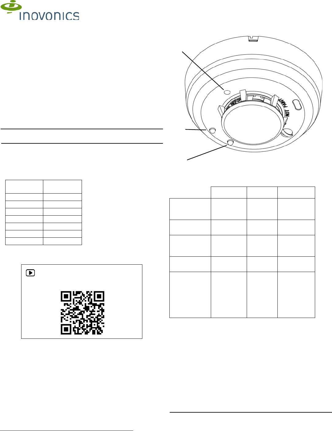
1.3 Wireless Smoke Detector External Components
Figure 1 Wireless smoke detector external components
Device Indicators
1.4 What’s In The Carton
• One 3V-Lithium battery, installed.
• Two drywall anchors.
• Two mounting screws.
2 Installation and Startup
2.1 Installation Notes
• These products are designed to be maintained by professional
security technicians.
• Products are tested for indoor use.
• All products should be manually tested weekly.
2.2 Activate the Battery
1. Remove the orange dust cover.
Note: If the detector cover is loose it can detach while removing the dust
cover. If the detector cover is removed with the orange dust cover, place
End
Devices Maximum
Repeaters
150 397
250 386
350 375
500 360
1000 313
2000 238
3000 184
For product and installation videos visit us at
www.inovonics.com/videos or use the QR
code below.
Green LED Red LED Sounder
Power up Both LEDs
blink every 5
seconds
Both LEDs
blink every
5 seconds
Off
Normal
(standby)
Blinks every
10 seconds
Off Off
Sensitivity out of
range
Off Blinks
every five
seconds
Off
Smoke alarm Off Lit Temporal
pattern
Low battery Off Blinks
every 45
seconds
Chirps every
45 seconds
beginning
seven days
after the LED
begins
blinking
Test
button
Green
LED
Red
LED
10.24.16 06755A_v6 © Inovonics, 2016 - www.inovonics.com 2
the detector cover over the smoke sensor and turn clockwise until it snaps
into place.
2. Twist the detector counterclockwise and lift it off of the mounting base.
3. Remove the plastic tag in the battery compartment to connect the
battery.
4. Ensure the battery is seated.
2.3 Register the Wireless Smoke Detector
The wireless smoke detector must be registered to function in your
EchoStream system. Transmitters must be registered with the system in
order to be monitored and supervised. EN1244, EN1244A and EN1244Z
wireless smoke detectors send a check-in message every three minutes;
EN1244-60 wireless smoke detectors send a check-in message every 60
minutes.
Note: For UL 2560 installations, transmitters must have a minimum check-
in time of 60 minutes.
Refer to your receiver, network coordinator or control panel manual for
registration instructions. Inovonics recommends all EchoStream
transmitters be supervised.
Note: The wireless smoke detector needs twenty seconds to initialize after
power up, during which you will be unable to register devices. During this
initialization period, both LEDs will blink every five seconds.
5. When prompted to register the device, use a small screwdriver or Allen
wrench with a diameter of less than 0.18” to press the recessed test
button (See Figure 1).
2.4 Mount the Wireless Smoke Detector
1. Choose a location for the wireless smoke detector, paying attention to
the following guidelines.
Caution: Regulations pertaining to smoke detector installations vary. For
more information, contact your local fire department or local authority
having jurisdiction.
• Install a minimum of two smoke detectors in any household.
• Put a smoke detector in the hallway outside of every bedroom area.
• Put a smoke detector on every level of a multi-level residence.
• In rooms with sloped ceilings, install smoke detectors 0.9m (3 feet)
measured down from the highest point of the ceiling.
• Install basement detectors on the ceiling as close to the center of the
room as possible. If this is not practical, install on the ceiling no closer
than 10cm (4 inches) from any wall or corner.
• If ceiling mounting is not practical, install on an inside wall between 10
an 15cm (4 and 6 inches) from the ceiling.
• Put smoke detectors at both ends of a bedroom hallway if the hallway
is more than 9m (30 feet) long. Large rooms over 84 square meters
(900 square feet) require more than a single detector.
• Areas with rough ceilings or short, transom-type walls coming down
from the ceiling require additional smoke detectors.
• Install second-floor smoke detectors on the ceiling at the top of the
first-to-second floor stairwell. Be sure that no door or other obstruction
blocks the path of smoke to the detector.
Do not locate detectors:
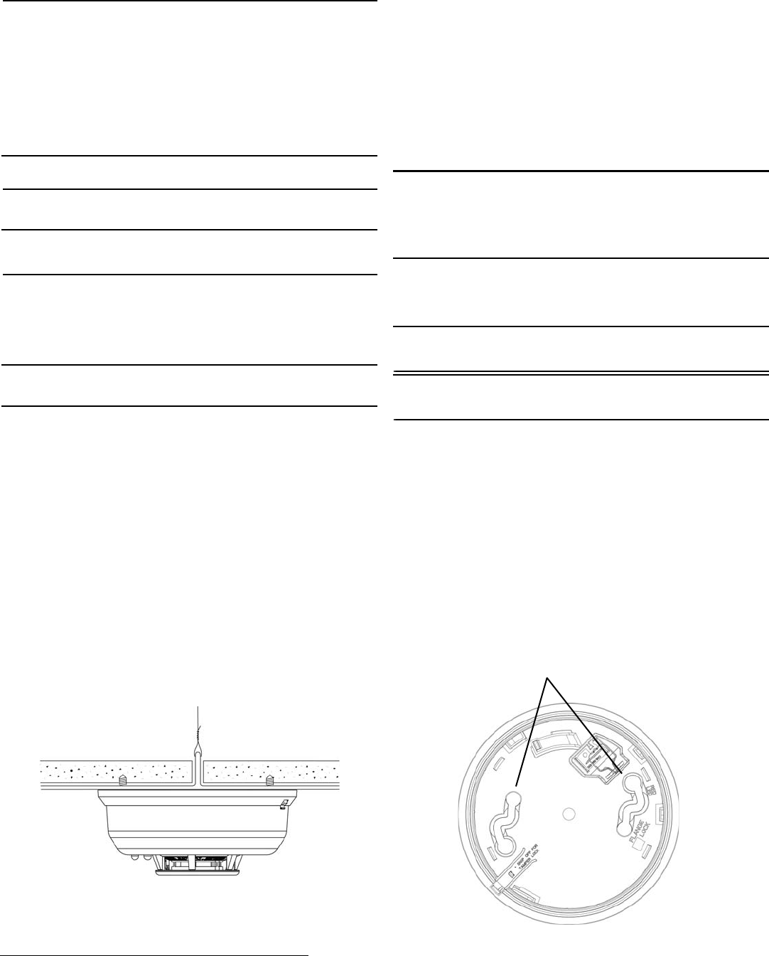
• To a drop ceiling panel; mount it to a metal runner as shown in figure
2.
Figure 2 Mount the smoke detector across drop ceiling panel support
• In or near areas such as kitchens or garages, where smoke or vehicle
exhausts normally occur (protect these areas with heat-detection
devices, not with smoke detectors); near furnaces, hot water heaters,
or gas space heaters.
• In damp or very humid areas, or next to bathrooms with showers.
Install detectors at least 1.5m (5 feet) away from bathrooms.
• In very cold or very hot areas.
• In dusty, dirty, or insect infested areas.
• Near fresh air inlets or returns or excessively drafty areas. Air
conditioners, heater, fans, and fresh air intakes and returns can drive
smoke away from smoke detectors.
• In dead air spaces at the top of a peaked ceiling or wall/ceiling
intersect. Dead air may prevent smoke from reaching a smoke
detector.
• Near fluorescent light fixtures. Install smoke detectors at least 3m (10
feet) away from fluorescent light fixtures.
• Between protruding ceiling structures such as beams or walls which
can create dead air spaces and may prohibit smoke from reaching the
detector.
Caution: All detectors are subject to possible compromise or failure-to-
warn for a variety of reasons. For example: Smoke detectors cannot detect
smoke in chimneys, walls, roofs, or smoke blocked by a closed door;
detectors may not detect smoke on other levels of the building; detectors
may not warn in time when fires are caused by smoking in bed, explosions,
improper storage of flammables, overloaded electrical circuits, or other
hazardous conditions.
Do install:
• Within 10 feet of all sleeping areas.
• On every floor of the building.
• In every room that contains a fuel-burning appliance.
Note: If the room with a fuel-burning appliance is not normally used, such
as a boiler room, the detector should be placed just outside the room so
that the alarm can be more easily heard.
Warning: In order to comply with FCC RF exposure requirements, a 7.87”
(20 cm) distance must be maintained between all persons and the wireless
smoke detector.
Do not install:
• Within 10 feet of any cooking appliance.
• Directly above a sink, cooker, stove or oven.
• Next to a door or window that would be affected by drafts.
• Near an extractor fan or air vent.
• Outside.
• In any environment that does not comply with the detector’s
environmental specifications.
• In or below a cupboard.
• Where air flow would be obstructed by curtains or furniture.
• Where dirt or dust could collect and block the sensor.
• Where the detector could be knocked, damaged, or inadvertently
removed.
2. Referring to figure 3, use the included mounting screws and dry walk
anchors to mount the wireless smoke detector base.
Figure 3 Mounting the wireless smoke detector
Mounting
holes
10.24.16 06755A_v6 © Inovonics, 2016 - www.inovonics.com 3
3. Fit the detector inside the base by aligning it over the base and turning
it in a clockwise direction until it clicks into place.
4. Refer to section 3, “Test the Wireless Smoke Detector” to test the
wireless smoke detector.
3 Test the Wireless Smoke Detector
There are two ways to test the wireless smoke detector sensor. The system
test should be performed every week; the smoke test should be performed
at least once a year.
The wireless smoke detector should also be tested after initial registration,
as well as each time the smoke chamber is cleaned or the batteries are
replaced.
3.1 System Test
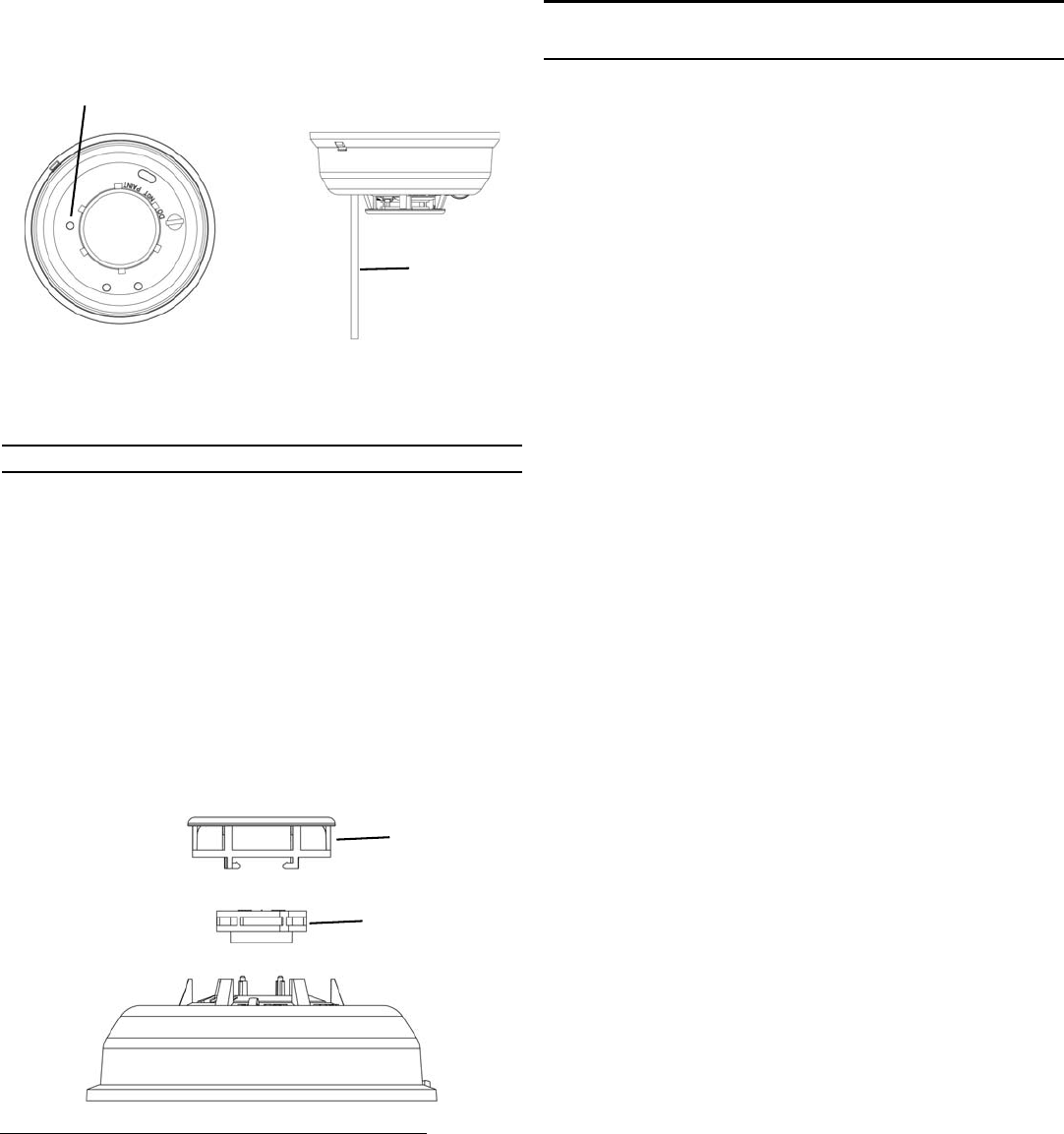
1. Use a small screwdriver or Allen key with maximum diameter of 0.18” to
push and hold the recessed test button for a minimum of five seconds.
Figure 4 Press and hold the recessed test button
2. Ensure the sounder activates, the red LED lights briefly, and the control
panel, serial receiver or network coordinator receives a test signal,
followed a few seconds later by a restoral.
3.2 Smoke Test
Caution: Performing a smoke test will transmit an alarm signal.
1. Use aerosol simulated smoke, such as ESL Smoke! In a Can® (ESL
Part No. SM-200) to perform the smoke test.
• You can also perform a smoke test by holding a smoldering punk stick
or cotton wick at the side of the detector and gently blow smoke
through the detector until it alarms.
2. Ensure the sounder activates, the red LED lights briefly, and the control
panel, serial receiver or network coordinator receives an alarm,
followed a few seconds later by a restoral.
4 Clean the Wireless Smoke Detector
1. Disable the zone or system to prevent any unwanted alarms.
2. Turn the detector counter-clockwise and remove from mounting base.
3. Remove the battery from the unit.
4. To ensure complete power down, wait 20 seconds.
5. Turn the detector cover counter-clockwise and remove.
6. Lift the smoke sensor to remove.
Figure 5 Remove the detector cover and smoke sensor
7. Remove any dust or debris from the detector cover, smoke sensor, and
all other chamber sections using a vacuum or canned air.
8. Align the arrows on the detector cover with the line on the smoke
detector and press down firmly until it is fully seated.
9. Place the detector cover over the smoke sensor and turn clockwise until
it snaps into place.
10. Reinstall the battery, noting proper orientation.
• The red and green LEDs will flash once every five seconds for
approximately 20 seconds until the power-up cycle is complete.
11. Reinstall the detector and test per section 3, “Test the Wireless Smoke
Detector” on page 3.
Caution: If this procedure is not followed, the detector may indicate
maintenance trouble after the power-up sequence is complete. In this case,
remove the battery for 20 seconds and reinstall.
5 Replace the Battery
To replace the battery:
1. Twist the wireless smoke detector counterclockwise and remove it from
the mountain base.
2. Remove the battery, properly disposing of it.
3. To ensure the proper power-down sequence, wait at least 20 seconds
before installing the new battery.
4. Following the polarity diagram inside the battery compartment, install
the new 3-volt CR123A lithium battery.
5. Reinstall the detector onto the mounting base, and turn it clockwise to
lock it into place.
6. Ensure the green LED is blinking about once every 10 seconds to
indicate normal operation.
7. Test the smoke detector as described in section 3, “Test the Wireless
Smoke Detector”.
6 Television and Radio Interference
This equipment has been tested and found to comply with the limits for a
Class B digital device, pursuant to Part 15 of the FCC Rules. These limits
are designed to provide reasonable protection against harmful interference
in a residential installation. This equipment generates, uses and can
radiate radio frequency energy and, if not installed and used in accordance
with the instructions, may cause harmful interference to radio
communications. However, there is no guarantee that interference will not
occur in a particular installation. If this equipment does cause harmful
interference to radio or television reception, which can be determined by
turning the equipment off and on, the user is encouraged to try to correct
the interference by one or more of the following measures:
• Increase the separation between the equipment and receiver.
• Consult the dealer or an experienced radio/TV technician for help.
Changes or modifications not expressly approved by the party responsible
for compliance could void the user's authority to operate the equipment.
7 FCC Part 15 and Industry Canada Compliance
This device complies with part 15 of the FCC Rules and Industry Canada
license-exempt RSS standard(s). Operation is subject to the following two
conditions: (1) this device may not cause interference, and (2) this device
must accept any interference, including interference that may cause
undesired operation of the device.
Le présent appareil est conforme aux CNR d'Industrie Canada applicables
aux appareils radio exempts de licence. L'exploitation est autorisée aux
deux conditions suivantes : (1) l'appareil ne doit pas produire de brouillage,
et (2) l'utilisateur de l'appareil doit accepter tout brouillage radioélectrique
subi, même si le brouillage est susceptible d'en compromettre le
fonctionnement.
Test
button
Press button
with a tool of
0.18” diameter
or less
Detector
cover
Smoke
sensor

10.24.16 06755A_v6 © Inovonics, 2016 - www.inovonics.com 4
8 Specifications
Dimensions: Detector: 5.3” x 2.3”.
Weight: 8.5 oz. without battery.
Operating temperature: 32°F to 120°F (-0°C to 50°C).
Humidity: 0 to 95% non-condensing.
Battery: One 3V-lithium batteries. Panasonic CR123A is recommended.
Average alarm current: 15mA.
Average standby current: 12µA.
Smoke detector sensitivity: 2.0% per ft. obscuration, nominal.
Drift compensation: Automatic.
Compatible receiver for UL 2560 installations with EN1244-60: EN6080.
Compatible repeater for UL 2560 installations with EN1244-60: EN5040-
20T.
Note: The EN1244-60 is a supplemental device that can be installed in a
UL 2560 certified system.
EN1244 complies with: FCC Part 15 rules; RoHS EU Directive 2011/65/EU;
NPFA 72; Industry Canada certification number 2309A-OT9GSK; UL listed
to UL268 and is compatible for usage in a UL985 Household Fire Alarm
System.
Note: Specifications and data are subject to change without notice.
9 US Patent Numbers
• 7,154,866.
• 7,554,932.
• 7,746,804.
• Other patents pending.