Inovonics Wireless 3B6OT9GSKC Wireless CO Detector User Manual 06884D
Inovonics Wireless Corporation Wireless CO Detector 06884D
User Manual Revised
10.16.17 06884D © Inovonics, 2017 - www.inovonics.com
EN1245 Family Wireless CO Detector
Installation Instructions
1 Overview
The wireless CO detector features an onboard sounder, a CO sensor, LED
indicators and local test capability to allow the user total visibility of its
functionality. It is self-monitoring, alerting the user when sensor
maintenance is needed or batteries are low and automatically supervising
the radio link.
The wireless CO detector is available in the following configurations:
The wireless CO detector is intended for open area protection and for
connection to a compatible control unit for operation as part of a household
fire alarm system (UL985).
Note: For UL 2560 installations, refer to the EN6080 Area Control
Gateway Installation Instructions.
1.1 Maximum Number of Repeaters for a UL 2560
Installation
To achieve the 99.99% alarm message reliability required for UL 2560
compliance, system installations must operate within the following limits for
end device and repeater counts.
1.2 Inovonics Contact Information
If you have any problems with this procedure, contact Inovonics technical
services:
• E-mail: support@inovonics.com.
• Phone: (800) 782-2709; (303) 939-9336.
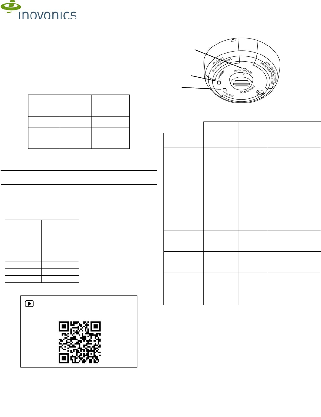
1.3 Wireless CO Detector External Components
Figure 1 Wireless CO detector external components
Device Indicators
1.4 What’s In The Carton
• One 3V-Lithium battery, installed.
• Two drywall anchors.
• Two mounting screws.
2 Installation and Startup
2.1 Installation Notes
• These products are designed to be maintained by professional
security technicians.
• Products are tested for indoor use.
• All products should be manually tested semi-annually.
2.2 Activate the Battery
1. Twist the detector counterclockwise and lift it off of the mounting base.
2. Remove the tag in the battery compartment to connect the battery.
3. Ensure the battery is seated.
Part # Check-In Location
EN1245 3 minutes North America
EN1245-60 60 minutes North America
EN1245A 3 minutes Australia
EN1245Z 3 minutes New Zealand
End
Devices Maximum
Repeaters
150 397
250 386
350 375
500 360
1000 313
2000 238
3000 184
For product and installation videos visit us at
www.inovonics.com/videos or use the QR
code below.
Green LED Red LED Sounder
Normal
(standby)
Blinks every
10 seconds
Off Off
Alarm/test Off Blinks
every one
second
Temporal 4 pattern:
Four short beeps
followed by a five
second pause. If
conditions return to
normal, the detector
self-restores out of
alarm.
Low battery Off Blinks
every 45
seconds for
37 days
Chirps every 45
seconds beginning
seven days after the
LED begins blinking;
continues for 30 days
Detector trouble Off Blinks
every five
seconds
Chirps every 45
seconds
Detector end-of-
life
Off Blinks
every 10
seconds
Chirps every 45
seconds
Power up LED blinks
every ten
seconds for a
total of four
times
LED blinks
every ten
seconds for
a total of
four times
Off
Test
button
Green
LED
Red
LED
10.16.17 06884D © Inovonics, 2017 - www.inovonics.com 2
2.3 Register the Wireless CO Detector
The wireless CO detector must be registered to function in your
EchoStream system. Transmitters must be registered with the system in
order to be monitored and supervised. EN1245, EN1245A and EN1245Z
wireless CO detectors send a check-in message every three minutes;
EN1245-60 wireless CO detectors send a check-in message every 60
minutes.
Note: For UL 2560 installations, transmitters must have a minimum check-
in time of 60 minutes.
Refer to your receiver, network coordinator or control panel manual for
registration instructions. Inovonics recommends all EchoStream
transmitters be supervised.
4. When prompted to register the device, remove and reinstall the battery
per section 6.1, “Replace the Battery” on page 4.
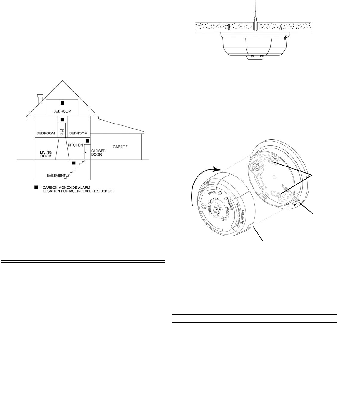
2.4 Mount the Wireless CO Detector.
Figure 2 CO detector placement in multi-level residence
Choose a location for the wireless CO detector, paying attention to the
following guidelines.
Do install:
• Within 10 feet of all sleeping areas.
• On every floor of the building.
• In every room that contains a fuel-burning appliance.
Note: If the room with a fuel-burning appliance is not normally used, such
as a boiler room, the detector should be placed just outside the room so
that the alarm can be more easily heard.
Warning: In order to comply with FCC RF exposure requirements, a 3.94”
(10 cm) distance must be maintained between all persons and the wireless
CO detector.
Do not install:
• Within 10 feet of any cooking appliance.
• Directly above a sink, cooker, stove or oven.
• Next to a door or window that would be affected by drafts.
• Near an extractor fan or air vent.
• Outside.
• In any environment that does not comply with the detector’s
environmental specifications.
• In or below a cupboard.
• Where air flow would be obstructed by curtains or furniture.
• Where dirt or dust could collect and block the sensor.
• Where the detector could be knocked, damaged, or inadvertently
removed.
• To removable ceiling panels. Attach the detector across panel support
as shown in Figure 3.
Figure 3 Mount the CO detector across ceiling panel support
Caution: Airborne dust particles can enter the detector. Inovonics
recommends removing CO detectors before beginning construction or any
other dust-producing activity. Carbon monoxide detectors are not to be
used with detector guards unless the combination has been evaluated and
found suitable for that purpose.
5. Referring to figure 4, use the included mounting screws and dry wall
anchors to mount the wireless CO detector.
6. Referring to figure 4, fit the detector inside the base by aligning it such
that the detector’s alignment notch is slightly offset from mounting
base’s tamper release tab.
7. Turn the detector in a clockwise direction until it clicks into place.
Figure 4 Mounting the wireless CO detector
8. Refer to section 3, “Test the Wireless CO Detector” to test the wireless
CO detector.
3 Test the Wireless CO Detector
There are two ways to test the wireless CO detector sensor: The system
test and CO test. Both tests should be performed at least semi-annually per
NFPA 720.
The wireless CO detector should also be tested after initial registration, as
well as each time the battery is replaced.
Caution: Performing a system or a CO test will transmit an alarm signal.
Turn detector in
counterclockwise
motion.
Alignment
notch
Tamper
release
tab
Mounting
screws
10.16.17 06884D © Inovonics, 2017 - www.inovonics.com 3
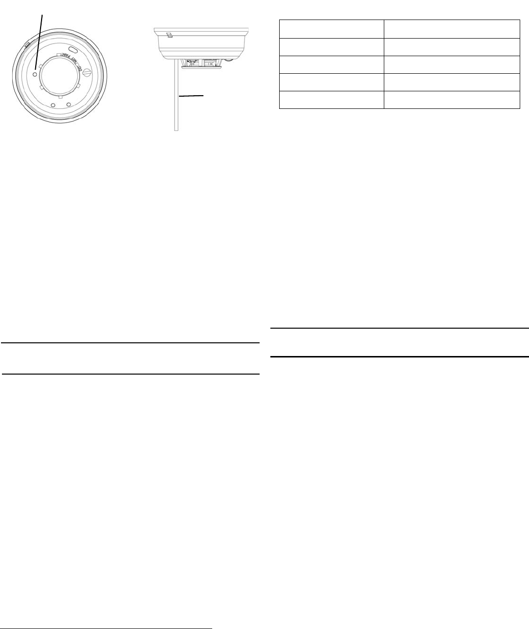
3.1 System Test
1. Use a small screwdriver or Allen key with maximum diameter of 0.18” to
push and hold the recessed test button for a minimum of five seconds
before releasing.
Figure 5 Press and hold the recessed test button
2. Ensure the sounder activates, the red LED lights briefly, and the control
panel, serial receiver or network coordinator receives a test signal,
followed a few seconds later by a restoral.
3.2 CO Test
1. Use a small screwdriver or Allen key with maximum diameter of 0.18” to
push and hold the recessed test button for one to four seconds.
• The green LED should begin to blink rapidly to indicate the CO
detector is in CO test mode.
2. Spray a small amount of CO agent, such as Solo C6 Carbon Monoxide
Detector Tester Aerosol, within 1/4” of the gas entry ports.
3. Ensure the sounder activates, the red LED lights briefly, and the control
panel, serial receiver or network coordinator receives an alarm,
followed a few seconds later by a restoral.
4 Operation
4.1 Carbon Monoxide Gas and Detection
This CO detector is designed for indoor use only. Do not expose it to rain or
moisture. Do not drop the detector or subject it to other physical shock. Do
not open or tamper with the detector as this may cause it to malfunction.
The detector will not protect against the risk of carbon monoxide poisoning
if not properly installed.
Note: The detector will only indicate the presence of carbon monoxide gas
in the vicinity of the detector itself. Carbon monoxide gas may be present in
other areas.
This CO detector is not:
Designed to detect smoke, fire or any gas other than carbon monoxide
• A substitute for the proper servicing of fuel-burning appliances or the
sweeping of chimneys.
• To be used on an intermittent basis, or as a portable alarm for the
spillage of combustion products from fuel-burning appliances or
chimneys.
Carbon monoxide gas is a highly poisonous gas which is released when
fuels are burned. It is invisible, has no smell and is therefore impossible to
detect with the human senses. Under normal conditions in a room where
fuel burning appliances are well maintained and correctly ventilated, the
amount of carbon monoxide released into the room by such appliances
should not be dangerous.
4.2 Symptoms of Carbon Monoxide Poisoning
Carbon monoxide bonds to the hemoglobin in the blood and reduces the
amount of oxygen being circulated in the body. The following symptoms are
related to carbon monoxide poisoning and should be discussed with all
people in the facility:
• Mild exposure: Slight headache, nausea, vomiting, fatigue (often
described as flu-like symptoms).
• Medium exposure: Sever throbbing headache, drowsiness, confusion,
fast heart rate.
• Extreme exposure: Unconsciousness, convulsions, cardio respiratory
failure, death.
Many causes of reported carbon monoxide poisoning indicate that while
victims are aware that they are not well, they become so disoriented that
they are unable to save themselves by either exiting the building or calling
for assistance.
Also, young children and pets may be the first to be affected.
4.3 Alarm Thresholds
Alarm thresholds are as follows:
4.4 In the Case of an Alarm
Actuation of your CO alarm indicates the presence of carbon monoxide
(CO), which can cause injury or death.
Individuals with medical problems may consider using warning devices
which provide audible and visual signals for carbon monoxide
concentrations under 350ppm.
What to do if the carbon monoxide detector goes into alarm:
1. Push the test button. If the detector reactivates or the detector does not
silence, continue with step 2.
2. Immediately move to fresh air, outdoors or by an open window. Check
that all persons are accounted for.
3. Call your local fire department from a phone in an area where the air is
safe. Do not reenter the premises nor move away from the open door/
window until emergency service responders have arrived.
4. If your detector reactivates within a 24-hour period, repeat steps 1
through 3 and call a qualified appliance technician to investigate
possible sources of CO from fuel burning equipment and appliances,
and check for proper operation of this equipment. If problems are
identified during this inspection, have the equipment serviced
immediately. Note any combustion equipment not inspected by the
technician and consult the manufacturer’s instructions, or contact the
manufacturers directly, for more information about CO safety and this
equipment. Make sure that motor vehicles are not, and have not been,
operating in an attached garage or adjacent to the residence.
Caution: This detector should be tested and maintained regularly following
National Fire Protection Association (NFPA) 720 requirements. This
detector should be fully tested at least once per month.
4.5 CO Technology Limitations
The EN1245 uses an electrochemical CO sensing element, and therefore
has certain performance limitations. The CO sensing element has a typical
life of ten years from the date of manufacture, and while the product has a
timer to create a trouble condition after ten years of operating, the date
code of the product, rather than the timer, should determine when the
product is replaced.
The CO sensing element has a carbon filter that provides resistance to
false alarms caused by cross-interference gasses, but the filter can be
saturated, and so the product should not be installed in locations where
high concentrations of these gasses are present. Cross-interference
gasses include, but are not limited to: Methane, Butane, Heptane, Ethyl
Acetate, Isopropyl Alcohol, Carbon Dioxide, Ammonia, Ethanol, Toluene,
Trichloroethane, and Acetone. Only a cloth moistened with water should be
used to clean the EN1245 housing.
The movement of gases into the sensing element can be impaired if a
sealant blocks the porous surface of the CO sensor. The EN1245 should
not be exposed to aerosol products such as furniture polish, paint or
varnish that can coat the CO sensing element and render it inoperative.
5 Maintenance
Occasionally clean the outside casing with a clean water-moistened cloth.
Ensure that the holes on the front of the alarm are not blocked with dirt and
dust. Do not paint, and do not use cleaning agents, bleach, or polish on the
detector.
Test
button
Press button
with a tool of
0.18” diameter
or less
Parts per million Detector response time, min.
30 ± 3ppm No alarm within 30 days
70 ± 5ppm 60-240
150 ± 5ppm 10-50
400 ± 10ppm 4-15

10.16.17 06884D © Inovonics, 2017 - www.inovonics.com 4
6 Detector Replacement
This detector is manufactured with a long-life carbon monoxide sensor.
Over time the sensor will lose sensitivity, and will need to be replaced with
a new carbon monoxide detector. This detector’s lifespan is approximately
ten years from the date of manufacture. The user should periodically check
the detector’s replacement date. Remove the detector from its base and
check the replacement date label on the underside of the detector. The
label indicates the date that the detector should be replaced.
Note: When the detector is removed from its base, a message is sent to
the central station. If the system is armed, a tamper alarm message is sent;
if disarmed, a trouble message is sent. The detector will also indicate a
trouble condition when it has reached the end of its useful life. If this
occurs, it is time to replace the detector.
Note: Before replacing the detector, notify your central station that
maintenance is being performed and the system will be temporarily out of
service. Disable the zone or system undergoing maintenance to prevent
any unwanted alarms. Dispose of detector in accordance with any local
regulations.
Caution: It should be noted that installation, operation, testing and
maintenance of the CO detector is different than smoke detectors. Per
NFPA 720 section 5.3.7.2 the detector shall not be connected to a zone
that signals a fire condition (i.e. smoke detector zones). Therefore, the CO
detector must be programmed as a non-fire zone. See the control panel’s
Installation Instructions for the appropriate carbon monoxide zone type to
be programmed.
6.1 Replace the Battery
Caution: Never install a used or depleted battery, as this can result in
unreliable operation. Only install new batteries.
To replace the battery:
1. Twist the wireless CO detector counterclockwise and remove it from the
mountain base.
2. Remove the battery, properly disposing of it.
3. To ensure the proper power-down sequence, wait at least 20 seconds
before installing the new battery.
4. Following the polarity diagram inside the battery compartment, install
the new 3-volt CR123A lithium battery.
5. Reinstall the detector onto the mounting base, and turn it clockwise to
lock it into place.
6. Ensure the green LED is blinking about once every 10 seconds to
indicate normal operation.
7. Test the CO detector as described in section 3, “Test the Wireless CO
Detector”.
7 Television and Radio Interference
This equipment has been tested and found to comply with the limits for a
Class B digital device, pursuant to Part 15 of the FCC Rules. These limits
are designed to provide reasonable protection against harmful interference
in a residential installation. This equipment generates, uses and can
radiate radio frequency energy and, if not installed and used in accordance
with the instructions, may cause harmful interference to radio
communications. However, there is no guarantee that interference will not
occur in a particular installation. If this equipment does cause harmful
interference to radio or television reception, which can be determined by
turning the equipment off and on, the user is encouraged to try to correct
the interference by one or more of the following measures:
• Increase the separation between the equipment and receiver.
• Consult the dealer or an experienced radio/TV technician for help.
Changes or modifications not expressly approved by the party responsible
for compliance could void the user's authority to operate the equipment.
8 FCC Part 15 and Industry Canada Compliance
This device complies with part 15 of the FCC Rules and Industry Canada
license-exempt RSS standard(s). Operation is subject to the following two
conditions: (1) this device may not cause interference, and (2) this device
must accept any interference, including interference that may cause
undesired operation of the device.
Le présent appareil est conforme aux CNR d'Industrie Canada applicables
aux appareils radio exempts de licence. L'exploitation est autorisée aux
deux conditions suivantes : (1) l'appareil ne doit pas produire de brouillage,
et (2) l'utilisateur de l'appareil doit accepter tout brouillage radioélectrique
subi, même si le brouillage est susceptible d'en compromettre le
fonctionnement.
9 Specifications
Dimensions: Detector: 5.3” x 2.3”.
Weight: 8.5 oz. without battery.
Operating temperature: 32°F to 122°F (-0°C to 50°C).
Humidity: 15% to 95% non-condensing.
Battery: One 3V-lithium batteries. Panasonic CR123A is recommended.
Audible signal (temporal 4 tone): 85 dBA minimum at ten feet when in
alarm.
Compatible receiver for UL 2560 installations with EN1245-60: EN6080.
Compatible repeater for UL 2560 installations with EN1245-60: EN5040-
20T.
Note: The EN1245-60 is a supplemental device that can be installed in a
UL 2560 certified system.
The EN1245 complies with: FCC Part 15 rules; NFPA 720; NFPA 72;
Industry Canada certified; UL Listed to UL 2034 and UL 2075; compatible
for usage in a UL 985 Household Fire Alarm System.
Note: Specifications and data are subject to change without notice.