Inovonics Wireless 3B6OT9OEM EchoStream (ES) System User Manual 06287A
Inovonics Wireless Corporation EchoStream (ES) System 06287A
User Manual
© Inovonics, 2011 - www.inovonics.com
One-Way Binary RF Module
Installation and Operation Manual - 06287A
1 Overview
EchoStream RF modules are designed to be easily interfaced with your electronic
remote application controller (RAC). RF modules allow the assimilation of any user-
specific application into an EchoStream system. Once integrated with existing
products, RF modules provide you with complete EchoStream functionality.
E*1941 one-way binary RF modules are end-devices that use a logic-level connection
to interface with your RAC. E*1941 one-way binary RF modules can be used in either
one-way or two-way EchoStream systems.
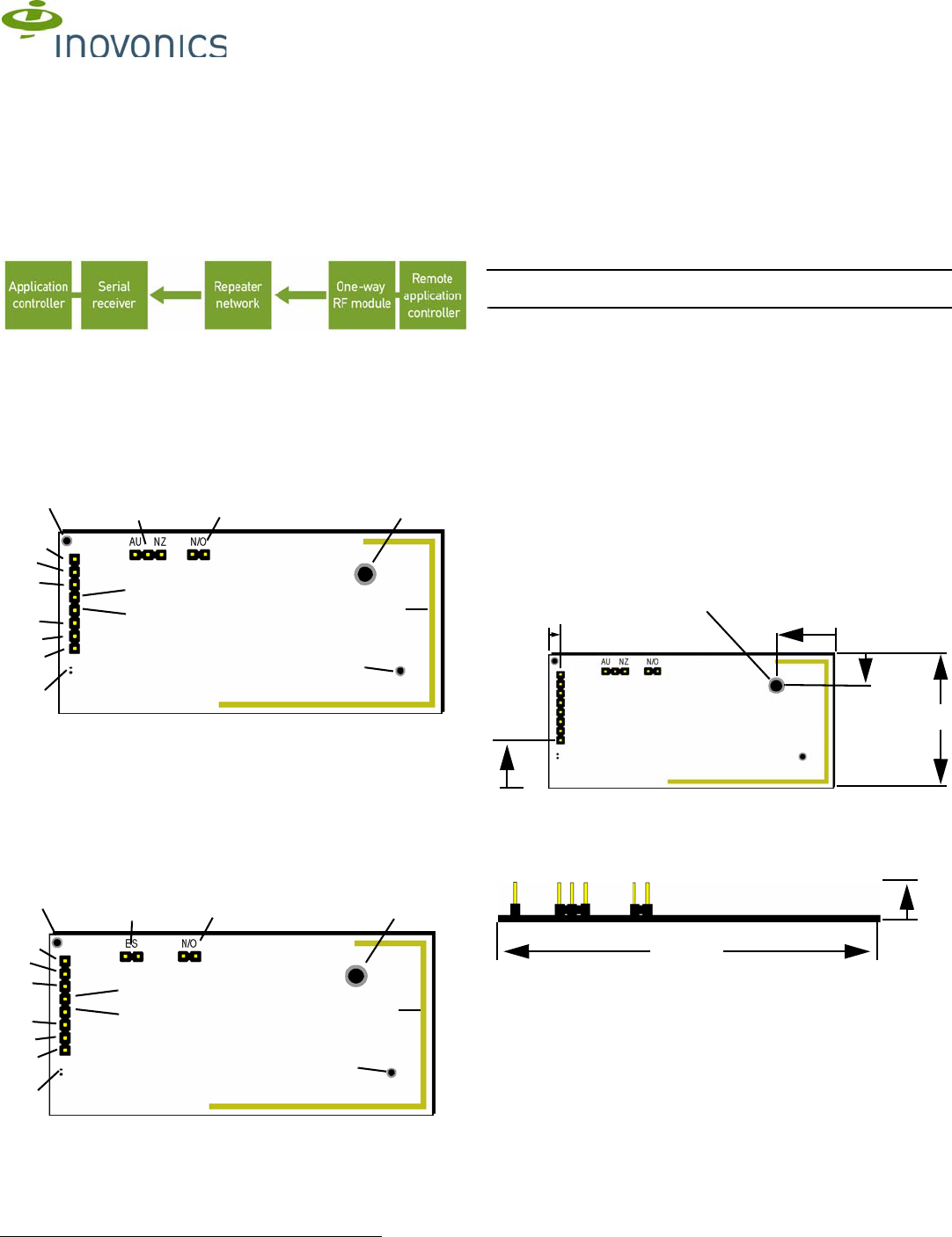
Figure 1 One-Way System Components
2 One-Way Binary RF Module Components
The E*1941 is a universal one-way binary RF module with two alarm input pins,
allowing the use of dual inputs. Input one is the primary alarm, bit 0; input two is the
secondary alarm, bit 1.
There are two models in the E*1941 product family.
• The EN1941, for 900 MHz applications in North America, New Zealand, and
Australia,
• The EE1941, for 868 MHz applications in Europe
Figure 2 EN1941 One-Way Binary RF Module Components
Figure 3 EE1941 One-Way Binary RF Module Components
Frequency band selection pins (EN1941 only) Place a jumper to select the
frequency band for your geographic area.
• Place the jumper on the left two pins to select 915-928 MHz for Australia.
• Place the jumper on the right two pins to select 921-928 MHz for New Zealand.
• Leave the jumper off the pins to select 902-928 MHz for North America.
ES selection pins (EE1941 only) To enable compatibility with ES products, place a
selection jumper on the ES selection pins; if no ES products are used in your system,
remove the selection jumper.
N/O selection pins Place a jumper to select normally open inputs; remove the jumper
to select normally closed.
Note: The E*1941 is shipped with the jumper unattached. With the jumper
unattached, the E*1941 defaults to normally closed.
Secondary alarm Connects a secondary end-device to provide RF alarm data for any
user-specific application.
Primary alarm Connects a primary end-device to provide RF alarm data for any user-
specific application.
Tamper input Connects a tamper input to send a message when user-specific end-
device is tampered with.
Reset input Connects a reset input to reset the one-way binary RF module after a
frequency band selection change or N/O - N/C selection change, and to initiate an RF
transmission.
Power Connect power cabling to an external power supply of 2.4 to 5.5 volts.
Ground Connects to ground.
Mounting hole Used to mount the one-way binary RF module to the user-specific
product. The mounting hole should only be used with a nylon standoff, never metal.
LED contacts Use to control an LED switch. Not designed to drive LED power. See
“LED Requirements” on page 12 for information on using LED contacts.
Board stabilization holes Used to mount and stabilize the board. The board
stabilization holes should only be used with non-metal standoffs.
3 One-Way Binary RF Module Dimensions
Figure 4 E*1941 One-Way Binary RF Module Dimensions
ABoard stabilization hole. BReserved CReserved
DSecondary alarm EPower FGround
GPrimary alarm HLED contacts ITamper input
JReset input KFrequency band
selection pins LN/O selection pins
MMounting hole NOn-board antenna OBoard stabilization
hole
ABoard stabilization hole. BReserved CReserved
DSecondary alarm EPower FGround
GPrimary alarm HLED contacts ITamper input
B
C
G
DI
J
E
F
KLM
N
H
A
O
B
C
G
DI
J
E
F
KLM
N
H
A
O
JReset input KES selection pins LN/O selection pins
MMounting hole NOn-board antenna OBoard stabilization
hole
1.3”
Pitch:
2.54mm.
.385” to
Center of
First Pin
.090” to
Center
of First
Pin .335” to
Center
of Hole
.515” to
Center of
Hole
.156”
Radius
.5”
2.525”
© Inovonics, 2011 - www.inovonics.com 2
4 One-Way Binary RF Module Connections and
Output Jumpers
5 Installation
AConnecting the One-Way Binary RF Module
BOne-way binary RF modules are designed to be easily interfaced with your
electronic remote application controller, however integration must conform to the
following:
CThe RF module must only be connected at the eight pin header or eight pin plated
thru-holes.
DAll cables and wires must be routed away from the component side of the RF
module.
EThe integrated antenna must not be tampered with; no connection to an alternate
antenna is provided.
FThe application module must not include an integrated secondary colocated radio
module.
GThe one-way binary RF module antenna should be placed so that it is facing away,
or otherwise isolated from, your device’s ground plane.
HComponents that are sensitive to RF transmission, such as high gain circuits,
should be isolated from the antenna to prevent interference.
IOne-way binary RF modules should not be mounted on metal surfaces or inside
metal enclosures. They should also not be mounted where sheet metal ductwork,
wire mesh screens, etc. might block transmissions.
JThe RF module should be integrated so the antenna is unobstructed by the end
user’s PCB, batteries, or any other conductive material.
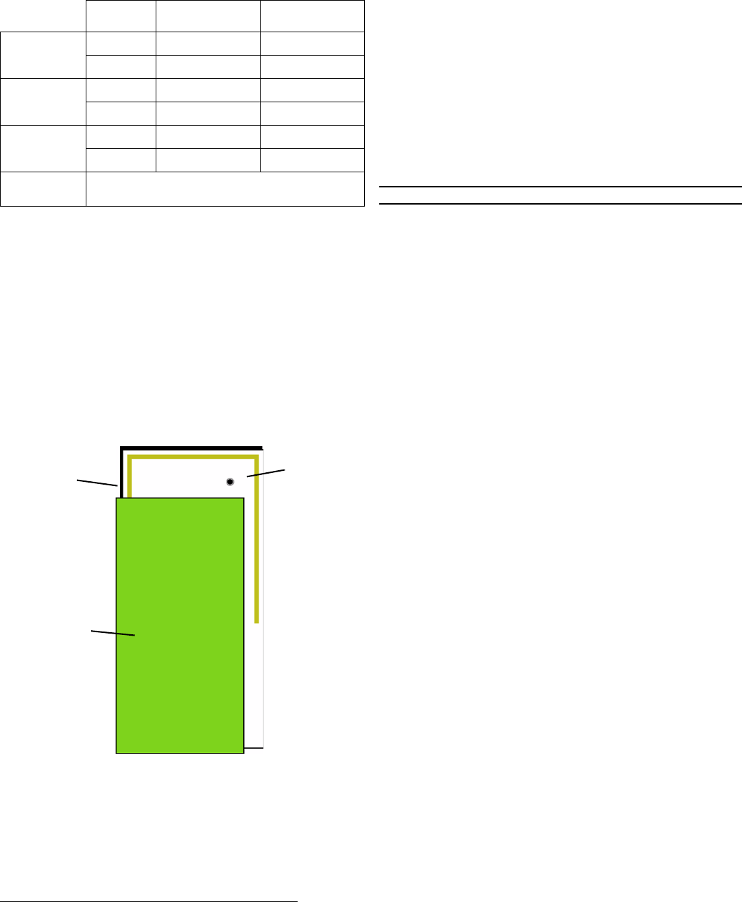
Figure 5 The RF module should be integrated so the antenna is unobstructed
6 One-Way Binary RF Module Requirements
6.1 Power Requirements
The E*1941 has an on-board voltage regulator. Connect power cabling to an external
power supply (Vcc) of 2.4 to 5.5 volts. Voltage must be sustained at 2.4 volts or above
and supply 100 milliamps during the transmit cycle.
6.2 EN1941
Assuming check-in messages every 3 minutes and infrequent alarm messages (one
per day, on average), the average current draw is 32 uA. Peak current draw while
transmitting is less than 100 mA. One alarm/restore cycle per hour results in about 5.3
uA increase in average current.
6.3 EE1941
Assuming check-in messages every 12 minutes and infrequent alarm messages (one
per day, on average), the average current draw is 15 uA. Peak current draw while
transmitting is less than 50 mA. One alarm/restore cycle per hour results in about 5.3
uA increase in average current.
6.4 Low Battery Condition
The E*1941 measures battery voltage every three and a half hours, and, when the
battery measures 2.4 volts, a serial message is sent indicating a low battery condition.
6.5 Temperature range
-20°C to +60°C, non-condensing
6.6 RF network compatibility
EchoStream Commercial Mesh Network
6.7 Input Requirements
Caution: Input levels must not exceed 3.3 V.
Open When an active source (open collector or dry contact) is used to drive the alarm
or tamper input, the voltage should be between 0.75xVcc and Vcc. A passive input
should have an impedance of greater than 5.1k ohm between the input and ground.
Closed When an active source is used, the voltage should be less than 0.25xVcc. A
passive input should have an impedance of less than 240 ohm.
6.8 LED Requirements
The LED output is an active output from the microprocessor, with a 1k series resistor
to limit current draw. Default state is low, and the LED pin is pulled high during
transmit.
7 Compliance Requirements
7.1 FCC Requirements for the EN1941
The EN1941 one-way binary RF module has received a Limited Modular Grant,
requiring Inovonics to retain control of the final installation to ensure compliance to
FCC/IC regulations. The integrator is responsible to test the final installation to verify
compliance to FCC/IC regulation for unintentional emissions.
Prior to marketing the product, the integrator must complete and submit to Inovonics a
compliance review form and documentation, and, if requested, a functional product
sample for approval. If this is not possible, the integrator must perform the testing
themselves and submit proof to Inovonics of compliance to Part 15 of the FCC Rules
and Industry Canada RSS-210.
At the end of this guide is an Inovonics compliance review form to be filled out by the
integrator.
The integrator is also responsible for properly labeling the product containing the one-
way binary RF module. Labels must be placed on the outside of the product, and must
include a statement indicating that the product contains the module, along with the
FCC and IC number.
Example 1 “Contains One-Way Binary RF Module
FCC ID: HCQ3B6OT9OEM; IC ID: 2309A-ETOEMM”
Example 2 “Contains FCC ID: HCQ3B6OT9OEM; IC ID: 2309A-ETOEMM”
7.2 Television and Radio Interference
This equipment has been tested and found to comply with the limits for a Class B
digital device, pursuant to Part 15 of the FCC Rules. These limits are designed to
provide reasonable protection against harmful interference in a residential installation.
This equipment generates, uses and can radiate radio frequency energy and, if not
installed and used in accordance with the instructions, may cause harmful
interference to radio communications. However, there is no guarantee that
interference will not occur in a particular installation. If this equipment does cause
harmful interference to radio or television reception, which can be determined by
turning the equipment off and on, the user is encouraged to try to correct the
interference by one or more of the following measures:
• Reorient or relocate the receiving antenna.
• Increase the separation between the equipment and receiver.
• Connect the equipment into an outlet on a circuit different from that to which the
receiver is connected.
• Consult the dealer or an experienced radio/TV technician for help.
7.3 FCC Part 15 Compliance
This device complies with part 15 of the FCC Rules. Operation is subject to the
following two conditions:
1. This device may not cause harmful interference, and
2. this device must accept any interference received, including interference that may
cause undesired operation.
7.4 CE Label Requirements for EE1941
Inovonics Wireless has received European Telecommunications Standards Institute
approval to market one-way binary RF modules, and they are manufactured to be
RoHS compliant. The integrator is responsible for properly labeling the product
containing the one-way binary RF module. Labels must be placed on the outside of
the product, and must include the CE logo.
Connection Output Jumper N/O Output Jumper N/C
Primary Alarm Open Alarm Clear Alarm
Ground Alarm Alarm Clear
Secondary
Alarm
Open Alarm Clear Alarm
Ground Alarm Alarm Clear
Tamper Open Alarm Alarm
Ground Alarm Clear Alarm Clear
Reset Open for normal operation; connect to the ground and release
for a board reset.
End user
application
printed circuit
board
RF
module
Clear transmit
region in front
and back of
antenna

© Inovonics, 2011 - www.inovonics.com 3
8 Warranty and Disclaimer
Note: Changes or modifications not expressly approved by the party responsible for
compliance could void the user's authority to operate the equipment.
Inovonics Wireless Corporation ("Inovonics") warrants its EchoStream products
("Product" or "Products") to conform to its own specifications and to be free of defects
in materials and workmanship under normal use for a period of thirty-six (36) months
from the date of manufacture. Within the warranty period, Inovonics will repair or
replace, at its option, all or any part of the warranted Product. Inovonics will not be
responsible for dismantling and/or reinstallation charges. To exercise the warranty, the
User ("User", "Installer" or "Consumer") must work directly through their authorized
distributor who will be given a Return Material Authorization ("RMA") number by
Inovonics. Details of shipment will be arranged directly through the authorized
distributor.
This warranty is void in cases of improper installation, misuse, failure to follow
installation and operating instructions, alteration, accident or tampering, and repair by
anyone other than Inovonics.
This warranty is exclusive and expressly in lieu of all other warranties, obligations or
liabilities, whether written, oral, express, or implied. There is no warranty by Inovonics
that Inovonics product will be merchantable or fit for any particular purpose, nor is
there any other warranty, expressed or implied, except as such is expressly set forth
herein. In no event shall Inovonics be liable for an incidental, consequential, indirect,
special, or exemplary damages, including but not limited to loss of profit, revenue, or
contract, loss of use, cost of down time, or interruption of business, nor any claim
made by distributor's customers or any other person or entity.
This warranty will not be modified or extended. Inovonics does not authorize any
person to act on its behalf to modify or extend this warranty.
This warranty will apply only to Inovonics Products. Inovonics will not be liable for any
direct, incidental, or consequential damage or loss whatsoever, caused by the
malfunction of Product due to products, accessories, or attachments of other
manufacturers, including batteries, used in conjunction with Inovonics Products.

© Inovonics, 2011 - www.inovonics.com 4
Inovonics One-Way Binary RF Module Compliance
Review Form
Please provide the following information for review of final installation to
ensure compliance with FCC/IC regulations:
Required materials from integrator
The following must also be attached for review with this form:
• A description of the final installation, with attached photographs, as
necessary
• The unintentional radiator test report indicating compliance
Integrator information
Inovonics contact information
Inovonics
ATTN: Product Management
315 CTC Blvd.
Louisville, CO 80027
Phone: 303.939.9336
Toll-Free: 800.782.2709
Fax: 303.939.8977
productmanagers@inovonics.com
First name: Last name:
Phone number: Email address:
Address:
Declaration of conformity to Inovonics’ installation instructions:
Submitted materials:
Authorized signature: Submission date:

© Inovonics, 2011 - www.inovonics.com 5
Required materials from Inovonics
• The record of product sample review and test, as necessary
Inovonics approval
First name: Last name:
Phone number: Email address:
Approval status (pass, fail, samples required, compliance testing required, compliance test report
required):
Approval comments:
Submitted materials:
Returned materials:
Authorized signature: Approval date: