Inovonics Wireless 3B6OT9RTX Pendant Transmitter User Manual 05596E
Inovonics Wireless Corporation Pendant Transmitter 05596E
Users Manual Revised 04 2014
4/11/14 05596E_v1 © Inovonics, 2014 - www.inovonics.com
EchoStream® EN1233S/D and EN1235S/D
Pendant Transmitter
Installation Instructions
1 Overview
1.1 Inovonics Wireless Contact Information
If you have any problems with this procedure, contact Inovonics
Wireless technical services:
• E-mail: support@inovonics.com
• Phone: (800) 782-2709
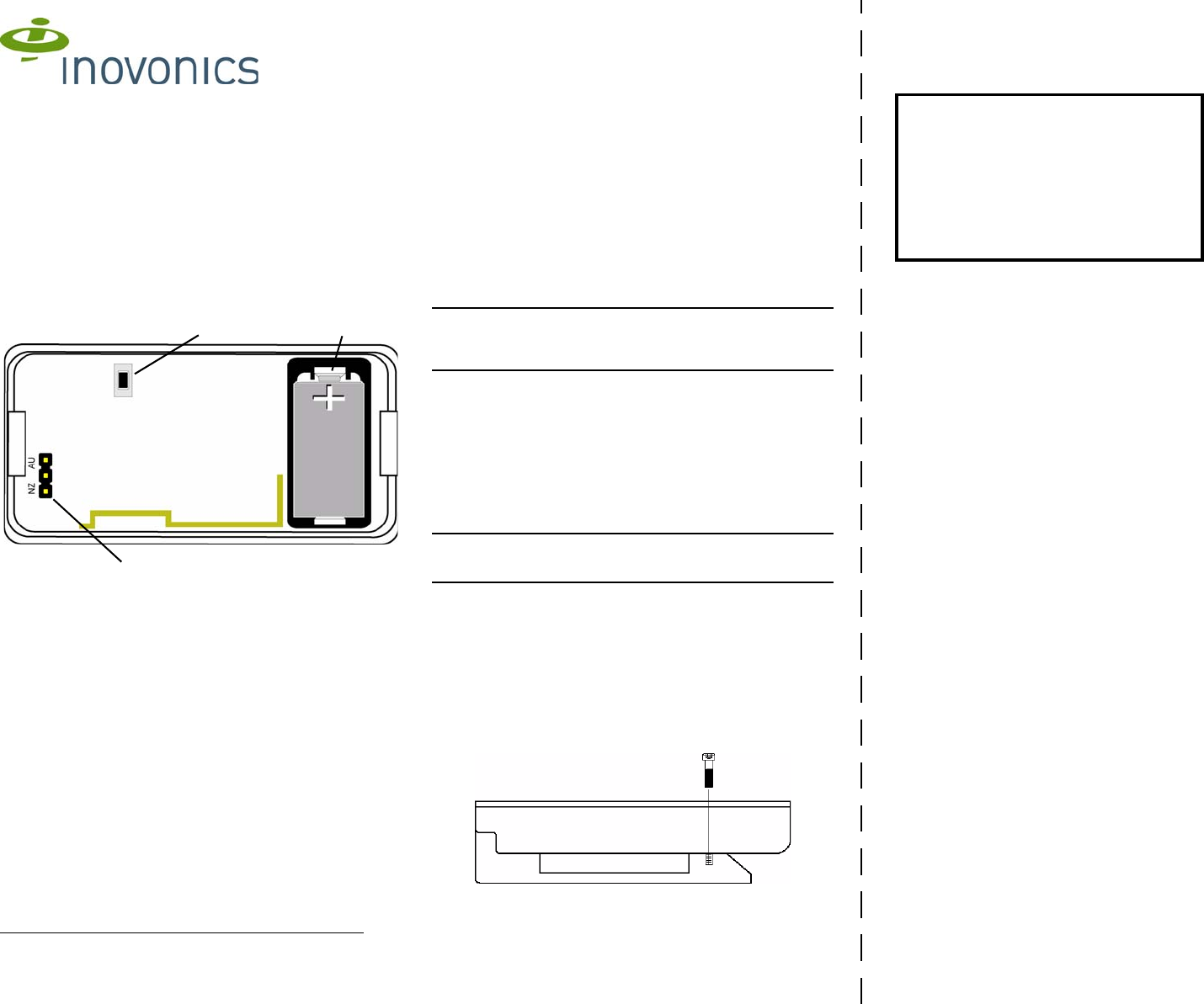
1.2 Pendant Transmitter Components
Figure 1 Pendant Transmitter components
1.3 What’s In The Carton
Individually-packaged products include the following items:
• One belt loop screw
• One selection jumper
• One 3.0V lithium battery
2 Installation and Startup
2.1 Installation Notes
• These products are designed to be maintained by professional
security technicians
• Products are intended for indoor use
• All products should be manually tested weekly (see “Test the
Transmitter” on page 2)
2.2 Initial Setup
Install the Battery
1. Pry the housing apart at either end and pull the two halves
apart.
2. Install the battery.
Select the Frequency Band
EchoStream products are able to use a range of radio frequencies,
and must be configured for your geographic area. This product
ships with a default frequency range of 902-928 MHz for use in
North America. If you are using the product in North America, skip
to “Register the Pendant Transmitter”. If you are using the product
in Australia or New Zealand, you will need to configure the
transmitter.
3. Place a selection jumper on the appropriate frequency band
selection pins.
• Place the jumper on the bottom pins, marked NZ, to set the
frequency range to 921-928 MHz for New Zealand.
• Place the jumper on the top two pins, marked AU, to set the
frequency range to 915-928 MHz for Australia.
4. Press the reset button to complete configuration.
Caution: When pressing the reset button, make sure you don’t also
touch the frequency band selection pins. Touching the frequency
band selection pins while pressing the reset button can
inadvertently set the pendant to the wrong frequency band.
Register the Pendant Transmitter
The pendant transmitter must be registered with the system in order
to be monitored and supervised. When supervised, the pendant
transmitter will send a check-in message to the serial receiver or
network coordinator every three minutes.
Each pendant has a unique factory-programmed identification
number. Refer to the control panel’s installation instructions for
details on registering a transmitter.
5. When prompted by the receiver to reset transmitter, press the
reset button.
6. Replace the cover.
Caution: The pendant should be tested after registration to ensure
operation. To test the pendant, activate each of the conditions and
ensure an appropriate response.
3 Operation
3.1 Using The EN1233 Pendant Chain
Always use the chain included with the ES1233. Substituting
stronger cords or chains may result in injury to the wearer.
3.2 Converting the Pendant Transmitter Belt Clip
If you’d like to convert the pendant transmitter belt clip to a belt loop,
secure the bottom of the belt clip to the housing with a coarse
thread screw.
Figure 2 Use a coarse thread screw to secure the belt clip
AReset button BFrequency band selection pins
CBattery
B
AC
Printing Instructions
1. Print duplex
2. Align and orient back page to match front
page.
3. Cut on dashed line
4. Fold cutsheet in half along the 8.5" axis.

4/11/14 05596E_v1 © Inovonics, 2014 - www.inovonics.com
3.3 Operate the Pendant Transmitter
To activate single button transmitters, press the button for at least
one second. To activate double button transmitters, press both
buttons simultaneously. Alarm signals are transmitted multiple times
and are indicated by the blinking transmission LED. When the
buttons are released, the transmitter sends an alarm restoral
signal.To test a transmitter, activate the alarm by pressing the
button(s).
3.4 Battery Replacement
Replacement batteries can be purchased from Inovonics using the
following part numbers:
• BAT608 for a single battery
To replace the battery:
1. Pry the housing apart at either end and pull the two halves
apart.
2. Install the battery.
3. Press the reset button to initialize the transmitter.
4 Test the Transmitter
The transmitter should be tested weekly and after registration to
ensure operation.
To test the transmitter:
1. Activate the transmitter and ensure the transmit LED lights and
the alarm is received by the receiver or gateway.
2. Press the reset button and ensure the transmit LED lights.
5 Specifications
Typical battery life: 3-5 years
Battery type (BAT608): Panasonic CR2 or equivalent
Operating environment: 0 to 60°C (32 to 140°F), noncondensing
Note: Specifications and data are subject to change without notice.
6 Television and Radio Interference
This equipment has been tested and found to comply with the limits
for a Class B digital device, pursuant to Part 15 of the FCC Rules.
These limits are designed to provide reasonable protection against
harmful interference in a residential installation. This equipment
generates, uses and can radiate radio frequency energy and, if not
installed and used in accordance with the instructions, may cause
harmful interference to radio communications. However, there is no
guarantee that interference will not occur in a particular installation.
If this equipment does cause harmful interference to radio or
television reception, which can be determined by turning the
equipment off and on, the user is encouraged to try to correct the
interference by one or more of the following measures:
• Reorient or relocate the receiving antenna.
• Increase the separation between the equipment and receiver.
• Connect the equipment into an outlet on a circuit different from
that to which the receiver is connected.
• Consult the dealer or an experienced radio/TV technician for
help.
7 FCC RF Radiation Exposure Statement
This equipment complies with FCC radiation exposure limits set
forth for an uncontrolled environment. End users must follow the
specific operating instructions for satisfying RF exposure
compliance. This transmitter must not be co-located or operating in
conjunction with any other antenna or transmitter except in
accordance with FCC multi-transmitter product procedures.
8 FCC Part 15 and Industry Canada
Compliance
This device complies with part 15 of the FCC Rules and Industry
Canada license-exempt RSS standard(s). Operation is subject to
the following two conditions: (1) this device may not cause
interference, and (2) this device must accept any interference,
including interference that may cause undesired operation of the
device.
Le présent appareil est conforme aux CNR d'Industrie Canada
applicables aux appareils radio exempts de licence. L'exploitation
est autorisée aux deux conditions suivantes : (1) l'appareil ne doit
pas produire de brouillage, et (2) l'utilisateur de l'appareil doit
accepter tout brouillage radioélectrique subi, même si le brouillage
est susceptible d'en compromettre le fonctionnement.
Note: Changes or modifications not expressly approved by the
party responsible for compliance could void the user's authority to
operate the equipment.
9 US Patent Numbers
• 7,154,866
• 7,554,932
• 7,746,804