Inovonics Wireless 3B6OTPMTX Pulse Counting Transmitter for Integrators User Manual
Inovonics Wireless Corporation Pulse Counting Transmitter for Integrators Users Manual
UserManual.wiki
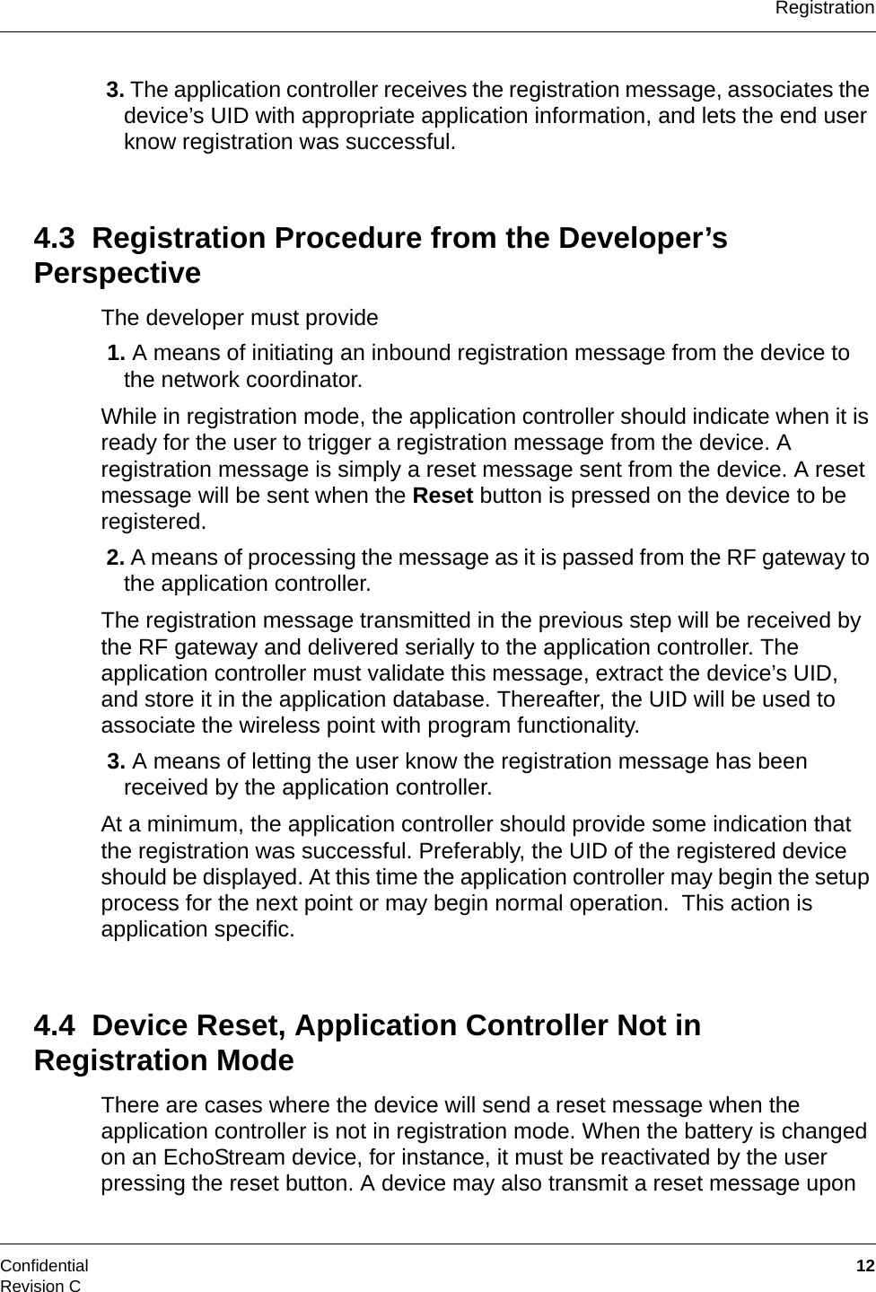
>
Inovonics Wireless
>
3B6OTPMTX User Manual
OEM instruction manual
Navigation menu
Upload a User Manual
Namespaces
Wiki Guide
HTML
PDF
Info
Views
User Manual
Discussion / Help
Navigation

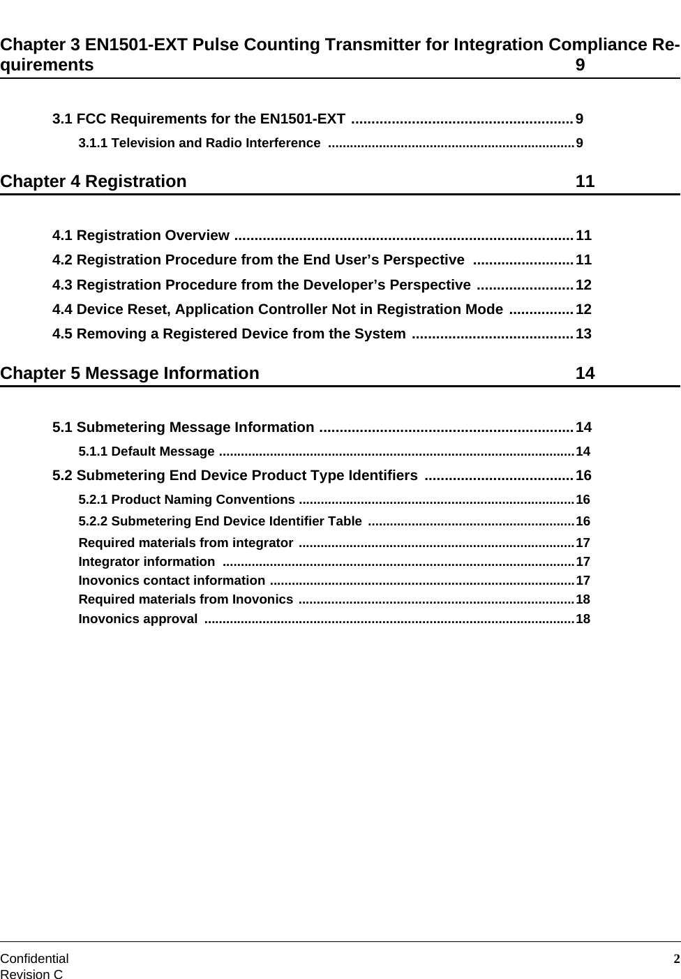
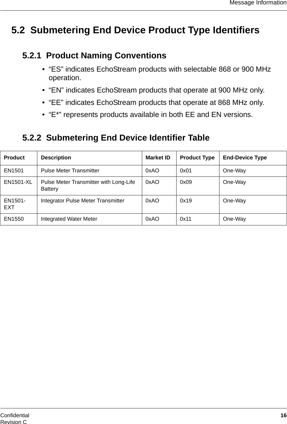
![Confidential 14Revision CChapter 5 Message Information5.1 Submetering Message InformationSubmetering end devices transmit meter and status information after ten pulses are received or after approximately sixty minutes since the last transmission, whichever comes first. Messages from security end-devices to the gateway adhere to the format defined following.Note: The format of EchoStream messages will vary depending on the message type. Always check the message class byte before attempting to determine the contents of a message.5.1.1 Default MessageNote: A number in parentheses following a data signifier represents the number of bytes the item contains. For example, unique ID (4) is a 4-byte field.[0x72] – Header for inbound complete message.[LEN] – Message length, excluding checksum.[UID (4) originator] – Unique ID of device originating message.[UID (4) first hop] – Unique ID of the device which received original message, as well as the signal level and margin. If the UID begins with 00, then the RF gateway is the first hop; if the UID begins with 01, then the repeater is the first hop.[Trace count (1)] - Number of trace unique IDs that follow. The default is zero, indicating no trace data.](https://usermanual.wiki/Inovonics-Wireless/3B6OTPMTX/User-Guide-1437898-Page-17.png)
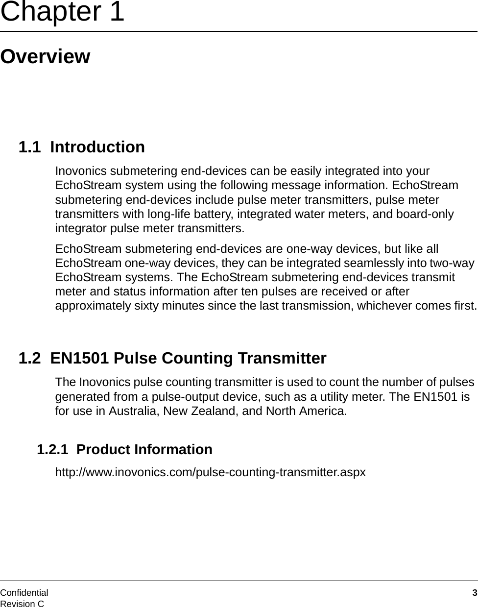
![Message InformationConfidential 15Revision CFUTURE: [Trace UID1 (4)]...[Trace UIDn (4)] - Unique ID of each device that repeats this message.[Hop count (1)] – The number of times this message was relayed by a device. [0x3E] - Message class byte for submetering data.[PTI] - Product type identifier.Note: See “Submetering End Device Product Type Identifiers” on page 16 for product type identifier information.[STAT1] - Application flags.Bit 7 - Delta totalizer.Bit 6 - Rapid transmission mode.Bit 5 - Reserved.Bit 4 - Reserved.Bit 3 - Reserved.Bit 2 - Reserved.Bit 1 - Reserved.Bit 0 - Reserved.[STAT0] - Primary Status Flags.Bit 7 - Reserved.Bit 6 - Low battery.Bit 5 - Case tamper.Bit 4 - Set when there has been no change in status since the last transmission.Bit 3 - Reset.Bit 2 - Set when the transmitter is entering sleep mode.Bit 1 - Reserved.Bit 0 - Reserved.[Level] – Signal level of message as measured by the first hop device.[Margin] – Signal margin of message as measured by the first hop device. [CKSUM] – Checksum.](https://usermanual.wiki/Inovonics-Wireless/3B6OTPMTX/User-Guide-1437898-Page-18.png)