Inovonics Wireless 3B6PORUNV Door/Window Transmitter User Manual WMG200 manuel

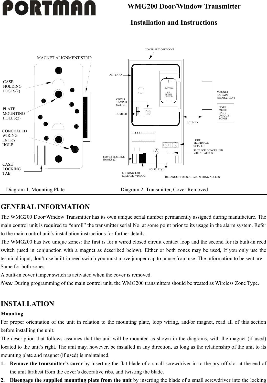
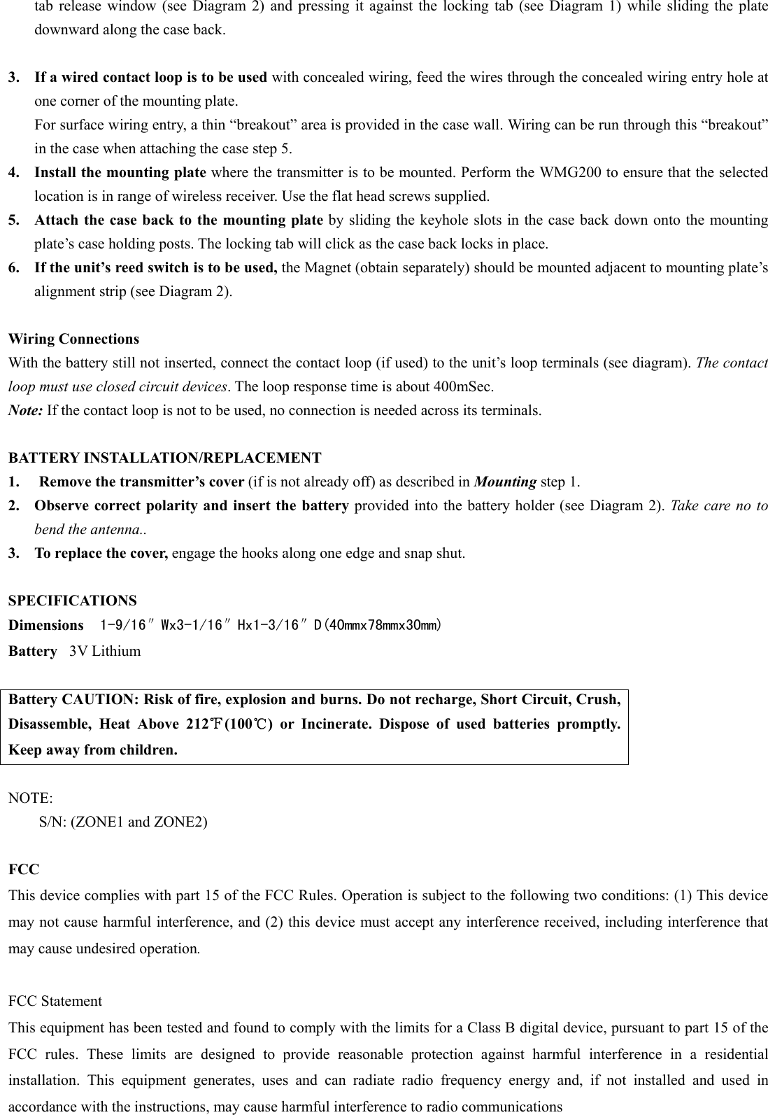
Inovonics Wireless Corporation Door/Window Transmitter WMG200 manuel

Manual

WMG200 Door/Window Transmitter        Installation and Instructions  CASEHOLDINGPOSTS(2)PLATEMOUNTINGHOLES(2)CONCEALEDWIRINGENTRYHOLECASELOCKINGTABMAGNET ALIGNMENT STRIP   BATTERY    REDSWITCH(INPUT 2)UNUSEUSEANTENNACOVERTAMPERSWITCHJUMPERCOVER HOLDING HOOKS (2)LOCKING TAB RELEASE WINDOWHOLE "A" (1)BREAKOUT FOR SURFACE WIRING ACCESSSLOT FOR CONCEALED WIRING ACCESSLOOP TERMINALS (INPUT1)NOTE:MG100HAS 2UNIQUEZONESMAGNET(OBTAINSEPARATELY)1/2'' MAXCOVER PRY-OFF POINTA                   Diagram 1. Mounting Plate                     Diagram 2. Transmitter, Cover Removed  GENERAL INFORMATION The WMG200 Door/Window Transmitter has its own unique serial number permanently assigned during manufacture. The main control unit is required to “enroll” the transmitter serial No. at some point prior to its usage in the alarm system. Refer to the main control unit’s installation instructions for further details. The WMG200 has two unique zones: the first is for a wired closed circuit contact loop and the second for its built-in reed switch (used in conjunction with a magnet as described below). Either or both zones may be used, If you only use the terminal input, don’t use built-in reed switch you must move jumper cap to unuse from use. The information to be sent are Same for both zones A built-in cover tamper switch is activated when the cover is removed. Note: During programming of the main control unit, the WMG200 transmitters should be treated as Wireless Zone Type.    INSTALLATION Mounting For proper orientation of the unit in relation to the mounting plate, loop wiring, and/or magnet, read all of this section before installing the unit. The description that follows assumes that the unit will be mounted as shown in the diagrams, with the magnet (if used) located to the unit’s right. The unit may, however, be installed in any direction, as long as the relationship of the unit to its mounting plate and magnet (if used) is maintained. 1. Remove the transmitter’s cover by inserting the flat blade of a small screwdriver in to the pry-off slot at the end of the unit farthest from the cover’s decorative ribs, and twisting the blade. 2. Disengage the supplied mounting plate from the unit by inserting the blade of a small screwdriver into the locking
tab release window (see Diagram 2) and pressing it against the locking tab (see Diagram 1) while sliding the plate downward along the case back.  3. If a wired contact loop is to be used with concealed wiring, feed the wires through the concealed wiring entry hole at one corner of the mounting plate. For surface wiring entry, a thin “breakout” area is provided in the case wall. Wiring can be run through this “breakout” in the case when attaching the case step 5. 4. Install the mounting plate where the transmitter is to be mounted. Perform the WMG200 to ensure that the selected location is in range of wireless receiver. Use the flat head screws supplied. 5. Attach the case back to the mounting plate by sliding the keyhole slots in the case back down onto the mounting plate’s case holding posts. The locking tab will click as the case back locks in place. 6. If the unit’s reed switch is to be used, the Magnet (obtain separately) should be mounted adjacent to mounting plate’s alignment strip (see Diagram 2).  Wiring Connections With the battery still not inserted, connect the contact loop (if used) to the unit’s loop terminals (see diagram). The contact loop must use closed circuit devices. The loop response time is about 400mSec. Note: If the contact loop is not to be used, no connection is needed across its terminals.  BATTERY INSTALLATION/REPLACEMENT     1.  Remove the transmitter’s cover (if is not already off) as described in Mounting step 1. 2. Observe correct polarity and insert the battery provided into the battery holder (see Diagram 2). Take care no to bend the antenna.. 3. To replace the cover, engage the hooks along one edge and snap shut.  SPECIFICATIONS Dimensions  1-9/16″Wx3-1/16″Hx1-3/16″D(40mmx78mmx30mm) Battery  3V Lithium  Battery CAUTION: Risk of fire, explosion and burns. Do not recharge, Short Circuit, Crush, Disassemble, Heat Above 212℉(100℃) or Incinerate. Dispose of used batteries promptly. Keep away from children.    NOTE: S/N: (ZONE1 and ZONE2)      FCC This device complies with part 15 of the FCC Rules. Operation is subject to the following two conditions: (1) This device may not cause harmful interference, and (2) this device must accept any interference received, including interference that may cause undesired operation.  FCC Statement This equipment has been tested and found to comply with the limits for a Class B digital device, pursuant to part 15 of the FCC rules. These limits are designed to provide reasonable protection against harmful interference in a residential installation. This equipment generates, uses and can radiate radio frequency energy and, if not installed and used in accordance with the instructions, may cause harmful interference to radio communications
 Any changes or modification not expressly approved by the party responsible could void the user's authority to operate the device.

Navigation menu